

Page 1

Providing Exceptional Consumer Optical Products Since 1975
Customer Support (800) 676-1343
E-mail: support@telescope.com
Corporate Offices (831) 763-7000
P.O. Box 1815, Santa Cruz, CA 95061
INSTRUCTION MANUAL
Orion
®
Tabletop Equatorial Mount
#9009
Page 2
2
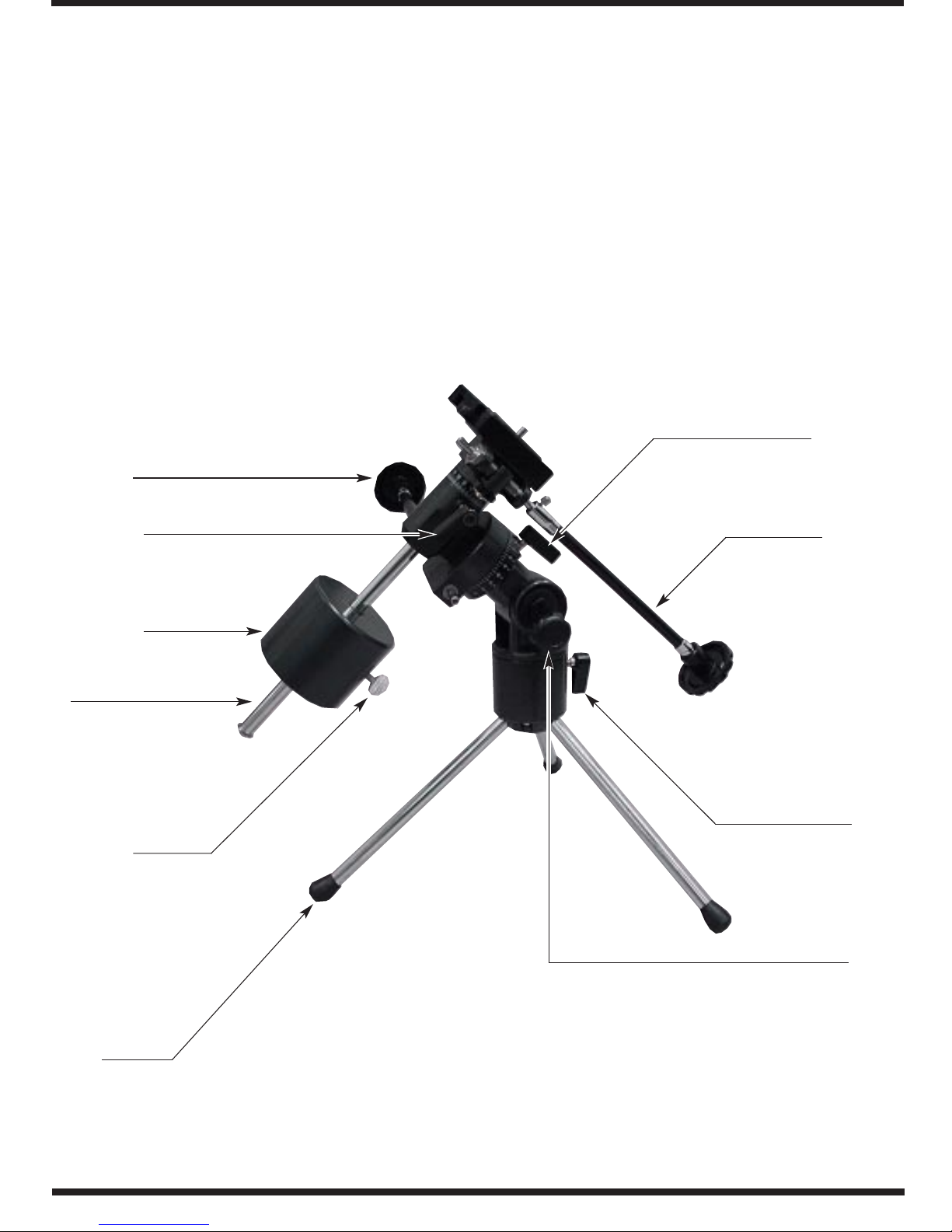
Figure 1. The Tabletop Equatorial Mount
Counterweight
Counterweight
shaft
R.A. slow-motion
control cable
Counterweight lock
thumb screw
Tr ipod leg
Latitude
lock knob
Azimuth
lock lever
Dec. slow-motion
control cable
R.A. lock lever
Dec. lock lever
Page 3
3
1. Parts List
Qty. Description
1 German-type equatorial mount
2 Slow-motion control cables
1 Counterweight
1 Counterweight shaft
3 Tripod legs
2. Assembly
Carefully remove all of the items from the shipping box.
Make sure all the parts listed in Section 1 are present.
Save the boxes and packaging material. In the unlikely
event that you need to return the mount, you must use
the original packaging.
Assembling the mount for the first time should take
about 5 minutes. No tools are needed. Refer to Figure
1 during the assembly process.
1.La y the equatorial mount on its side.Attach the tripod
legs, one at a time, by threading them into the holes
at the base of the mount.
2. With the tr ipod legs now attached to the equatorial
mount, stand the mount upright.
3. Orient the mount as it appears in Figure 2, at a latitude of about 40°, i.e., so that the pointer next to the
latitude scale is pointing to the hash mark at “40.”
To do this, loosen the latitude lock knob (below the lati-
tude scale), and adjust the latitude of the mount until the
pointer and the “40” line up.Then re-tighten the latitude
lock knob.You may also need to rotate the mount about
its right ascension (R.A.) and declination (Dec.) axes.
Do this by first loosening the R.A.and Dec.lock levers.
4.Slide the counterweight onto the counterweight shaft.
Make sure the counterweight lock thumb screw is
adequately loosened so the counterweight shaft can
pass through the hole in the counterweight. Position
the counterweight about halfway up the shaft and
tighten the counterweight lock thumb screw. The
washer and screw on the end of the counterweight
C
ongratulations on your purchase of a quality Orion product.
Your new Tabletop Equatorial Mount
is extremely portable and can be conveniently taken with you wherever you go to observe. A quickrelease mounting system allows fast and easy attachment of a wide variety of different telescope optical
tubes. With its precision yet highly portable equatorial head, you’ll be able to easily track astronomical
objects over time so that they remain within your eyepiece’s field of view. The setting circles will help
locate hundreds of fascinating celestial denizens, including galaxies, nebulas, and star clusters.With a
little practice and a little patience, you’ll find that your Tabletop Equatorial Mount is an invaluable tool for
getting the most out of your astronomical observing sessions.
These instructions will help you set up and properly use your equatorial mount. Please read them over
thoroughly before getting started.
Table of Contents
1. Parts List ................................................................................................................................ 3
2. Assembly ............................................................................................................................... 3
3. Attaching A Telescope ........................................................................................................... 4
4. Balancing the Telescope........................................................................................................ 5
5. Adjusting Height .................................................................................................................... 5
6. Aligning and Using the Equator ial Mount.............................................................................. 5
7. Specifications....................................................................................................................... 10
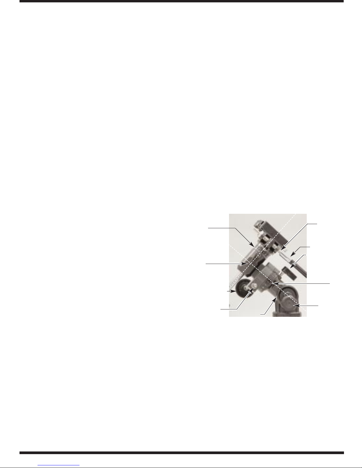
R.A. axis
Dec. axis
Dec. lock
lever
Dec. setting
circle
R.A. slowmotion
control cable
R.A. worm
gear shaft
R.A. setting
circle
Dec. worm
gear shaft
Dec.
slow-motion
control cable
R.A. lock lever
Latitude
lock knob
Latitude
scale
Figure 2: Close up of the equatorial mount
Page 4
4
shaft will prevent the counterweight from slipping off
the shaft and possibly onto your foot if the counterweight lock thumb screw should come loose.
5. Thread the counterweight shaft with counterweight
attached into the equatorial mount at the base of the
declination axis. Before a telescope is attached to the
mount, make sure the counterweight is oriented directly over a tripod leg, as shown in Figure 1. Otherwise,
the mount will tip over.To orient the counterweight relative to the tripod legs, loosen the azimuth lock lever
and rotate the mount left-to-right on the tripod. When
properly oriented, retighten the azimuth lock lever.
6. Now attach the two slow-motion control cables to the
R.A. and Dec. worm gear shafts (see Figure 2) of the
equatorial mount by positioning the thumb screw on the
end of the cable over the indented slot on the shaft, then
tightening the thumb screw .For the Dec.axis, attach the
cable to the longer end of the Dec. worm gear shaft. A
cable can be attached to either end of the R.A. worm
gear shaft, whichever is most convenient for you.
3. Attaching a Telescope
The Tabletop Equatorial Mount is designed to hold
small to mid-size telescopes weighing up to about 7
lbs. For heavier telescopes, the mount may not provide
sufficient stability for steady imaging. Many types of
telescopes can be mounted on the Tabletop Equatorial
Mount, including refractors and catadioptrics, provided
the telescope has a 1/4"-20 mounting block. 35mm
cameras can also be attached to the mount.
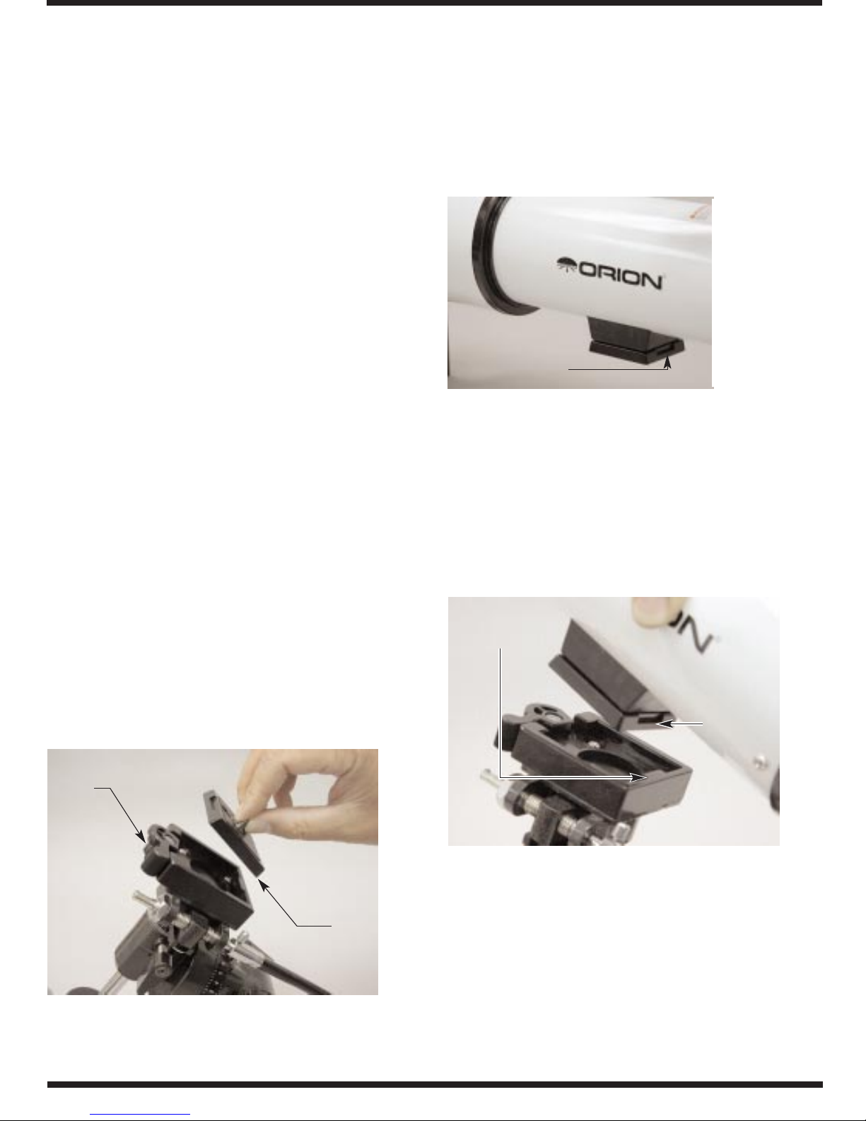
To connect your telescope to the Tabletop Equatorial
Mount, you must remove the mount's quick-release
mounting plate. Disengage the quick-release lever,
and pull the plate off the top of the mount. Grip the
plate by its threaded stud to do this (see Figure 3).
Now, attach the plate to your telescope by threading
the stud into the telescope's 1/4"-20 mounting block.
You can use a flat-head screwdriver in the slotted
screw head on the underside of the mounting plate to
firmly secure the plate to the telescope. Orient the
plate so the telescope is perpendicular to the slots on
the edge of the mounting plate (see Figure 4).
Replace the mounting plate, with telescope
attached, to the top of the equatorial mount. Register
the slots in the edges of the plate with the mating
feature on the mount's top (see Figure 5). Once the
plate is seated in its proper position, re-engage the
quick-release lever.
For transporting and storing your telescope, it is an easy
matter to remove the telescope from the mount. Simply
disengage the quick-release lever, and pull the telescope (with mounting plate attached) from the mount.
quick-release
lever
quick-
release
mounting
plate
slot in edge of
mounting plate
Figure 3:To remove the quick-release mounting
plate, disengage the quick-release lever and
grip the threaded stud.
Figure 4: Or ient the mounting plate so thatthe edge
slots are perpendicular to the telescope tube.
Figure 5: The edge slots on the mounting plate
register with the mount's top.
edge slot
mating
feature on
mount’s top
Page 5

5
4. Balancing the Telescope
Once the telescope is attached to the equatorial
mount, the next step is to balance the telescope
about the mount's R.A. axis. Proper balance is
required to insure smooth movement of the telescope on the equatorial mount.
Keeping one hand on the telescope optical tube, loosen
the R.A. lock lever. Make sure the Dec. lock lever is
locked. The telescope should now be able to rotate
freely about the R.A. axis. Rotate it until the counterweight shaft is parallel to the ground (i.e., horizontal).
Now loosen the counterweight lock thumb screw and
slide the weight along the shaft until it exactly counterbalances the telescope (see Figure 6a). That’s the
point at which the shaft remains horizontal even when
you let go of the telescope with both hands (see Figure
6b). Retighten the counterweight lock thumb screw.
The telescope is now balanced on the R.A. axis.
It is not possible to adjust the telescope's balance
about the Dec. axis of the mount. Usually, the telescope will be balanced naturally about the Dec. axis
due to the manufacturer's placement of the 1/4"-20
mounting block at the balance point of the telescope.
Now that the telescope is properly balanced, when you
loosen the lock lever on one or both axes and manually point the telescope, it should move without
resistance and should not drift from where you point it.
5. Adjusting Height
The Tabletop Equatorial Mount requires a sturdy table or
platform for use.Find a platform that will place the telescope's eyepiece at a comfortable height for viewing.
Typically, an outdoor picnic table will provide adequate
height and stability. Other outdoor platforms, like a tree
stump or large rock, can also be employed.
If you wish, you can use the equatorial mount on a standard photo-style tripod (see Figure 7). Simply remove
the three supplied tripod legs from the mount, and
thread the photo tripod's 1/4"-20 mounting stud into the
threaded hole on the bottom of the equatorial mount
casting. Lock the photo tripod's pan-head into place,
and move the telescope about the R.A.and Dec.ax es of
the equatorial mount only.
6. Aligning and Using the
Equatorial Mount
When you look at the night sky, you no doubt have
noticed that the stars appear to move slowly from east
Figure 6a, 6b: Slide the counterweight along the
counterweight shaft until it balances the
telescope tube.
6a.
6b.
Figure 7: The Tabletop
Equatoral Mount used
in conjunction with a
photo-style tripod.
Page 6

6
to west over time. That apparent motion is caused by
the Earth's rotation (from west to east). An equatorial
mount is designed to compensate for that motion,
allowing you to easily “track” the movement of astronomical objects, thereby keeping them from drifting out
of the telescope's field of view while you're observing.
This is accomplished by slowly rotating the telescope
on its right ascension axis, using only the R.A. slowmotion cable.But first the R.A. axis of the mount must
be aligned with the Earth's rotational (polar) axis; this
is a process called polar alignment.
Polar Alignment
For Northern Hemisphere observers, approximate
polar alignment is achieved by pointing the mount's
R.A. axis at the North Star, or Polaris. It lies within 1° of
the north celestial pole (NCP), which is an extension of
the Earth's rotational axis out into space. Stars in the
Northern Hemisphere appear to revolv e around P olaris.
To find Polaris in the sky, look north and locate the pattern of the Big Dipper (Figure 8). The two stars at the
end of the “bowl”of the Big Dipper point right to Polaris.
For general visual observation, an approximate polar
alignment is sufficient:
1. Loosen the latitude lock knob.Tilt the mount until the
pointer on the latitude scale is set at the latitude of
your observing site. If you don't know your latitude,
consult a geographical atlas to find it. For example,
if your latitude is 35° Nor th, set the pointer to +35
(see Figure 9).Then retighten the latitude lock knob.
The latitude setting should not have to be adjusted
again unless you move to a different viewing location some distance away.
2. Loosen the Dec. lock lever and rotate the telescope
optical tube until it is parallel with the R.A. axis (see
Figure 10). The pointer on the Dec. setting circle
should read 90°. Retighten the Dec. lock lever.
The two stars at the end of the "bowl" of the Big Dipper point to Polaris.
Figure 8. Finding Polaris
Big Dipper
(in Ursa Major)
Little Dipper
(in Ursa Minor)
N.C.P.
Pointer Stars
Cassiopeia
Polaris
latitude
scale
latitude
lock
knob
indicator
arrow
Figure 9: Adjust the tilt of the mount until the arrow
indicates your latitude on the latitude scale.Each
mark on the scale represents 5° increments.
Page 7

7
3. Loosen the azimuth adjustment lever and rotate the
entire equatorial mount left-to-right so the telescope
tube (and R.A. axis) points roughly at Polaris.If you
cannot see Polaris directly from your observing site,
consult a compass and rotate the equatorial mount
so the telescope points North. Retighten the azimuth
adjustment lever.
The equatorial mount is now polar aligned for casual
observing. From this point on in your observing session,
you should not make any further adjustments to the
azimuth or the latitude of the mount, nor should you mov e
the tripod.Doing so will undo the polar alignment.The telescope should be moved only about its R.A.and Dec.axes.
Use of the R.A. and Dec. Slow-Motion
Control Cables
The R.A. and Dec. slow-motion control cables allow
fine adjustment of the telescope's position to center
objects within the field of view. Before you can use
the cables, you must manually “slew” the mount to
point the telescope in the vicinity of the desired target. Do this by loosening the R.A. and Dec. lock
levers and moving the telescope about the mount's
R.A. and Dec. axes. Once the telescope is pointed
somewhere close to the object to be viewed, retighten the mount's R.A. and Dec. lock levers.
The object should now be visible somewhere in the
telescope's (aligned) finder scope. If it isn't, use the
slow-motion controls to scan the surrounding area of
sky. If the object is still not visible in the finder scope,
you will need to slew the mount again, this time
being more careful to point the telescope closer to
what you wish to view.
When the object is visible in the finder scope, use
the slow-motion controls to center it.Now, look in the
telescope with a long focal length (low magnification)
eyepiece. If the finder scope is properly aligned, the
object should be visible somewhere in the field of
view. If it is not, you may need to realign the telescope's finder scope.
Once the object is visible in the telescope's eyepiece, use the slow-motion controls to center it in the
field of view.You can now switch to a higher magnification eyepiece, if you wish. After switching
eyepieces, you can use the slow-motion control
cables to re-center the image, if necessary.
The Dec. slow-motion control cable can move the
telescope a maximum of 25°. This is because the
Dec. slow-motion mechanism has a limited range of
mechanical travel. (The R.A. slow-motion mechanism has no limit to its amount of travel.) If you can
no longer rotate the Dec. control cable in a desired
direction, you have reached the end of travel, and
the slow-motion mechanism should be reset. This is
done by first rotating the control cable several turns
in the opposite direction from which it was originally
being turned. Then, manually slew the telescope
closer to the object you wish to observe (remember
to first loosen the Dec.lock lever).You should now be
able to use the Dec. slow-motion control cable again
to fine adjust the telescope's position.
Tracking Celestial Objects
When you observe a celestial object through the telescope, you'll see it drift slowly across the field of view.
To keep it in the field, if your equatorial mount is polaraligned, just rotate the R.A. slow-motion control. The
Dec. slow-motion control is not needed for tracking.
Objects will appear to move faster at higher magnifications, because the field of view is narrower.
Understanding the Setting Circles
The setting circles on an equatorial mount enable you
to locate celestial objects by their “celestial coordinates.” Every astronomical object resides in a specific
location on the “celestial sphere.”That location is denoted by two numbers: its right ascension (R.A.) and
declination (Dec.). In the same way, every location on
Earth can be described by its longitude and latitude.
R.A. is similar to longitude on Earth, and Dec. is similar
to latitude. The R.A. and Dec. values for celestial
objects can be found in any star atlas or star catalog.
So, the coordinates for the Orion Nebula listed in a star
atlas will look like this:
R.A. 5h 35.4m Dec. -5° 27'
R.A. axis
Figure 10:
Loosen the Dec.
lock lever and
rotate the
telescope tube
until it is
parallel with the
R.A. axis.
Page 8

8
That's 5 hours and 35.4 minutes in right ascension, and
-5 degrees and 27 arc-minutes in declination (the negative sign denotes south of the celestial equator). There
are 60 minutes in 1 hour of R.A and there are 60 arcminutes in 1 degree of declination.
The mount’s R.A. setting circle is scaled in hours, from 1
through 24, with small hash marks in between representing 20 minute increments.The Dec. setting circle is scaled
in degrees, with each small hash mark representing 2.5°.
Before you can use the setting circles to locate objects,
the mount must be well polar aligned, and the setting
circles must be calibrated.The declination setting circle
was calibrated at the factory, and should read 90° when
the telescope optical tube is parallel with the R.A. axis.
The R.A. setting circle needs to be calibrated before
each observing session.
Calibrating the Right Ascension
Setting Circle
1. Identify a bright star near the celestial equator and
look up its coordinates in a star atlas.
2. Loosen the R.A.and Dec.lock levers on the equatorial
mount, so the telescope optical tube can move freely.
3 Point the telescope at the bright star near the celes-
tial equator whose coordinates you know. Center the
star in the telescope's field of view. Lock the R.A.and
Dec. lock levers.
4. There are three indicator arrows for the R.A. setting
circle. Choose one that is most conveniently positioned for easy visual reference, and rotate the R.A.
setting circle so the arrow indicates the R.A. coordinate listed for the bright star in the star atlas (see
Figure 11). Refer only to the chosen indicator arrow
when subsequently using the R.A. setting circle to
find objects.
Finding Objects With the Setting Circles
Now that both setting circles are calibrated, look up in a
star atlas the coordinates of an object you wish to view.
1. Loosen the Dec. lock lever and rotate the telescope
until the value pointed to by the Dec. setting circle
indicator arrow matches the Dec.coordinate from the
star atlas. Retighten the lock lever.
Note: If the telescope is aimed south and the Dec.setting circle indicator arrow passes the 0° mark, the value on the Dec.
setting circle becomes a negative number.
2. Loosen the R.A.lock lever and rotate the telescope until
the value pointed to by the R.A. setting circle indicator
arrow matches the R.A.coordinate from the star atlas.
Most setting circles are not accurate enough to put an
object dead-center in your finder scope's field of view,
but they'll get you close, assuming the equatorial mount
is accurately polar aligned. The R.A. setting circle
should be re-calibrated ever y time you wish to locate a
new object.Do so by calibrating the setting circle for the
centered object before moving on to the next one.
Confused About Pointing Your Telescope?
Beginners occasionally experience some confusion
about how to point their telescope overhead or in other
directions. In Figure 10, the telescope is pointed north
as it would be during polar alignment. The counterweight shaft is oriented downward.But it will not look like
that when the telescope is pointed in other directions.
Let’s say you want to view an object that is directly overhead, at the zenith. How do you do it?
One thing you DO NOT do is mak e any adjustment to the
mount's latitude (tilt).That will nullify the polar alignment.
Remember, once the mount is polar aligned, the telescope should be moved only on the R.A.and Dec.axes.
To point the scope overhead, first loosen the R.A. lock
lever and rotate the telescope on the R.A. axis until the
counterweight shaft is horizontal (parallel to the ground).
Then loosen the Dec. lock lever and rotate the telescope
until it is pointing straight overhead (See Figure 12).The
counterweight shaft is still horizontal.Then retighten both
lock levers.
Figure 11: Rotate the R.A. setting circle until the
chosen indicator arrow points to the R.A. coordinate of
the alignment star.Only one of the three indicator
arrows is shown.
R.A.
setting
circle
indicator
arrow
Page 9

9
Similarly, to point the telescope directly south, the counterweight shaft should again be horizontal. Then you
simply rotate the scope on the Dec. axis until it points in
the south direction. (Figure 13a).
What if you need to aim the telescope directly north, but
at an object that is nearer to the horizon than Polaris?
You can’t do it with the counterweight down as pictured
in Figure 10.Again, you have to rotate the scope in R.A.
so that the counterweight shaft is positioned horizontally. Then rotate the scope in Dec. so it points to where
you want it near the horizon.(Figure 13b)
To point the telescope to the east (Figure 13c) or west
(Figure 13d), or in other directions, you rotate the telescope on its R.A. and Dec. axes. Depending on the
altitude of the object you want to observe, the counterweight shaft will be oriented somewhere between
vertical and horizontal.
The key things to remember when pointing the telescope
is that a) you only move it in R.A.and Dec., not in azimuth
or latitude (altitude), and b) the counterweight and shaft
will not always appear as it does in Figure 10. In fact it
almost never will!
Figure 12: The mount
is positioned as it
would be if attempting
to observe at
the zenith.
Figure 13a, 13b, 13c, 13d:
The Tabletop Equatorial
Mount with a telescope
pointing (a.) south, (b.) north,
(c.) east, and (d.) west.
13d.
13c.
13b.
13a.
Page 10

7. Specifications
Mount: German-type equatorial
Tripod: aluminum
Height: 13"
Weight: 9.8 lbs
Counterweight: 5.0 lbs
Maximum Loading Weight: about 7 lbs
Slow-Motion Adjustment: both RA and Dec axes
Setting Circles: RA scaled in 20 min. increments, Dec
scaled in 2.5° increments
Polar Axis Altitude Adjustment:15° to 90°
10
Page 11

11
One-Year Limited Warranty
This Orion Tabletop Equatorial Mount is warranted against defects in materials or workmanship
for a period of one year from the date of purchase.This warranty is for the benefit of the original retail purchaser only. During this warranty period Orion Telescopes & Binoculars will repair
or replace, at Orion’s option, any warranted instrument that proves to be defective, provided it
is returned postage paid to: Orion Warranty Repair, 89 Hangar Way, Watsonville, CA 95076. If
the product is not registered, proof of purchase (such as a copy of the original invoice) is
required.
This warranty does not apply if, in Orion’s judgment, the instrument has been abused, mishandled, or modified, nor does it apply to normal wear and tear.This warranty gives you specific
legal rights, and you may also ha ve other rights, which vary from state to state.F or further warranty service information, contact: Customer Service Department, Orion Telescopes &
Binoculars, P. O.Box 1815, Santa Cruz, CA 95061; (800) 676-1343.
Orion Telescopes & Binoculars
Post Office Box 1815, Santa Cruz, CA 95061
Customer Support Help Line (800) 676-1343 • Day or Evening
 Loading...