

Page 1
INSTRUCTION MANUAL
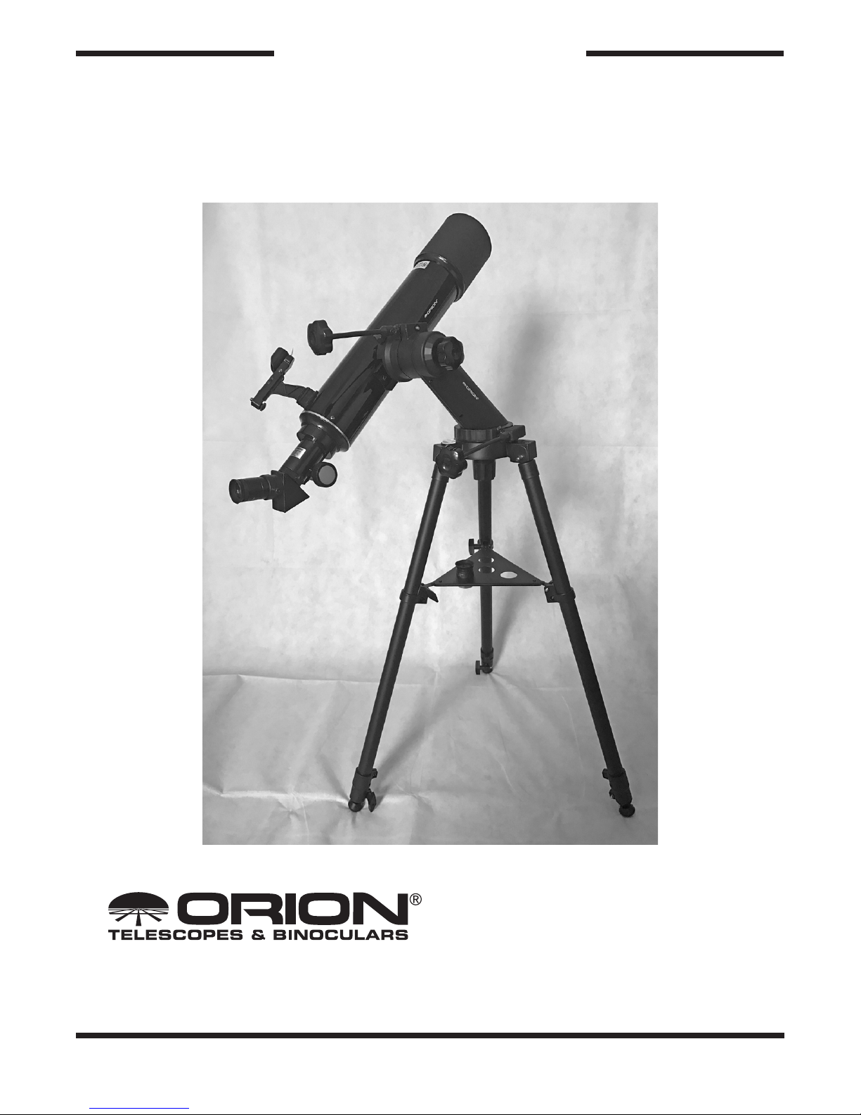
Orion® VersaGo E-Series 90mm
Altazimuth Refractor
#52590
Providing Exceptional Consumer Optical Products Since 1975
All Rights Reserved. No part of this product instruction or any of its contents may be reproduced, copied, modified or adapted,
without the prior written consent of Orion Telescopes & Binoculars.
Customer Support:
www.OrionTelescopes.com/contactus
Corporate Offices:
89 Hangar Way, Watsonville CA 95076 - USA
Copyright © 2018 Orion Telescopes & Binoculars
IN 615 Rev. A 04/18
Page 2
Congratulations on your purchase of a quality Orion product. The VersaGo E-Series 90mm
Altazimuth Refractor is a versatile and easy-to-use telescope designed for exploring scenic daytime
vistas as well as scanning the night skies for celestial treasures.
These instructions will help you set-up, properly use and care for your instrument. Please read them
over carefully before getting started.
A
E
C
J
G HI
F
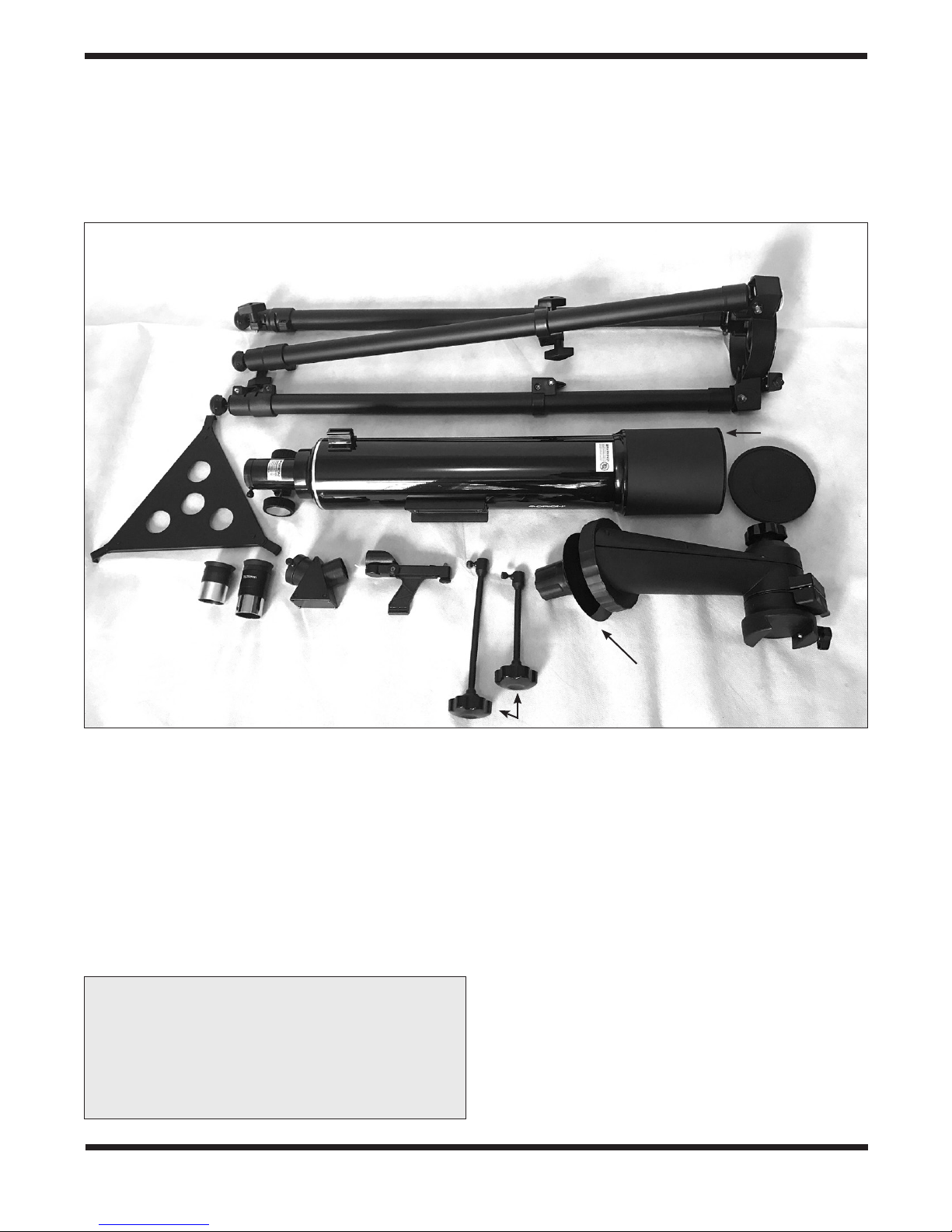
Figure 1. Included parts of the VersaGo E-Series Mount
Included Parts
Unpack all of the parts and lay them out in your workspace.
Make sure all the parts listed below and shown in Figure 1 are
present. Save the shipping box and packaging material. In the
unlikely event that you need to return the mount, you must use
the original packaging. Initial assembly of the mount is easy and
should take only about 15 minutes.
WARNING: NEVER look directly at the Sun
through your telescope—even for an instant—
without a professionally made solar filter that
completely covers the front of the instrument,
or permanent eye damage could result. Young
children should use this telescope only with
adult supervision.
B
Plastic disk
D
Parts List
A Tripod
B Altazimuth arm
C Accessory tray and leg brace
D Micro-motion cables
(short and long)
E Optical tube
F 25mm Plossl eyepiece, 1.25"
G 10mm Plossl eyepiece, 1.25"
H Red dot finder scope
I 45-degree correct-image diagonal
J Dust cap
K MoonMap 260 (not shown in Fig. 1)
2
Page 3
1. Assembly
1. Stand the tripod (A) upright and spread the legs apart a
little. Keep the tripod legs at their shortest (fully retracted)
length for now; you can extend them to a more desirable
length later, after the mount is fully assembled.
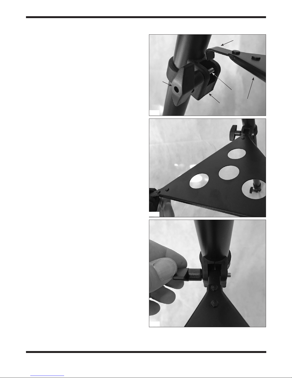
2. To attach the accessory tray (C), place a hooked tab on one
of the three corners of the tray over the screw in the leg collar, as shown in Figure 2A. Connect the tray to the other two
legs in the same manner (2B), then tighten all three of the
tray lock knobs (2C) to secure the tray in place.
3. Now you’ll install the altazimuth arm (B) onto the tripod.
Remove the azimuth tension knob and washer from the center shaft on the bottom of the arm. Then place the base of the
arm on the tripod’s mounting platform, inserting the center
shaft into the hole in the tripod’s mounting platform. (NOTE:
The large plastic disk, which is identified in Figure 1,
goes between the mounting arm and the tripod’s mounting platform.) Then replace the washer and azimuth tension
knob to secure the arm in place (Figure 3).
4. Attach the two micro-motion cables (D). The shorter of the two
is usually preferred for the altitude axis and the longer one
for the azimuth axis. Loosen the thumbscrew at the end of
the cable, then line up the cable end so that the thumbscrew
is over the flat side of the axle on each axis (Figure 4). Press
the cable end over the axle, then tighten the thumbscrew to
secure the cable in place. The thumbscrew should protrude
down into the dimple in the axle, to insure that the cable will
not slip off the axle. Once attached the micro-motion cables
should appear as in Figure 5.
Lock
knob
2A
Screw
Leg
collar
Hooked tab
Accessory tray
Attaching the Telescope Optical Tube
to the Mount
The E-Series Altazimuth Mount features a dovetail mounting
saddle that accommodates Vixen-style mounting bars (Figure
6A). Slide the dovetail bar attached to the side of the optical
tube into the saddle, then secure it in place by tightening the
saddle lock knob (Figure 6B). (You may have to loosen the
saddle lock knob a little before attempting to slide in the dovetail
bar, to allow clearance for the bar.)
Installing the Accessories
With the tube now securely attached to the mounting arm,
install the red dot finder scope (H) on the optical tube. Do this
by orienting the finder scope as shown in Figure 7 and slide the
bracket foot back into the finder scope base as far as it will go.
Now insert the correct-image diagonal (I) into the focuser drawtube and tighten the thumbscrew on the drawtube collar. Then
insert the 25mm eyepiece (F) into the diagonal and secure it by
lightly tightening the thumbscrew on the diagonal (Figure 8).
The telescope is now completely assembled and should appear
as in Figure 9! Before it can be effectively used, however, there
are a couple of things to do to prepare the telescope for operation.
2B
2C
Figure 2. A) Hook the tray corner over the screw in the leg
collar, B) Repeat for the other two legs, then C) Tighten all
three tray lock knobs
3
Page 4
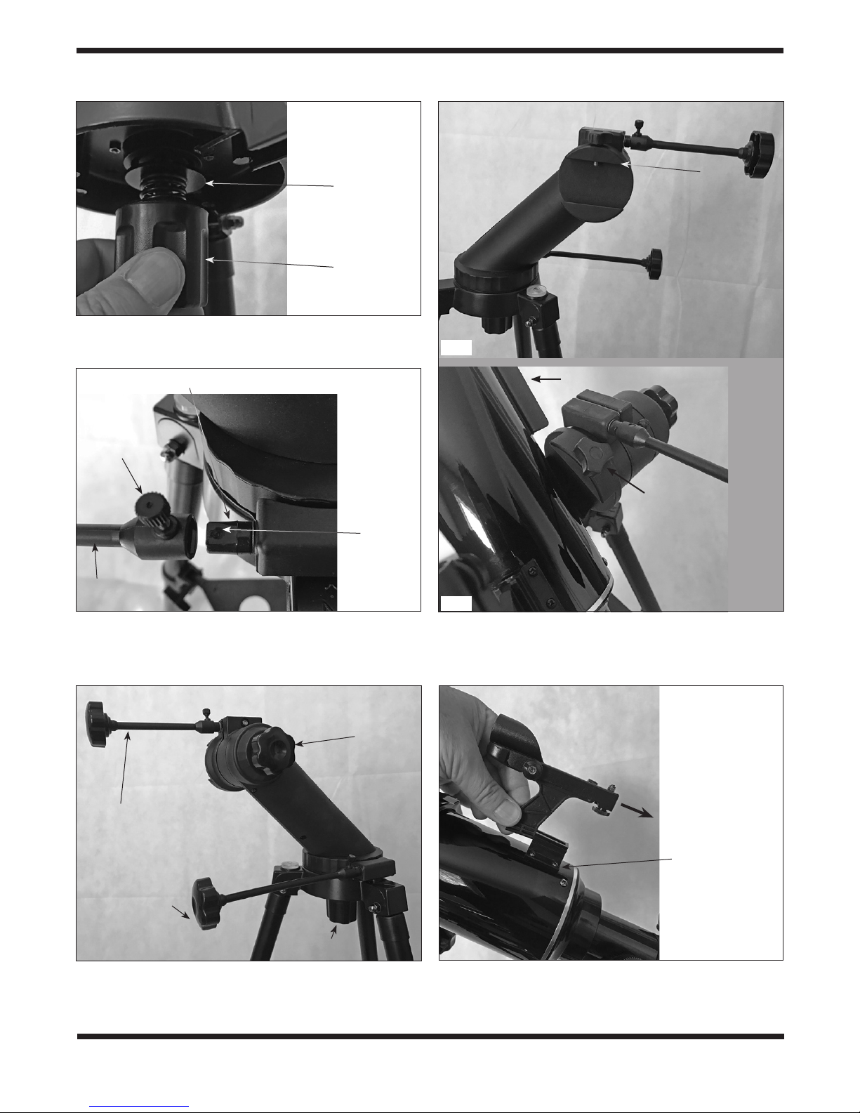
Washer
Azimuth
tension knob
Figure 3. Secure the altazimuth arm to the tripod with the
washer and azimuth tension knob.
Saddle
6A
Axle
Thumbscrew
Dimple
Micro-motion
cable
Figure 4. When attaching the micro-motion cables, make
sure the thumbscrew is directly over the dimple on the flat
side of the axle.
Altitude tension
knob
Dovetail bar
Lock knob
6B
Figure 6. A) The dovetail saddle B) Slide the dovetail bar
on the optical tube into the saddle of the mounting arm,
then tighten the lock knob to secure the instrument onto
the mount.
Altitude micromotion cable
Azimuth micromotion cable
Azimuth
tension knob
Figure 5. The mount has two large tension knobs and
two micro-motion cables to allow precise movement of
your instrument.
4
Finder scope
base
Figure 7. Slide the red dot finder scope’s bracket into its base.
Page 5

Power switch
Tab
Battery compartment
8 9
Figure 8. Install the diagonal
and an eyepiece in the
focuser as shown.
Figure 9. The fully assembled
VersaGo E-Series 90mm
Altazimuth Refractor
Preparing the Telescope
for Operation
Aligning and Using the Red Dot Finder Scope
The included red dot finder scope (H) makes pointing your telescope almost as easy as pointing your finger! It’s a non-magnifying aiming device that superimposes a tiny LED-illuminated
red dot on the sky, showing exactly where the telescope is
pointed. It permits easy object targeting prior to observation in
the higher-power main telescope.
Before you can use the red dot finder scope, you must remove
the tab sticking out from the battery compartment (Figure 10).
Doing so will allow the pre-installed 3V CR-2032 button cell bat-
tery to make contact with the finder scope’s electronic circuitry
to power the finder’s red LED illuminator. The tab can then be
discarded.
To use the red dot finder scope properly, it must be aligned with
the main telescope. This is easiest to do during daylight hours,
before observing at night. Follow this procedure:
1. First, remove the dust cap (J) from the front of the telescope.
2. With the star diagonal and 25mm eyepiece already in place,
point the telescope at a well-defined land target (e.g., the
top of a telephone pole) that’s at least a quarter mile away.
Center the target in the eyepiece by moving the optical
tube by hand, with the altitude and azimuth tension knobs
slightly loosened to allow easy movement in both axes),
then by turning the slow-motion cables as needed to center
the target object.
Vertical
adjustment
knob
Horizontal
adjustment
knob
Figure 10. The red dot finder scope has vertical and (inset)
horizontal adjustment knobs for aligning it with the telescope.
object should appear in the field of view somewhere near
the red dot.
NOTE: This finder has two brightness settings. When the
switch is set all the way over to the ON position, the red dot
is brightest. But in between the OFF and ON positions is a
middle setting in which the red dot is dim. Typically the dim
setting is used under dark skies and the brighter setting is
used under light-polluted skies or in daylight.
4. You’ll want to center the target object on the red dot. To do
so, without moving the telescope, use the finder scope’s
vertical and horizontal adjustment knobs (shown in Figure
10) to position the red dot on the object.
5. When the red dot is centered on the distant object, check
to make sure the object is still centered in the telescope’s
eyepiece. If it isn’t, re-center it then adjust the finder
scope’s alignment again. When the object is centered in
the telescope eyepiece and on the finder scope’s red dot,
the finder scope is properly aligned with the telescope. The
red dot finder scope’s alignment should be checked before
every observing session.
At the end of your observing session, be sure to slide the power
switch on the red dot finder scope to OFF to preserve battery
life.
Opposite side
2. Using the VersaGo
3. Now that a distant target is centered in the main telescope’s
eyepiece, turn on the red dot finder scope by sliding the
power switch to ON (refer to Figure 10). Position your
eye at a comfortable distance from the rear of the unit.
Look through the round window of the finder scope with
both eyes open to see the illuminated red dot. The target
E-Series Mount
The VersaGo E-Series mount allows motion in two axes: altitude
(up and down) and azimuth (left and right). Hence, the VersaGo
E-Series is an “altazimuth” mount. To make coarse movements
of your instrument, loosen the azimuth tension knob and/or the
altitude tension knob (see Figure 5) to slew the instrument to
your target. Then lightly retighten the knob(s). When set to the
5
Page 6

proper tension – not too tight and not too loose — you should
be able to move the instrument without having to adjust the tension knobs each time. The friction will be sufficient to allow the
instrument to move but also to stay put when you let go of it
to observe. To make finer directional adjustments to the instrument, turn the hand knobs on the micro-motion cables.
The azimuth axis is rotatable 360 degrees and the altitude axis
has 180 degrees of motion.
Tripod Height Adjustment
There is a leg extension segment on each tripod leg to allow
quick height adjustment. Simply loosen the winged leg lock
knobs half a turn or so, extend the leg to the desired length,
then retighten the winged knobs.
Tripod Feet
Note that at the bottom of each tripod leg is a rubber foot. If
desired, the foot can be retracted by rotating it clockwise to
expose a metal spike, when needed for extra grip on slippery
surfaces. If the spikes are not needed, rotate the rubber foot
counterclockwise until the spike is recessed in the foot and no
longer protruding.
Accessory Tray
The triangular accessory tray acts as a tripod leg brace as well
as a storage rack for 1.25" telescope eyepieces or accessories.
The four holes in the tray accommodate the barrels of 1.25"
accessories.
3. Astronomical Observing
For many, this will be your first foray into the exciting world of
amateur astronomy. The following information and observing
tips will help get you started.
Choosing an Observing Site
When selecting a location for observing, get as far away as
possible from direct artificial light such as street lights, porch
lights, and automobile headlights. The glare from these lights
will greatly impair your dark-adapted night vision. Set up on
a grass or dirt surface, not asphalt, because asphalt radiates
more heat. Heat disturbs the surrounding air and degrades the
images seen through the telescope. Avoid viewing over rooftops and chimneys, as they often have warm air currents rising
from them. Similarly, avoid observing from indoors through an
open (or closed) window, because the temperature difference
between the indoor and outdoor air will cause image blurring
and distortion.
If at all possible, escape the light-polluted city sky and head for
darker country skies. You’ll be amazed at how many more stars
and deep-sky objects are visible in a dark sky!
“Seeing” and Transparency
Atmospheric conditions vary significantly from night to night.
“Seeing” refers to the steadiness of the Earth’s atmosphere at
a given time. In conditions of poor seeing, atmospheric turbulence causes objects viewed through the telescope to “boil.” If
you look up at the sky and stars are twinkling noticeably, the
seeing is poor and you will be limited to viewing at lower magni-
fications. At higher magnifications, images will not focus clearly.
Fine details on the planets and Moon will likely not be visible.
In conditions of good seeing, star twinkling is minimal and images appear steady in the eyepiece. Seeing is best overhead,
worst at the horizon. Also, seeing generally gets better after
midnight, when much of the heat absorbed by the Earth during
the day has radiated off into space.
Especially important for observing faint objects is good “transparency”—air free of moisture, smoke, and dust. All tend to scat-
ter light, which reduces an object’s brightness. Transparency is
judged by the magnitude of the faintest stars you can see with
the unaided eye (5th or 6th magnitude is desirable).
Cooling the Telescope
All optical instruments need time to reach “thermal equilibrium.” The bigger the instrument and the larger the temperature
change, the more time is needed. Allow at least 30 minutes for
your telescope to acclimate to the temperature outdoors before
you start observing with it.
Let Your Eyes Dark-Adapt
Don’t expect to go from a lighted house into the darkness of the
outdoors at night and immediately see faint nebulas, galaxies,
and star clusters—or even very many stars, for that matter. Your
eyes take about 30 minutes to reach perhaps 80% of their full
dark-adapted sensitivity. As your eyes become dark-adapted,
more stars will glimmer into view and you’ll be able to see fainter details in objects you view in your telescope.
To see what you’re doing in the darkness, use a red-filtered
flashlight rather than a white light. Red light does not spoil your
eyes’ dark adaptation like white light does. A flashlight with a red
LED light is ideal. Beware, too, that nearby porch, streetlights,
and car headlights will ruin your night vision.
Eyepiece Selection
Magnification, or power, is determined by the focal length of
the telescope and the focal length of the eyepiece being used.
Therefore, by using eyepieces of different focal lengths, the
resultant magnification can be varied. It is quite common for
an observer to own five or more eyepieces to access a wide
range of magnifications. This allows the observer to choose
the best eyepiece to use depending on the object being viewed
and viewing conditions. Your VersaGo E-Series 90mm refractor
comes with 25mm and 10mm eyepieces, which will suffice nicely to begin with. You can purchase additional eyepieces later if
you wish to have more magnification options.
Magnification is calculated as follows:
600 mm
25 mm
For example, the VersaGo E-Series 90mm has a focal
length of 600mm, which when used with the supplied 25mm
eyepiece yields:
= 24x
6
Page 7

600 mm
10 mm
= 60x
The magnification provided by the 10mm eyepiece is:
Telescope Focal Length (mm)
Eyepiece Focal Length (mm)
= Magnification
The maximum attainable magnification for a telescope is directly related to how much light it can gather. The larger the aperture, the more magnification is possible. In general, a figure of
50x per inch of aperture is the maximum attainable for most
telescopes. Going beyond that will yield simply blurry, unsatisfactory views. Your VersaGo E-Series 90mm refractor has an
aperture of 90mm, or 3.5 inches, so the maximum magnification would be about 175x (3.5 x 50). This level of magnification
assumes you have ideal atmospheric conditions for observing
(which is seldom the case).
Keep in mind that as you increase magnification, the bright-
ness of the object viewed will decrease; this is an inherent
principle of the laws of physics and cannot be avoided. If magnification is doubled, an image appears four times dimmer. If
magnification is tripled, image brightness is reduced by a factor
of nine!
So start by using the 25mm eyepiece, then try switching to the
10mm eyepiece later if you want to boost the magnification.
Focusing the Telescope
To focus the telescope, turn the focus wheels (Figure 8) forward or back until you see your target object (e.g., stars, the
Moon, etc.) in the eyepiece. Then make finer adjustments
until the image is sharp. If you’re having trouble achieving initial focus, rack the focuser drawtube all the way in using the
focus wheels, then while looking into the eyepiece slowly turn
the focus wheels so that the drawtube extends outward. Keep
going until you see your target object come into focus. Note that
when you change eyepieces you may have to adjust the focus a
bit to get a sharp image with the newly inserted eyepiece.
What to Expect
So what will you see with your telescope? The VersaGo
E-Series 90mm Altazimuth Refractor provides great views both
in daytime and at night. The 45-degree correct-image diagonal provides a normal, right-side-up image, which is important
for daytime terrestrial viewing. For nighttime viewing of celestial objects, while there is no “right side up” in space, the normal, upright orientation will make moving the telescope to, say,
center an object in the eyepiece very intuitive. However, if you
would prefer a 90-degree “star” diagonal for a more comfortable
viewing position when observing objects overhead, one can be
purchased separately. Note, though, that a standard star diagonal will render a mirror reversed image in the eyepiece, rather
than a correctly oriented image. So we do not recommend a
star diagonal for terrestrial viewing.
For celestial viewing, you should be able to see bands on
Jupiter, the rings of Saturn, craters on the Moon, the waxing
and waning of Venus, and many bright deep-sky objects such
as star clusters and nebulas. Do not expect to see colors in faint
objects as you do in photographs, however. Most galaxies and
nebulas will appear gray in color. Unlike a camera, which can
record colors of faint objects in long exposures, our eyes are
not sensitive enough to see such color except in a few of the
brightest ones.
Celestial Objects to Observe
A. The Moon
With its rocky surface, the Moon is one of the easiest and most
interesting objects to view with your telescope. Lunar craters,
maria, and even mountain ranges can all be clearly seen from a
distance of 238,000 miles away! With its ever-changing phases,
you’ll get a new view of the Moon every night. The best time
to observe our one and only natural satellite is during a partial
phase, that is, when the Moon is not full. During partial phases,
shadows are cast on the surface, which reveal more detail,
especially right along the border between the dark and light
portions of the disk (called the “terminator”). A full Moon is too
bright and devoid of surface shadows to yield a pleasing view.
Make sure to observe the Moon when it is well above the horizon to get the sharpest images.
Use an optional Moon filter to dim the Moon when it is very
bright. It simply threads onto the bottom of the eyepieces (you
must first remove the eyepiece from the focuser to attach a fil-
ter). You’ll find that the Moon filter improves viewing comfort,
and helps to bring out subtle features on the lunar surface.
B. The Planets
The planets don’t stay put like the stars, so to find them you
should refer to the monthly star charts at OrionTelescopes.com,
or to charts published monthly in Astronomy, Sky & Telescope,
or other astronomy magazines. Venus, Mars, Jupiter, and
Saturn are the brightest objects in the sky after the Sun and the
Moon. Other planets may be visible but will likely appear star-
like. Because planets are quite small in apparent size, optional
higher-power eyepieces or a Barlow lens are recommended
and often needed for detailed observations.
B. The Sun
You can change your nighttime telescope into a daytime Sun
viewer by installing an optional full-aperture solar filter over the
front opening of the telescope. The primary attraction is sunspots, which change shape, appearance, and location daily.
Sunspots are directly related to magnetic activity in the Sun.
Many observers like to make drawings of sunspots to monitor
how the Sun is changing from day to day.
IMPORTANT NOTE: Do not look at the sun with any optical
instrument without a professionally made solar filter,
or permanent eye damage could result.
D. The Stars
Stars will appear like twinkling points of light. Even powerful
telescopes cannot magnify stars to appear as more than a point
of light. You can, however, enjoy the different colors of the stars
and locate many pretty double and multiple stars. The famous
7
Page 8

“Double-Double” in the constellation Lyra and the gorgeous twocolor double star Albireo in Cygnus are favorites. Defocusing a
star slightly can help bring out its color.
E. Deep-Sky Objects
Under dark skies, you can observe a wealth of fascinating deepsky objects, including gaseous nebulas, open and globular star
clusters, and different types of galaxies. Most deep-sky objects
are very faint, so it is important you find an observing site well
away from light pollution.
To find deep-sky objects with your telescope, you first need
to become reasonably familiar with the night sky. Unless you
know how to recognize the constellation Orion, for instance, you
won’t have much luck locating the Orion Nebula. A simple planisphere, or star wheel, can be a valuable tool for learning the
constellations and seeing which ones are visible in the sky on
a given night. Once you have identified a few constellations, a
good star chart, atlas, or astronomy app will come in handy for
helping locate interesting deep-sky objects to view within the
constellations.
Do not expect these objects to appear like the photographs you
see in books and on the internet; most will look like dim gray
smudges. Our eyes are not sensitive enough to see color in
deep-sky objects except in a few of the brightest ones. But as
you become more experienced and your observing skills get
sharper, you will be able to ferret out more and more sub¬tle
details and structure.
4. Telescope Care and
Maintenance
If you give your telescope reasonable care, it will last a lifetime.
Store it in a clean, dry, dust-free place, safe from rapid changes
in temperature and humidity. Do not store the telescope outdoors, although storage in a garage or shed is okay. Small components like eyepieces and other accessories should be kept
in a protective box or storage case. Keep the dust cover on the
front of the telescope when it is not in use.
Your refractor telescope requires very little mechanical maintenance. The optical tube has a smooth painted finish that is
fairly scratch-resistant. If a scratch does appear on the tube, it
will not harm the telescope. If you wish, you may apply some
auto touch-up paint to the scratch. Smudges on the tube can be
wiped off with a soft cloth and household cleaning fluid.
time, using a fresh lens tissue on each area. Never reuse tissues.
When bringing the telescope inside after an evening’s viewing
it is normal for moisture to accumulate on the lenses due to
the change in temperature. We suggest leaving the telescope
and eyepieces uncovered overnight to allow the condensation
to evaporate.
5. Specifications
Objective lens: 90mm (3.5") diameter, achromatic
Effective focal length: 600mm
Focal ratio: f/6.7
Lens coatings: Fully antireflection coated
Focuser: Rack-and-pinion, accepts 1.25"
accessories
Eyepieces: 25mm and 10mm Plossls,1.25"
barrel diameter, threaded for
Orion filters
Eyepiece coatings: Fully antireflection coated
Diagonal: 45-degree correct-image, 1.25"
Eyepiece magnification: 24x (with 25mm eyepiece) and
60x (with 10mm eyepiece)
Finder scope: Red dot finder scope, two
brightness levels
Mount: Single-arm altazimuth
Azimuth range: 360 degrees
Altitude range: 180 degrees
Tripod: Aluminum
Mount height, legs extended: 57-1/4"
Mount height, legs retracted: 36"
Total instrument weight: 11lbs. 10.8 oz
Cleaning Optics
Any quality optical lens cleaning tissue and optical lens cleaning
fluid specifically designed for multi-coated optics can be used
to clean the lenses of your telescope and eyepieces. Never
use regular glass cleaner or cleaning fluid designed for eyeglasses. Before cleaning, remove any loose particles or dust
from the lens with a blower bulb or soft brush. Then apply some
cleaning fluid to a tissue, never directly on the optics. Wipe the
lens gently in a circular motion, then remove any excess fluid
with a fresh lens tissue. Oily fingerprints and smudges may be
removed using this method. Use caution; rubbing too hard may
scratch the lens. On larger lenses, clean only a small area at a
8
Page 9

This page left blank intentionally.
9
Page 10

10
This page left blank intentionally.
Page 11

This page left blank intentionally.
11
Page 12

One-Year Limited Warranty
This Orion product is warranted against defects in materials or workmanship for a period of one year
from the date of purchase. This warranty is for the benefit of the original retail purchaser only. During
this warranty period Orion Telescopes & Binoculars will repair or replace, at Orion’s option, any warranted instrument that proves to be defective, provided it is returned postage paid. Proof of purchase
(such as a copy of the original receipt) is required. This warranty is only valid in the country of purchase.
This warranty does not apply if, in Orion’s judgment, the instrument has been abused, mishandled, or
modified, nor does it apply to normal wear and tear. This warranty gives you specific legal rights. It is
not intended to remove or restrict your other legal rights under applicable local consumer law; your state
or national statutory consumer rights governing the sale of consumer goods remain fully applicable.
For further warranty information, please visit www.OrionTelescopes.com/warranty.
Orion® Telescopes & Binoculars
Corporate Offices: 89 Hangar Way, Watsonville CA 95076 - USA
Customer Support: www.OrionTelescopes.com/contactus
Copyright © 2018 Orion Telescopes & Binoculars
All Rights Reserved. No part of this product instruction or any of its contents may be reproduced, copied, modified or adapted, without the prior
written consent of Orion Telescopes & Binoculars.
12
 Loading...