


Speedtrac Getting Started
Version:6.07.01
By Hyper Terminal
Date:2008/1/23
© 2007 ORION Technology LTD. All rights reserved. 1/33

Table of Contents
1. Introduction ............................................................................................................3
I. Package contents:........................................................................................3
II. M12-V Cable pin assignment:..................................................................... 3
III. Speedtrac LED indicators:........................................................................ 4
IV. Speedtrac mode-selection switch:.......................................................... 5
2. Configuration by Hyper Terminal..........................................................................6
I. Hardware and Software preparation.......................................................... 6
II. Basic Configuration.......................................................................................8
III. GPRS Connection Configuration..........................................................10
IV. Gateway Server Configuration..............................................................13
V. Function Variables Configuration – Mileage Report..............................14
VI. Function Variables Configuration – ParkFence Setting ....................16
VII. Function Variables Configuration – GeoFence Setting.....................18
3. Running on Normal Mode....................................................................................22
4. Test protocol commands via RS-232 connection.................................................30
5. Get system logs via RS-232 connection for advanced debugging....................... 32
© 2007 ORION Technology LTD. All rights reserved. 2/33
1. Introduction
I. Package contents:
1. Speedtrac x 1
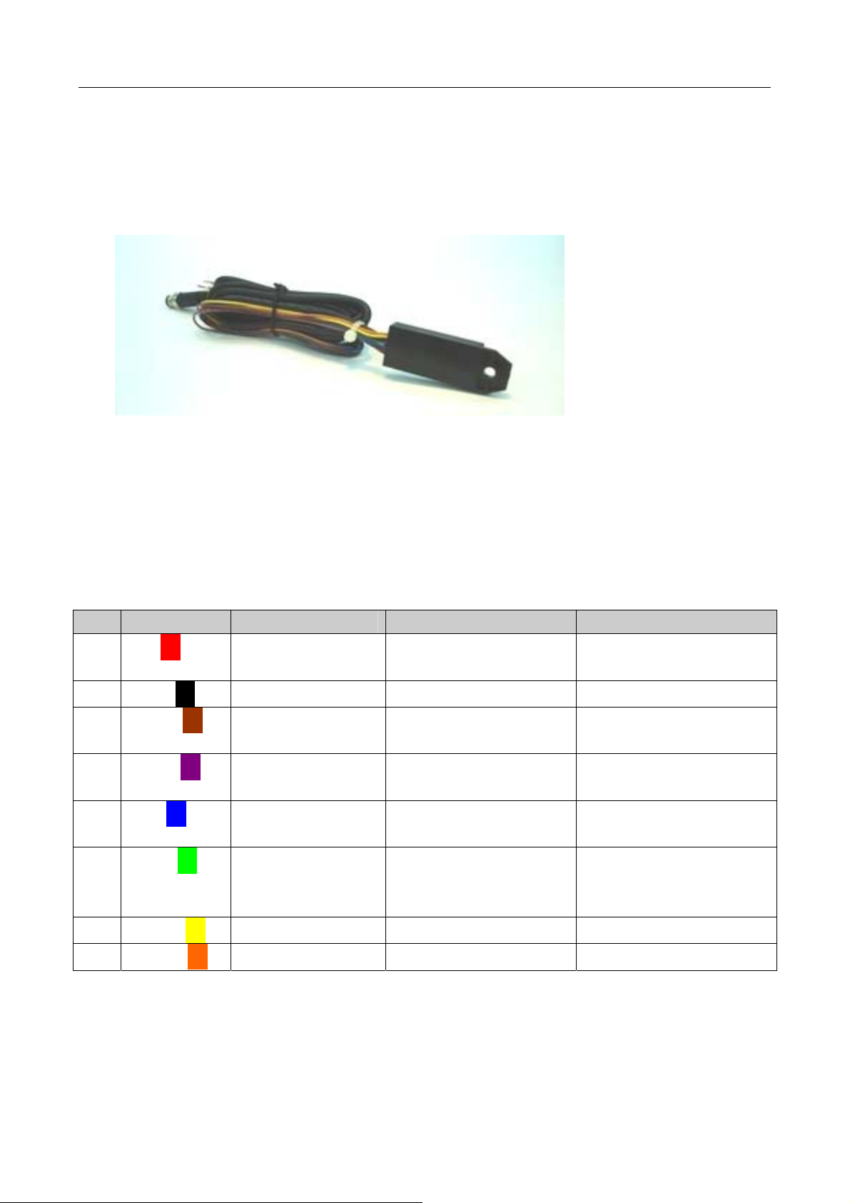
2. M12-V cable x 1 (with waterproof connector, 8-pin cable and surge
protector) – For vehicle installation
3. M12-R cable x 1 (with waterproof connector, RS-232 connecor) – For
configuration
4. AC adapter x 1 (Only available in the testing sample package)
5. Vehicle power adapter x 1 (Only available in the testing sample
package)
II. M12-V Cable pin assignment:
PIN Color Name Description Range
1
2
3
4
5
6
7
Red□
Black□
Brown□
Purple□
Blue□
Green□
Yellow□
PWR Power supply input DC, 12V~24V +- 5%
Imax <= 2A
GND Ground 0V
Digital Input 1 Reserved for Ignition
Input (ACC Input)
Digital Output 1 General purpose
Digital Output
Digital Output 2 General purpose
digital Output
Digital Input 2 General purpose
digital input (Positive
High : 12V~24V
Low : 0V
500 mA max @
12V~24V
500 mA max @
12V~24V
High : 12V~24V
Low : 0V
trigger)
NC Reserved
8
Orange□
NC Reserved
© 2007 ORION Technology LTD. All rights reserved. 3/33

III. Speedtrac LED indicators:
PWR
GSM
GPS
ON: System Error
OFF: System Error
Flash: System running( 1sec ON 1sec OFF)
OFF: GSM module OFF or Error, No SIM Card, Searching
networks)
Flash: GSM registered (0.5sec ON 0.5sec OFF)
Flash: GPRS connecting (0.25sec ON 0.25sec OFF)
ON: Socket session online (connect to tcpserver running on
the Gateway Server which is the Primary Server of a tracker)
OFF: GPS module OFF or Error
Flash: Searching GPS signal
ON: GPS fixed
FCC warning statement
This model complies with part 15/22H/24E of the FCC Rules. Operation is subject to
the condition that this device does not cause harmful interference. This device complies
with Part 15 of the FCC Rules. Operation is subject to the following two conditions: (1)
this device may not cause harmful interference and (2) this device must accept any
interference received, including interference that may cause undesired operation.
© 2007 ORION Technology LTD. All rights reserved. 4/33
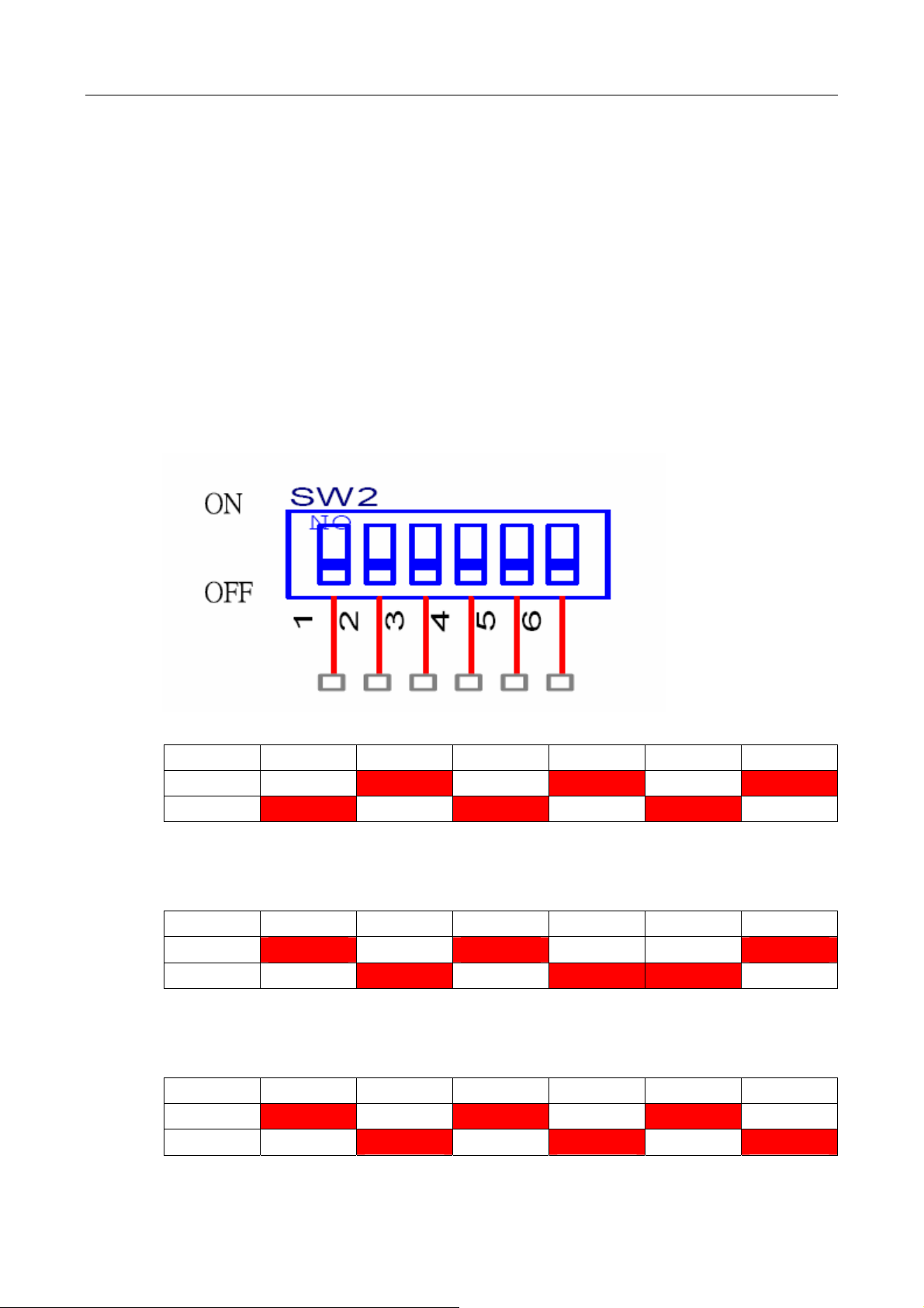
Speedtrac mode-selection switch:
1. There is a switch when opening the battery cover of Speedtrac. It is
designed to select different modes of Speedtrac. There are 3 modes
of Speedtrac.
A. Installation mode: Use M12-V cable to install Speedtrac in the
vehicle. 2 Digital Inputs (Including 1 x ignition input) and 2 Digita l
outputs are available in Installation mode.
B. Debug mode: Use M12-R cable to connect to PC COM port for
configuration.
C. Download mode: Use M12-R cable to connect to PC COM port
to download the new firmware of Speedtrac.
2. The three-mode selections are listed below:
A. Installation mode (with 2xDI and 2xDO):
1 2 3 4 5 6
ON V V V
OFF V V V
B. Debug mode (Configuration):
1 2 3 4 5 6
ON V V V
OFF V V V
C. Download mode (Update firmware):
1 2 3 4 5 6
ON V V V
OFF V V V
© 2007 ORION Technology LTD. All rights reserved. 5/33
2. Configuration by Hyper Terminal
I. Hardware and Software preparation
1. Remove the battery cover of Speedtrac and insert a SIM card with
GPRS service enabled. Lock the SIM card.
2. Adjust the mode-selection switch to ‘Debug mode’ (1-3-6 ON, 2-4-5
OFF).
3. Use a M12-R cable (with a RS-232 connector) to connect Speedtrac
to a PC COM port.
4. Open Hyper Terminal (or other terminal program) at Windows Start
Menu:
All Programs\Accessories\Communications\Hyper Terminal.
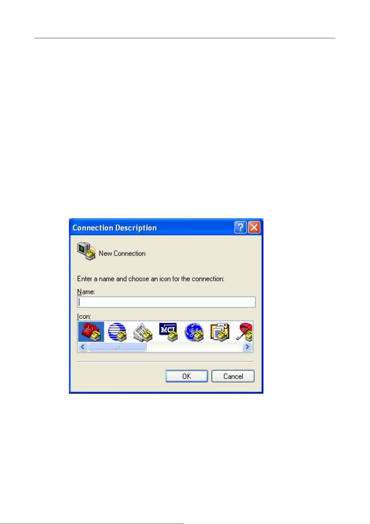
5. Add a new connection, enter Name as ‘Speedtrac’. Click “OK” and
select the COM Port for the Speedtrac connection.
© 2007 ORION Technology LTD. All rights reserved. 6/33
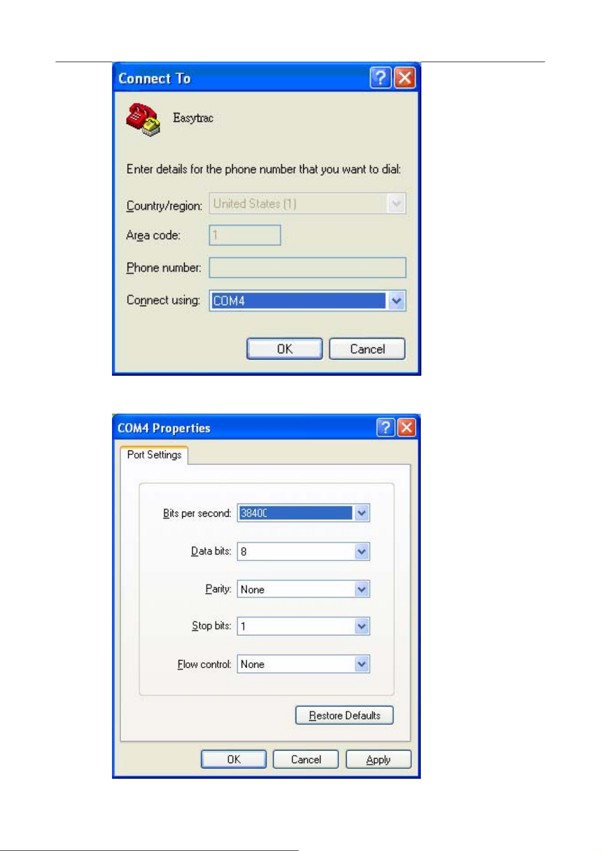
6. Set the Baud rate as 38,400 bps and Flow control as none. Press “OK”.
© 2007 ORION Technology LTD. All rights reserved. 7/33

7. Connect the M12-R cable power-plug to the AC adapter and press
the ‘ESC’ key of the PC keyboard within 3 second after the tracker is
POWER ON until the text messages show on the Hyper Terminal
screen. In doing so, Speedtrac boots on ‘Debug Mode’ (Configuration
Mode).
8. Normally, the first LED is flashing constantly which means the
Speedtrac is POWER ON and running. It shows the following
messages on the Hyper Terminal.
Speedtrac Version : EZ960903
- Build Date : Spe 03 2007
- Build Time : 18:11:39
- Serial Number : EZ2000000139
- Unit ID : 2000000139
- IMEI : 352021002964245
Type "H" for the Debug Mode Commands Menu.
$> <Press Enter>
Invalid Command
$>H
9. If you don’t see the above messages on the Hyper Terminal or if there
is no response when you press ‘Enter’ of the Keyboard, please check
the settings of Hyper Terminal and reconnect the power adapter.
Otherwise, please send an email to
support@oriontech.com.tw for
technical support.
II. Basic Configuration
1. Type ‘H’ to show the Co
UPPER CASE.
Use ‘HW’ comma
2. nd to show the hardware information.
$>H
Speedtrac Debug Mode Command Menu:
CVCFG - Clear Variable Configuration.
DCFG - Restore Firmware Default Configuration.
HW - Show Hardware Information.
LOG - Display all Logs.
LOG_RESET - Reset all Logs.
mmand Menu. All commands should be
© 2007 ORION Technology LTD. All rights reserved. 8/33

FLASH_RESET - Reset Whole FLASH Chip to 0x00.
SCFG - Set Configuration.
T - Test Mode.
$...& - Protocol Commands Test.
$> HW <Press Enter>
Hardware Information
1. ModelName : Speedtrac SP3510
2. Speedtrac Hardware Version: V6
3. Manufacturing Date : 20070705
4. Manufacturing Place : Taiwan
5. Manufacturing Firmware Version : 0705MP
6. Speedtrac Serial Number : EZ2000000139
7. Speedtrac UnitID : 2000000139
8. Speedtrac GSM/GPRS Module Info : SIEMEMS MC55 04.00
9. Speedtrac GPS Module Info : RoyalTek REB-3310 1.3.5.56
0. Speedtrac Configuration Mode : FLASH
$>
3
. Use ‘SCFG’ command to enter ‘Main Setting Menu’. Then type ‘1’ to
enter ‘Basic Setting Menu’. For initialization or regular application, no
basic setting needs to be changed.
$>SCFG <Press Enter>
Main Setting Menu :
1. Basic Setting
2. GSM/GPRS Connection Setting
3. Gateway Server Setting
4. Function Variables Setting
E. Exit
Selection [1-3]? 1 <Press Enter>
Basic Setting Menu :
0. Configuration Version : 0A0
1. Speedtrac Firmware : 0705MP
2. Speedtrac UnitID : 2000000139 : [0000000000-4294967296]
3. Speedtrac User Password : 0000
4. Speedtrac Enable COM1 for DEBUG : YES : [NO|YES]
5. Speedtrac COM1 Baudrate: 38400 : [38400|19200|9600|4800]
E. Exit
Selection [1-9]?
Basic Setting Menu :
© 2007 ORION Technology LTD. All rights reserved. 9/33

Field Mandatory Description
UnitID
Password
Enable
DEBUG
COM1
Baud rate
4. When you finish the ‘Basic Settings’ to return to ‘Main Setting
5
5
5
5
Device Unit ID. Default value is the same as the serial
number.
Range from ‘0000000000’ to ‘4294967296’. Other
characters are not allowed. Maximum: 10 digits
Default value : ”0000”.
Range from “0000” to “9999”.
YES: Debug messages output to COM1
NO: No debug messages output to COM1
Default value: “38400”
[38400|19200|9600|4800]
, type ‘E’
Menu’.
III. GPRS Connection Configuration
1. Type ‘2’ to enter ‘GSM/GPRS Connec
initialization or regular application, no setting of this menu nee
changed.
Main Setting Menu :
1. Basic Setting
2. GSM/GPRS Connection Setting
3. Gateway Server Setting
4. Function Variables Setting
E. Exit
Selection [1-3]? 2 <Press Enter>
GSM/GPRS Connection Setting Menu :
1. Speedtrac Switch Mode : GPRS : [AUTO|GPRS|SMS]
2. Speedtrac GPRS Reconnect : 8 : [8-65535]
3. Speedtrac SMS Duration : 180 : [180-65535]
4. SIM PIN1&2 Setting
SIM PIN1 :
SIM PIN2 :
5. GPRS Connection Setting
6. SMS Connection Setting
E. Exit
tion Setting Menu’. For
ds to be
© 2007 ORION Technology LTD. All rights reserved. 10/33

Selection [1-6]?
GSM/GPRS Connection Setting Menu :
Field Mandatory Description
Switch
Mode
GPRS
Reconnect
SMS
Duration
5
5
AUTO: The tracker sends reports by GPRS as first
priority. When the GPRS service is not available, the
tracker sends reports by SMS instead.
GPRS: The tracker sends reports by GPRS only.
SMS: The tracker sends reports by SMS only.
Default value : ”8”. Unit = ‘time’
Range from “8” to “65535”.
When Switch Mode=AUTO: The tracker will try to open
GPRS connection M times. After retry M times, the tracker
will send reports by SMS.
When Switch Mode=GPRS: The tracker will try to open
GPRS connection M times. After retry M times, the tracker
will reboot itself and do it over.
Default value : ”180”. Unit = ‘second’
Range from “180” to “65535”.
When Switch Mode=AUTO: The tracker will try to open
GPRS connection M times. After retry M times, the tracker
will send reports by SMS for N seconds. After N seconds,
the tracker will try to open GPRS connection again.
SIM PIN1
SIM PIN2
PIN1 of the SIM card to be used in the tracker
Default Value = “”.
PIN2 of the SIM card to be used in the tracker
Default Value = “”.
. Type ‘5’ to enter ‘GPRS Connection Setting Menu’. The GPRS
2
connection parameters are provided by the Telecom operator.
Note: All GPRS connection parameters have to be correct, othe
the tracker can not open GPRS connection successfully.
rwise
© 2007 ORION Technology LTD. All rights reserved. 11/33

Selection [1-6]? 5 <Press Enter>
GPRS Connection Setting Menu :
1. GPRS Dial Number :
2. GPRS User Name :
3. GPRS Password :
4. GPRS APN : internet
5. GPRS Enable : START : [STOP|START|ACCON]
6. GPRS Report Interval : 30 : [15-65535]
7. GPRS SYNC Interval : 300 : [15-65535]
8. GPRS Filter : NO : [YES|NO]
9. GPRS DNS : 0.0.0.0
E. Exit
Selection [1-9]?
GPRS Connection Setting Menu :
Field Mandatory Description
Dial Number
User Name
Password
APN
Enable
5
5
GPRS dialup phone number.
GPRS Login User Name
GPRS Login Password
Access Point Name
STOP : Stop the GPRS tracking action. The tracker
sends SYNC packet by SYNC interval to the Gateway
server to keep alive.
START : The tracker sends GPS data over GPRS as
long as it is powered ON. No matter the ACC (Ignition)
is ON or OFF.
ACCON : The tracker sends GPS data over GPRS only
when the ACC is ON. When the ACC is OFF, the
tracker sends SYNC packet by SYNC interval to the
Gateway server to keep alive.
Report
Interval
SYNC
Interval
5
5
GPS data Report Interval. The unit is ‘second’.
Default Value = “30”.
Range from “15” to 65535”.
SYNC packet Interval: The unit is ‘second’
Range from “150” to “65535”.
© 2007 ORION Technology LTD. All rights reserved. 12/33

Default = 300 Seconds. Set longer Sync Interval to
save GPRS cost.
Filter
DNS
5
YES : Filter the invalid GPS data. Only send the valid
GPS data
NO : Not Filter GPS data. Send all GPS data, no matter
the GPS data is valid or invalid.
DNS Server IP address
3. When you finish the ‘GPRS Connection Settings’, type ‘E’ to return to
‘G /GPRS Con tion type ‘E’ to return to
SM nec Setting Menu’. Then
‘Main Setting Menu’.
IV. Gateway Server Configuration
. Type ‘3’ to enter ‘Gateway Server Setting Menu’. Note: The Gateway
1
Server settings have to be correct,
GPRS connection and build a socket session with the Gateway
otherwise the tracker can not open
Server correctly.
Main Setting Menu :
1. Basic Setting
2. GSM/GPRS Connection Setting
ting 3. Gateway Server Set
4. Function Variables Setting
E. Exit
Selection [1-3]? 3 <Press Enter>
Gateway Server Setting Menu :
1. Server Resync Setting
Server Resync Enable : YES : [NO|YES]
Server Resync Time (min): 60 : [0-65535]
2. Primary Gateway Server
Server IP : 220.128.135.215
Server Port : 9998 : [0-65535]
E. Exit
Selection [1-2]?
© 2007 ORION Technology LTD. All rights reserved. 13/33

ateway Server Setting Menu : G
Field Mandatory Description
Resync
Enable
Resync
Time
Server IP
Server Port
5
5
5
5
YES: the tracker will send a SYNC packet to the Gateway
Server and request an ACK to verify the communication
between the tracker and the Gateway Server is OK. If the
tracker can not get the correct ACK from the Gateway
Server, it will store the GPS data in the Flash Memory and
try to reconnect to the Gateway Server.
Note: Some internet disconnection problem can not be
detected by the GSM module, the Resync mechanism
can prevent long time disconnect problem.
Time interval of the tracker to send SYNC packet to the
Gateway Server and request an ACK.
Primary Gateway Server IP address or Domain Name, if
using Domain Name. DNS Server IP address of GPRS
connection settings is needed.
The port number of the Primary Gateway Server to
receive GPS data
2. When you finish the ‘Ga to
teway Server Settings’, type ‘E’ to return
‘Main Setting Menu’.. All Gateway Server Settings have to be correct,
otherwise the tracker can not connect to the Gateway Server
successfully.
V. Fun bles Configuration – Mileage Report
ction Varia
. Type ‘4’ to enter ‘Function Variables Setting Menu’. Then type ‘1’ to
1
enter ‘Mileage Report Setting Menu’. The settings are to act
‘Track by Distance’ function.
Main Setting Menu :
1. Basic Setting
2. GSM/GPRS Connection Setting
3. Gateway Server Setting
etting 4. Function Variables S
E. Exit
Selection [1-3]? 4 <Press Enter>
ivate the
© 2007 ORION Technology LTD. All rights reserved. 14/33

Function Variables Setting Menu :
1. Mileage Report Setting Menu
2. ParkFence Setting Menu
3. GeoFence Setting Menu
E. Exit
Selection ? 1 <Press Enter>
Mileage Report Setting Menu :
1. Total Mileage : 0.000000
2. Mileage Limitation : 0.000000
3. Distance Interval Track : 0.000000
E. Exit
Selection ?
Mileage Report Setting Menu :
Field Mandatory Description
Total
Mileage
Mileage
Limitation
Distance
Interval
Track
The accumulated mileages of the tracker.
A mileage limitation to send a ‘logOverMile’ Event Report
when Total Mileage reaches this limitation. Then it will be
reset to 0.
A distance interval to send a ‘logDistance’ event report.
The unit is ‘mile’.
2. When you finish the ‘Mileage Report Settings’, type ‘E’ to return to
‘Main Setting Menu’. Then type ‘YES’ to apply all settings to the Flash
Memory.
Main Setting Menu :
1. Basic Setting
2. GSM/GPRS Connection Setting
3. Gateway Server Setting
etting 4. Function Variables S
E. Exit
Selection [1-3]? E <Press Enter>
© 2007 ORION Technology LTD. All rights reserved. 15/33

Write to the External FLASH [YES|NO]? YES <Press Enter>
FLASH Sector Erase Start
Sector Number : 0x01 - Sector Address : 0x00010000
FLASH Sector Erase Done
Writing 0x0000053C Bytes
FLASH Reset Done
Done.
FLASH Sector Erase Start
Sector Number : 0x01 - Sector Address : 0x00020000
FLASH Sector Erase Done
Writing 0x0000069C Bytes
FLASH Reset Done
Done.
$>
VI. Function Variables Configuration – ParkFence Setting
. Use ‘SCFG’ command to enter ‘Main Setting Menu’. Then type ‘4’ to
1
enter ‘Function Variables Setting Menu’. Then type ‘2’ to enter
‘ParkFence Setting Menu’. The settings are to activate the
‘ParkFence’ function.
Main Setting Menu :
1. Basic Setting
2. GSM/GPRS Connection Setting
3. Gateway Server Setting
etting 4. Function Variables S
E. Exit
Selection [1-3]? 4 <Press Enter>
Function Variables Setting Menu :
1. Mileage Report Setting Menu
2. ParkFence Setting Menu
3. GeoFence Setting Menu
E. Exit
Selection ? 2 <Press Enter>
© 2007 ORION Technology LTD. All rights reserved. 16/33

ParkFence Setting Menu:
1. ParkFence Enable : NO
2. ParkFence Radius (mile) : 0.0000
3. Alarm Time Interval : 0
4. Moved Distance : 0.0000
5. Current ParkFence Status : 0
E. Exit
Selection ?
ParkFence Setting Menu :
Field Mandatory Description
ParkFence
Enable
ParkFence
Radius
Alarm Time
Interval
Moved
Distance
ParkFence
Status
5
5
YES : Enable ParkFence feature when the driver parks
the vehicle.
NO : Disable ParkFence feature.
A Radius distance of the ParkFence to trigger a
‘logGeoOut’ event report. The unit is ‘mile’.
A Time Interval to continuous trigger a ‘logGeoOut’ event
report when the vehicle keeps staying outside of the
ParkFence.
Reserved. For debugging only.
Reserved. For debugging only.
1. When you finish the ‘Pa ’ to return to ‘Main
rkFence Settings’, type ‘E
Setting Menu’. Then type ‘YES’ to apply all settings to the Flash
Memory.
Main Setting Menu :
1. Basic Setting
2. GSM/GPRS Connection Setting
3. Gateway Server Setting
etting 4. Function Variables S
E. Exit
Selection [1-3]? E <Press Enter>
Write to the External FLASH [YES|NO]? YES <Press Enter>
FLASH Sector Erase Start
© 2007 ORION Technology LTD. All rights reserved. 17/33

Sector Number : 0x01 - Sector Address : 0x00010000
FLASH Sector Erase Done
Writing 0x0000053C Bytes
FLASH Reset Done
Done.
FLASH Sector Erase Start
Sector Number : 0x01 - Sector Address : 0x00020000
FLASH Sector Erase Done
Writing 0x0000069C Bytes
FLASH Reset Done
Done.
$>
VII. Function Variables Configuration – GeoFence Setting
. Use ‘SCFG’ command to enter ‘Main Setting Menu’. Then type ‘4’ to
1
enter ‘Function Variables Setting Menu’. Then type ‘3’ to enter
‘GeoFence Setting Menu’. The settings are to activate the ‘Geo
function. We strongly recommend to use protocol command
‘ActSetGeoFence’ to finish the GeoFence configurations. But y
still use this menu for settings confirmation.
Main Setting Menu :
1. Basic Setting
2. GSM/GPRS Connection Setting
3. Gateway Server Setting
etting 4. Function Variables S
E. Exit
Selection [1-3]? 4 <Press Enter>
Function Variables Setting Menu :
1. Mileage Report Setting Menu
2. ParkFence Setting Menu
3. GeoFence Setting Menu
E. Exit
Selection ? 3 <Press Enter>
Fence’
ou can
© 2007 ORION Technology LTD. All rights reserved. 18/33

Please Input GeoFence Group Number : [1-24] or E for Exit ==> 1
<Press Enter>
GeoFence Setting Menu Group Number 1:
able : YES 1. GeoFence En
2. Centeral Longitude :
E 121.000000 deg 31.0000 min 24.0000 sec = 121.523333 degree
3. Centeral Latitude :
N 25.000000 deg 2.0000 min 57.0000 sec = 25.049167 degree
4. GeoFence Radius (mile) : 0.5000
5. Inside Time Interval : 0
6. Outside Time Interval : 0
7. Moved Distance : 0.0000
E. Exit
Selection [1-7]?
GeoFence Setting Menu :
Field Mandatory Description
Enable
E|W
Longitude
degree
Longitude
minute
Longitude
second
N|S
Latitude
degree
5
5
5
5
5
5
5
YES : Enable the GeoFence Group.
NO : Disable the GeoFence Group.
E: East, W: West
Central Longitude degree of the GeoFence
Central Longitude minute of the GeoFence
Central Longitude second of the GeoFence
N: North, S: South
Central Latitude degree of the GeoFence
Latitude
minute
Latitude
second
GeoFence
5
5
5
Central Latitude minute of the GeoFence
Central Latitude second of the GeoFence
A Radius distance of the GeoFence to trigger a
© 2007 ORION Technology LTD. All rights reserved. 19/33

Radius
‘logGeoOut’ or a ‘logGeoOut’ event report. The unit is
‘mile’.
Inside Time
Interval
Outside
Time
Interval
Moved
Distance
A Time Interval to continuously trigger a ‘logGeoIn’ event
report when the vehicle keeps staying inside of the
GeoFence.
A Time Interval to continuously trigger a ‘logGeoOut’
event report when the vehicle keeps staying outside of
the GeoFence.
Reserved. For debugging only.
2. When you finish the ‘GeoFence Setti to return to ‘Main
Setting Menu’. Then type
‘YES’ to apply all settings to the Flash
ngs’, type ‘E’
Memory.
Main Setting Menu :
1. Basic Setting
2. GSM/GPRS Connection Setting
3. Gateway Server Setting
4. Function Variables Setting
E. Exit
Selection [1-3]? E <Press Enter>
Write to the External FLASH [YES|NO]? YES <Press Enter>
FLASH Sector Erase Start
Sector Number : 0x01 - Sector Address : 0x00010000
FLASH Sector Erase Done
Writing 0x0000053C Bytes
FLASH Reset Done
Done.
FLASH Sector Erase Start
Sector Number : 0x01 - Sector Address : 0x00020000
FLASH Sector Erase Done
Writing 0x0000069C Bytes
FLASH Reset Done
Done.
$> RUN <Press Enter>
© 2007 ORION Technology LTD. All rights reserved. 20/33

3. Type ’ to let the tracker running on Normal Mode.
‘RUN
© 2007 ORION Technology LTD. All rights reserved. 21/33

3. Running on Normal Mode
1. When Speedtrac runs on normal mode. Normally, the first LED is
flashing constantly which means Speedtrac is in POWER ON st s
atu
and is running. About 30 seconds later, the second LED and the
third LED starts flashing then stays ON which means G RS
P
session is online and the GPS signal is fixed.
Note: The default Primary Gateway Server IP in the tracker is
220.128.135.215 that is one of ORION Testing Servers with a
tcpserver.exe running on it. By connecting to OR
ION Testing Sever
allows you to verify the tracker and the SIM card very quickly.
Note: Before running Speedtrac to connect to your server. A Gatewa
Server which runs the tcpserver.exe with a public IP address must b
ready. The tcpserver.exe is basically a TCP socket listener that
builds
y
e
the socket sessions with multiple trackers via TCP/IP over GPRS and
the Internet. Please refer to the About TcpServer.txt, About Demo.txt
and ORION gateway server API.pdf for more information. To verify
your Gateway Server is working well, you may use the “AVL
Simulator” program to send simulated SYNC packets and GPS data
to the Gateway Server. Please refer to AVL Simulator Manual.pdf fo
more information.
After a few minutes, if the GPRS settings are correct and the SIM
2.
card with GPRS service enabled is working well, Speedtrac will build
a communication se
ssion with the Gateway Server over GPRS and
start to send the GPS position to the Gateway Server.
Note: If the Gateway Server is not ready, the GSM LED will keep
flashing.
3. If the Speedtrac and the Gateway Server are working well. It shows
the following messages on the Hyper Terminal window.
Speedtrac Version : 0705MP
- Build Date : Jul 05 2007
- Build Time : 16:04:48
- Serial Number : EZ2000000139
- Unit ID : 2000000139
- IMEI : 352021002964245
r
© 2007 ORION Technology LTD. All rights reserved. 22/33

Init. Profiles...
Write - 0009 - AT
Waiting...
Waiting...
Response -
Waiting...
Waiting...
Write - 0008 - AT
Response - OK
Write - 0009 - AT+IPR=38400
Response - OK
Write - 0009 - ATE0
Response - OK
Write - 0009 - AT+CREG=2
Response - OK
Write - 0009 - AT+COPS=0,2
Response - OK
Write - 0009 - AT&W
Response - OK
Write - 0009 - AT+GSN
Response - 352021002964245
Response - OK
IMEI : 352021002964245
Write - 0009 - AT^SICS=0,conType,GPRS0
Response - OK
Write - 0009 - AT^SICS=0,user,""
© 2007 ORION Technology LTD. All rights reserved. 23/33

Waiting...
Waiting...
Waiting...
Waiting...
Write - 0008 - AT^SICS=0,user,""
Response - OK
Write - 0009 - AT^SICS=0,passwd,""
Response - OK
Write - 0009 - AT^SICS=0,apn,"internet"
Response - OK
Write - 0009 - AT^SISS=0,srvType,socket
Response - OK
Write - 0009 - AT^SISS=0,conId,0
Response - OK
Write - 0009 - AT^SISS=0,address,"socktcp://220.128.135.215:9998"
Response - OK
Write - 0009 - AT+CSMS=0
Response - +CSMS: 1,1,1
Response - OK
Write - 0009 - AT+CMGF=0
Response - OK
Init. Profiles Done...
Waiting GSM Network Ready...
Waiting GSM Network Ready...
Waiting GSM Network Ready...
Waiting GSM Network Ready...
© 2007 ORION Technology LTD. All rights reserved. 24/33

Waiting GSM Network Ready...
GSM Network is Ready Now...
<the SIM card register to the network>
Write - 0011 - AT^SISC=0
Response - OK
GPRS Connection is Opened.
<Speedtrac attaches to GPRS service>
SYNC Command:
Write - 0000 - AT^SISW= 0, 8
Response - ^SISW: 0, 8, 8
Write - 0002 - C8 CA 00 00 8B 94 35 77 0D 0A
<Send SYNC to the Server>
Response - OK
Response - ^SISW: 0, 1
Write - 0009 - AT^SISR=0, 128
Response - ^SISR: 0, 8
Response - OK
Received Command : C8 CA 00 53 49 53 52 3D
<Get SYNC acknowledgement from the Server>
Write - 0009 - AT^SISR=0, 128
Response - ^SISR: 0, 37
Response - $SetTimeStamp,1116,0000,070706111607&
<Get SetTimeStamp command from the Server>
Response - OK
Received Command : $SetTimeStamp,1116,0000,070706111607&
Server Request Command
00 : SetTimeStamp
© 2007 ORION Technology LTD. All rights reserved. 25/33

01 : 1116
02 : 0000
03 : 070706111607
Write - 0009 - AT+CCLK="07/07/06,11:16:07"
Response - OK
Current Time Stamp : 070706111607
Time Stamp = 070706111607
<RTCTime synchronizes to the Server Datetime>
Response Command
$SetTimeStamp,1116,OK&
Write - 0000 - AT^SISW= 0, 24
Response - ^SISW: 0, 24, 24
Write - 0002 - $SetTimeStamp,1116,OK&
Response - OK
Response - ^SISW: 0, 1
Write - 0009 - AT^SISR=0, 128
Response - ^SISR: 0, 0
Response - OK
Received Command : ^SISR: 0, 0
GPRS Track:
Write - 0000 - AT^SISW= 0, 112
Response - ^SISW: 0, 112, 112
Write - 0002 -
$evtGPRSTrack,2000000139,060707031838,A,12131.4431,E,2502.9102,N,
8,22,136.2,0.6,0.00,0.0,0.0,0,0,070706111631&
<Send evtGPRSTrack event report to the server>
Response - OK
Response - ^SISW: 0, 1
GPRS Track:
Write - 0000 - AT^SISW= 0, 113
© 2007 ORION Technology LTD. All rights reserved. 26/33

Response - ^SISW: 0, 113, 113
Write - 0002 -
$evtGPRSTrack,2000000139,060707031908,A,12131.4394,E,2502.9087,N,
10,24,136.2,0.0,0.00,0.0,0.0,0,0,070706111701&
Response - OK
© 2007 ORION Technology LTD. All rights reserved. 27/33

GPRS Tracking Report Syntax :
Real time GPS Data Report format:
$evtGPRSTrack,[UnitID],[UTCTime],[A|V],[Longitude],[E|W],[Latitude],[N|S],[Satellite
Numbers],[GSM Signal],[Angle],[Speed],[Mileage],[AI1],[AI2],[DI],[DO],[RTCTime]&
Resent format: (When the GPRS is recovered, the tracker will resend all GPS data
logs to the Gateway Server automatically.)
$logevtGPRSTrack,[UnitID],[UTCTime],[A|V],[Longitude],[E|W],[Latitude],[N|S],[Satellit
e Numbers],[GSM Signal],[Angle],[Speed],[Mileage],[AI1],[AI2],[DI],[DO],[RTCTime]&
Field Description
Total Mileage The accumulated mileages of the tracker.
UnitID UnitID
UTC Time GPS Date and Time.
The format is DDMMYYHHmmss
A|V GPS Data is Valid or Invalid. “A” = valid, “V” = invalid.
Longitude GPS Longitude
E/W “E”= East, “W” = West.
Latitude GPS Latitude
N/S “N” = North, “S” =South
Satellite Numbers Satellite Numbers acquired. The maximum satellite number is 12.
Normally the SiRF Star III can receive about 6~8 satellites if the
GPS antenna is in the open sky.
GSM Signal GSM Signal strength, From 0 to 31, Unknown: 99 or other
numbers The maximum GSM signal is 31. Normally it should be
more than 20. If it is less than 20, it means poor GSM reception of
Speedtrac in that particular area. Try to adjust the location of GSM
Antenna for a stronger GSM signal
Angle GPS Angle, unit = degree
Speed GPS Speed, unit = knot
© 2007 ORION Technology LTD. All rights reserved. 28/33

Mileage Accumulated Mileage of the tracker. It is calculated by GPS data.
Unit = ‘mile’. Maximum value: 999999.99
AI1 Analog Input#1 Voltages. Range from 0~12 or 0~24.
AI2 Analog Input#2 Voltages. Range from 0~12 or 0~24.
DI Summary reading of Digital Input status.
Value of DI ON reading: DI1=2, DI2=4, DI3=8, DI4=16, DI5=32,
DI6=64
If the DI reading = 6, it means DI1 and DI2 are ON
DO Summary reading of Digital Output status.
Value of DO ON reading: DO1=2, DO2=4, DO3=8, DO4=16
If the DI reading = 10, it means DO1 and DO3 are ON
RTC Time Device RTC (Real Time Clock) Date and Time.
The format is YYMMDDHHmmss
4. If the Demo.exe and Gateway Server are working well, it shows the
SYNC packet and GPS data on the Demo window, too. You can
compare them to those showing on the Hyper Terminal window.
5. If the Speedtrac can not connect to the Gateway Server and send
GPS data, please recheck the settings. Otherwise please copy the
whole messages from the Hyper Terminal window and send an email
to
support@oriontech.com.tw for technical support.
© 2007 ORION Technology LTD. All rights reserved. 29/33

4. Test protocol commands via RS-232 connection
1. You may test commands of ORION Protocol.pdf by RS-232
connection instead of GPRS connection. Type ‘H’ to enter Dubug
Mode Command Menu. Type the protocol commands after the prompt
and check the tracker’s response. Please refer to ORION Protocol.pdf
for more command detail.
Speedtrac Version : 0705MP
- Build Date : Jul 05 2007
- Build Time : 16:04:48
- Serial Number : EZ2000000139
- Unit ID : 2000000139
- IMEI : 352021002964245
Type "H" for the Debug Mode Commands Menu.
$> <Press Enter>
Invalid Command
$>H <Press Enter>
Speedtrac Debug Mode Command Menu:
CVCFG - Clear Variable Configuration.
DCFG - Restore Firmware Default Configuration.
HW - Show Hardware Information.
LOG - Display all Logs.
LOG_RESET - Reset all Logs.
FLASH_RESET - Reset Whole FLASH Chip to 0x00.
SCFG - Set Configuration.
T - Test Mode.
$...& - Protocol Commands Test.
$>$GetUnitID,1234,0000& <Press Enter>
Server Request Command
00 : GetUnitID
01 : 1234
02 : 0000
Response Command
$GetUnitID,1234,2000000139&
$>$GetGPRSConfig,1234,0000& <Press Enter>
Server Request Command
00 : GetGPRSConfig
01 : 1234
02 : 0000
Response Command
$GetGPRSConfig,1234,,internet,,,0.0.0.0,START,30,300&
© 2007 ORION Technology LTD. All rights reserved. 30/33

$>$GetPriServer,1234,0000& <Press Enter>
Server Request Command
00 : GetPriServer
01 : 1234
02 : 0000
Response Command
$GetPriServer,1234,YES,220.128.135.215,9998&
$>
© 2007 ORION Technology LTD. All rights reserved. 31/33

5. Get system logs via RS-232 connection for advanced debugging
1. The GPS tracker behaviors may be various in different areas because
of the GSM coverage and GPRS service settings. If the GPRS
connection of a tracker is not stable, you may retrieve the system logs
from the tracker to verify them and figure out the reason causing the
problems.
2. You can check and retrieve the system logs with ORION’s engineers.
This feature helps us to fine tune the firmware or configuration to
improve the tracker’s performance in different countries.
3. Type ‘LOG’ in Debug Mode to retrieve all system logs from Speedtrac
for further analysis. If necessary, please copy the system logs to a .txt
file and send it to
Speedtrac Version : 0705MP
- Build Date : Jul 05 2007
- Build Time : 16:04:48
- Serial Number : EZ2000000139
- Unit ID : 2000000139
- IMEI : 352021002964245
Type "H" for the Debug Mode Commands Menu.
$> <Press Enter>
Invalid Command
$>LOG <Press Enter>
FLASH Reset Done
Display - First User Sector Found : 08
Break - Sector : 08
Display - First System Sector Found : 20
Display - System Sector : 20
*******************
Time Stamp : 070706111554
Type : S
Resend : N
Data : evtGSMOffline
Time Stamp : 070706111554
Type : S
Resend : N
Data : evtGSMOnline
support@oriontech.com.tw for further analysis.
© 2007 ORION Technology LTD. All rights reserved. 32/33

Time Stamp : 070706111554
Type : S
Resend : N
Data : evtGSMLACChanged
Time Stamp : 070706111559
Type : S
Resend : N
Data : evtGPRSOnline
Time Stamp : 070706111605
Type : S
Resend : N
Data : evtGPRSSyncCmdOK
Time Stamp : 070706111605
Type : S
Resend : N
Data : evtSessionOnline
Display - System Sector : 21
*******************
Time Stamp : 070706112347
Type : S
Resend : N
Data : evtGSMOffline
Time Stamp : 070706112347
Type : S
Resend : N
Data : evtGSMOnline
Break - Sector : 23
$>
Tel: +886-2-2521-2610
http://
www.oriontech.com.tw
Email: support@oriontech.com.tw
© 2007 ORION Technology LTD. All rights reserved. 33/33
 Loading...