


H.264 Network Camera
User Manual
IMPORTANT SAFETY INSTRUCTIONS
1) Read these instructions.
2) Keep these instructions.
3) Heed all warnings.
4) Follow all instructions.
5) Do not use this apparatus near water.
6) Clean only with a dry cloth.
7) Do not block any of the ventilation openings. Install in accordance with the manufacturer's instructions.
8) Do not install near any heat sources such as radiators, heat registers, stoves, or other apparatus
that produce heat.
9) Protect the power cord from being walked on or pinched particularly at plugs, convenience receptacles,
and the point where they exit from the apparatus.
10) Only use the attachments/accessories specified by the manufacturer.
11) Use only with a cart, stand, tripod, bracket, or table specified by the manufacturer, or sold with the
apparatus. When a cart is used, use caution when moving the cart/apparatus combination to avoid
injury from tip-over.
12) Unplug this apparatus during lightning storms or when unused for long periods of time.
13) Refer all servicing to qualified service personnel. Servicing is required when the apparatus has been
damaged in any way, such as power supply cord or plug damage, liquid has been spilled or objects have
fallen into the apparatus, the apparatus has been exposed to rain or moisture, does not operate normally, or
has been dropped.
Caution
Danger of explosion if battery is incorrectly replaced.
Replace only with the same or equivalent type.
These servicing instructions are for use by qualified service personnel only. To reduce the risk of electric shock do
not perform any servicing other than that contained in the operating instructions unless you are qualified to do so.
In USA and Canada, Use Class 2 Power Supply Only
This product was tested with a UPS to satisfy EN 61000-4-11 test conditions (voltage dips and short
interruptions test) under the EN 50130-4: 2011 standard.

Contents
1. Product Features ....................................................................................................... 4
2. Accessing the Camera .............................................................................................. 14
2.1 Access from a Browser ........................................................................................ 15
2.2 Accessing the IP Camera from the Internet ............................................................. 15
2.3 Adjusting the Image ............................................................................................ 15
2.4 Live View ........................................................................................................... 16
2.5 Video Stream Types ............................................................................................ 17
2.6 How to Stream H.264 .......................................................................................... 17
3. Setup ..................................................................................................................... 18
3.1 Analog Output .................................................................................................... 18
3.2 Video ................................................................................................................ 18
3.2.1 Codec ........................................................................................................... 18
3.2.2 Camera ......................................................................................................... 20
3.3 Audio ................................................................................................................ 21
3.4 Live .................................................................................................................. 22
3.4.1 Setup ............................................................................................................ 22
3.4.2 Privacy Mask .................................................................................................. 22
3.5 SD Card ............................................................................................................ 23
3.5.1 Config ........................................................................................................... 23
3.5.2 Event ............................................................................................................ 23
3.5.3 Periodical ...................................................................................................... 24
3.6 FTP ................................................................................................................... 24
3.6.1 Config ........................................................................................................... 25
3.6.2 Event ............................................................................................................ 26
3.6.3 Periodical ...................................................................................................... 27
3.7 Event ................................................................................................................ 27
3.7.1 Alarm Port ...................................................................................................... 27
3.7.2 Motion ........................................................................................................... 28
3.7.3 Mapping ........................................................................................................ 28
3.8 Network ............................................................................................................. 29
3.8.1 IP Setup ........................................................................................................ 29
3.8.2 Service Port ................................................................................................... 30
3.8.3 RTP .............................................................................................................. 31
3.8.4 E-mail ........................................................................................................... 32
3.8.5 DDNS ............................................................................................................ 33
3.8.6 UPnP ............................................................................................................ 33
3.9 PTZ................................................................................................................... 34
3.9.1 Preset ........................................................................................................... 34
3.9.2 Preset ........................................................................................................... 35
3.9.3 Scan ............................................................................................................. 36
3.9.4 Tour .............................................................................................................. 36
3.9 System .............................................................................................................. 37
3.9.1 User .............................................................................................................. 37
3.9.2 Date/Time ...................................................................................................... 37
3.9.3 Maintenance .................................................................................................. 38
3.9.4 Information .................................................................................................... 38
4. Accessory List ......................................................................................................... 39
1. Product Features
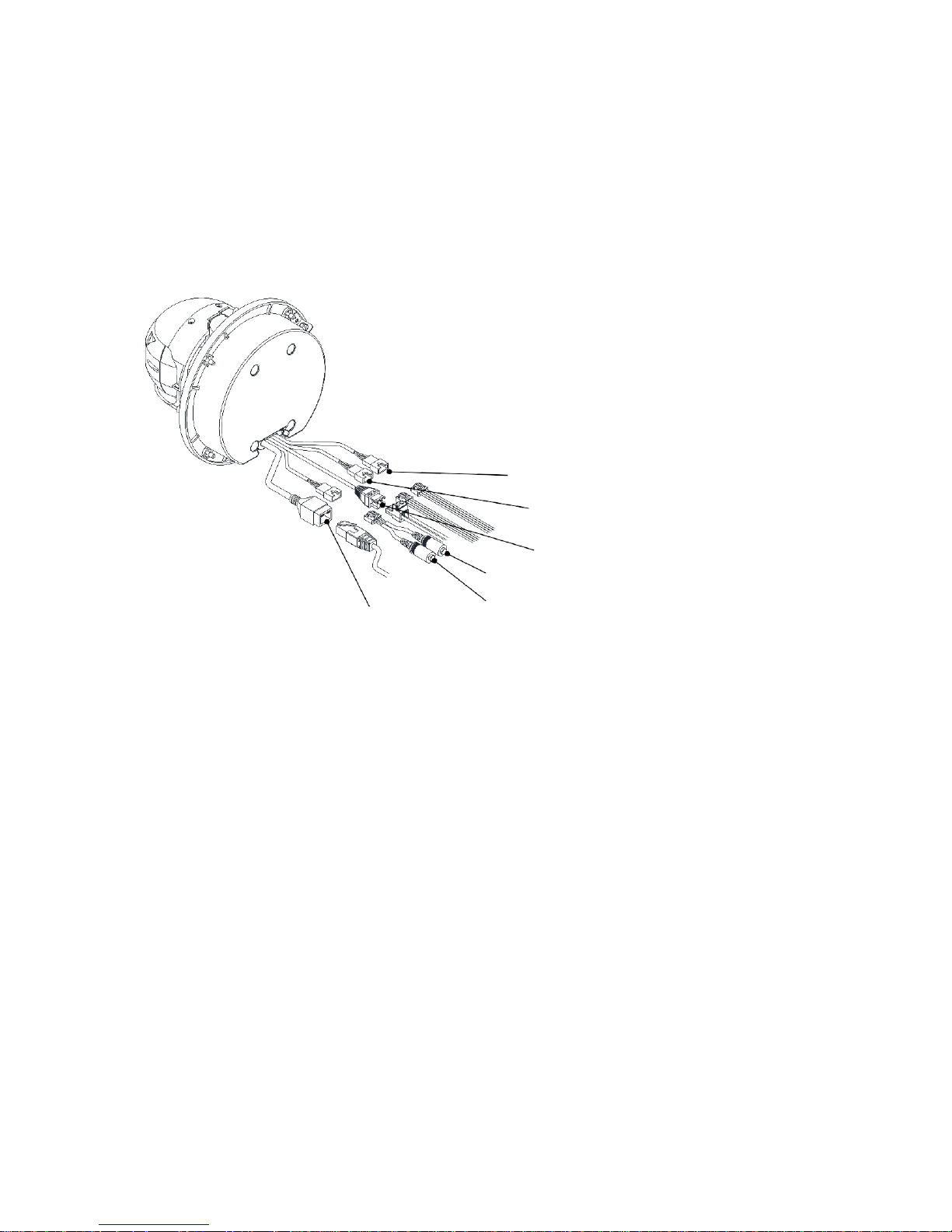
Part Names and Descriptions
⑥Alarm In
⑤
Alarm Out
④
Power
③
Audio Out (White)
①Network
②Audio In (Black)
1.
Network Connector
This PTZ Camera series connects to the network via a standard network cable, and automatically detects the
speed of the local network segment (10BaseT/100BaseTX Ethernet). This socket must be used to power the PTZ
Camera series via Power over Ethernet (PoE). The camera auto- senses the correct power level when using a PoE
(IEEE802.3at) switch, router or injector.
2.
Audio In
Audio in (line level), for line-in mono signal (only left channel is used from a stereo signal)
3.
Audio Out
The Audio output (line level), which could be connected to a line output an active speaker with a built-in
amplifier.
4.
Power Connector
24VAC power connector
5.
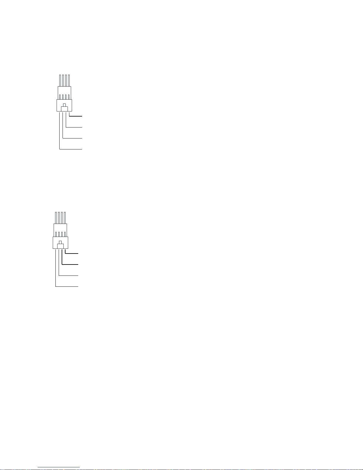
Alarm Out
Two relay output (2A : AC120V / DC24V)
COM (Alarm Out 2)
Alarm Out 2
COM (Alarm Out 1)
Alarm Out 1
6.
Alarm In
Two analog (dry contact) alarm input
COM (Alarm In 2)
Alarm In 2
COM (Alarm In 1)
Alarm In 1
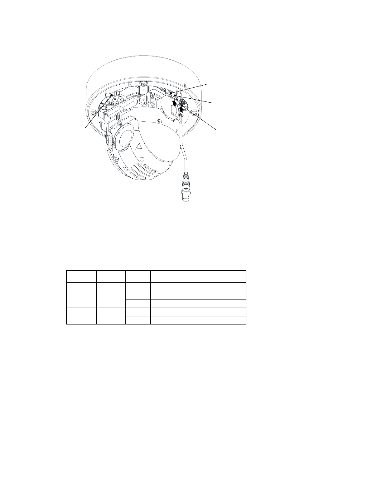
⑦Reset Button
⑧Micro SD card slot
(SDHC Supported)
⑩Status
LED
⑨
Video output
for service monitor
7.
Reset Button
Press this button to restore the camera configuration to its factory default settings.
8.
Micro SD card
Save snapshot images onto a Micro SD card.
9.
Video Output for Service monitor
This analog video output is available when installation mode is set to ON. Use accessory cable
to video output.
10.
Status LED
LED
Color
Indication
System Status
Network
Green
On
Connection to 10/100Mbps Network / LAN.
Flash Indication of network activity.
Unlit No network connection established.
Status
Red
On
Camera is booting up.
Flash Firmware Upload in progress.
Installation Guide
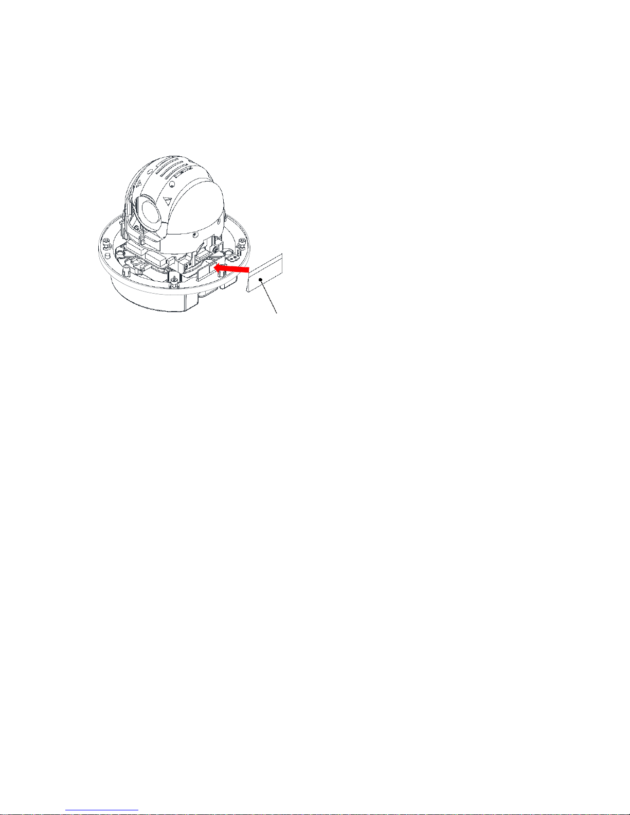
Silica Gel
1. Attach included silica gel accessory to the camera
module with double-sided tape.

Ceiling Installation: Surface Mount
Plastic Anchor(X4)
Gasket Bottom
Case Bottom
1. Punch holes in order to pass
cable through the ceiling. Insert the
gasket into the case bottom and
secure with plastic anchors and
tapping screws.
Tapping Screw M4X30 (X4)
Safety wire
Hex lobe Screw (X4)
2. Connect the camera to the
case bottom with safety wire to
prevent accidents. Tighten the
body connection to the case
bottom with Hex lobe (T20)
screws.
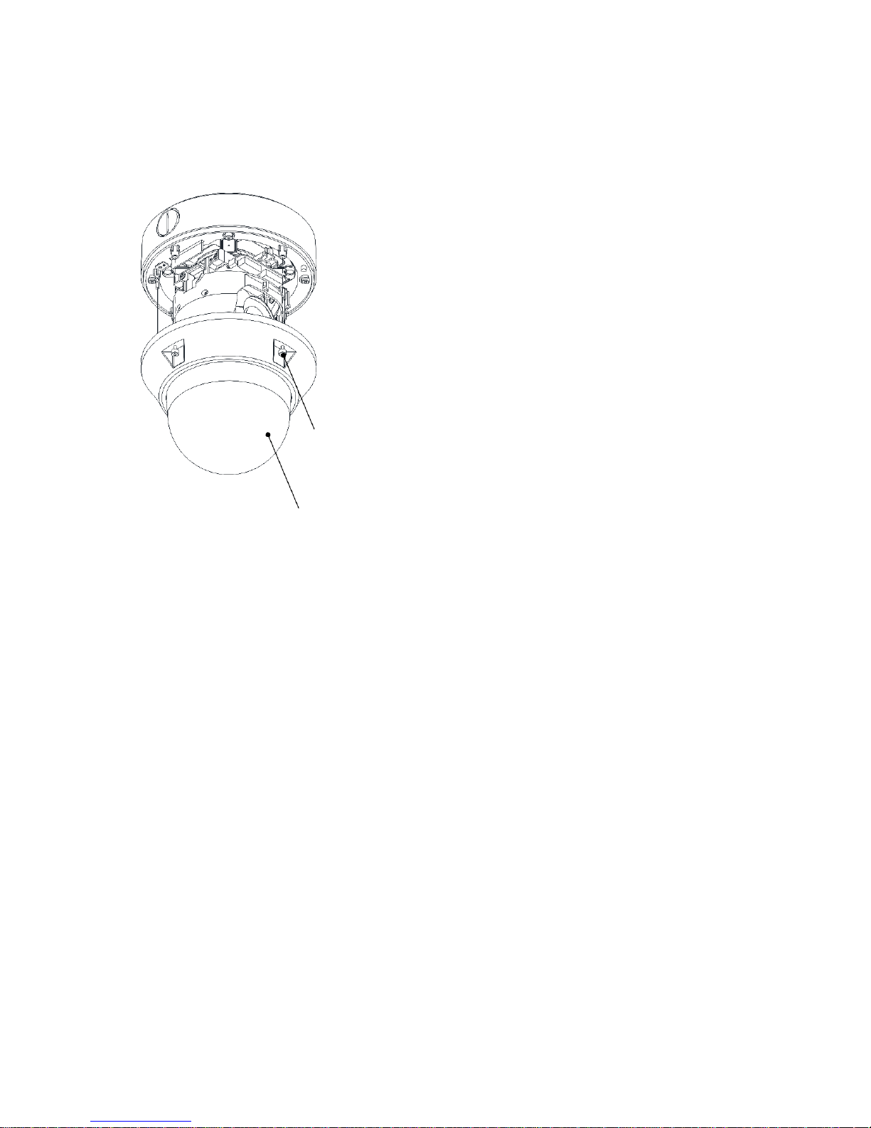
3. Secure the dome cover to the case bottom
with Hex lobe (T20) screws.
Hex lobe Screw (X4)
Dome Cover
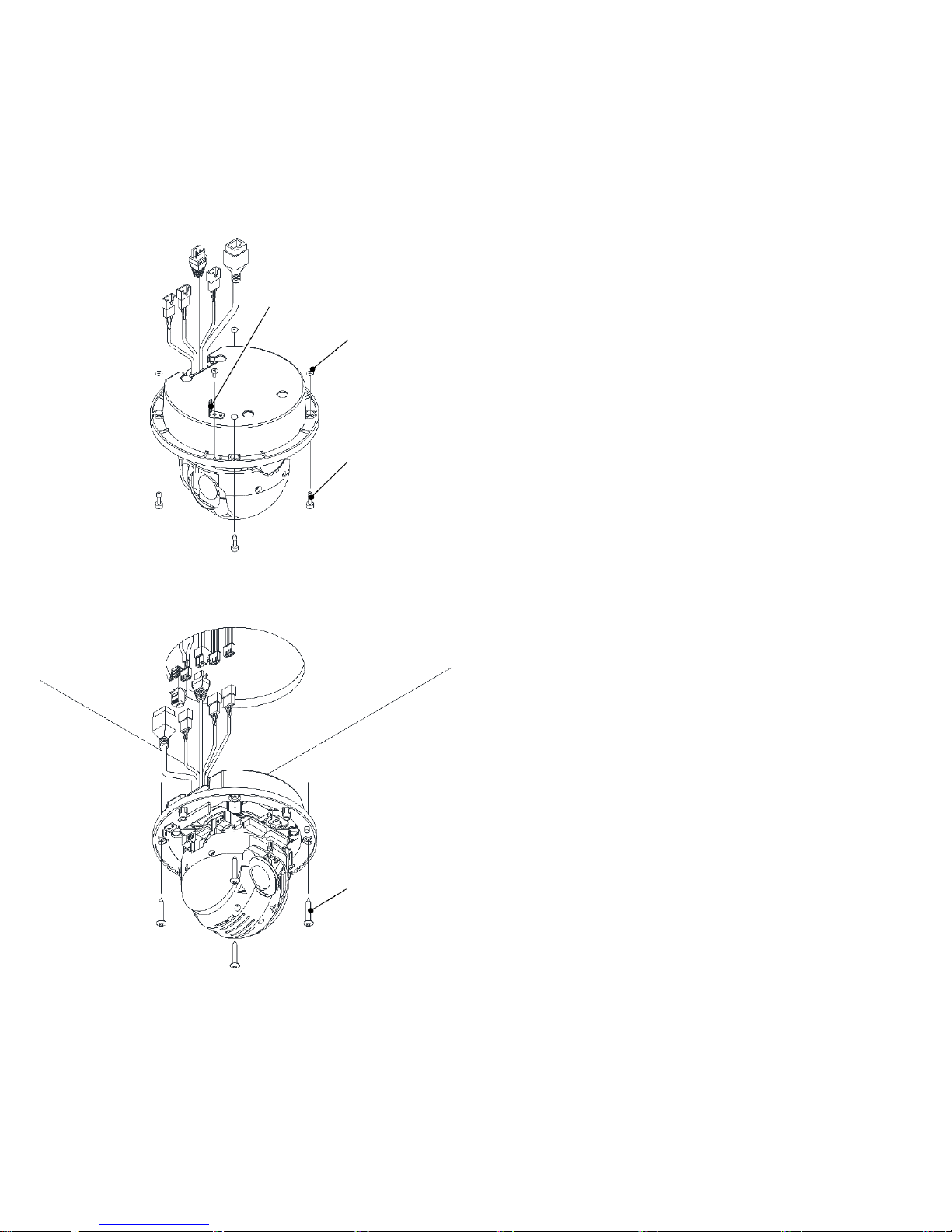
In-Ceiling Installation: In-ceiling Mount
Bracket Safety wire
O-ring (X4)
1.
Separate bracket safety wire, hex lobe screws,
and O-rings from product body.
Hex lobe Screw (X4)
2.
Drill a hole in the ceiling for the main body (Ø 136mm). Connect
the body to the ceiling with tapping screws after connecting the
cables through the hole.
Tapping Screw
M4X30 (X4)
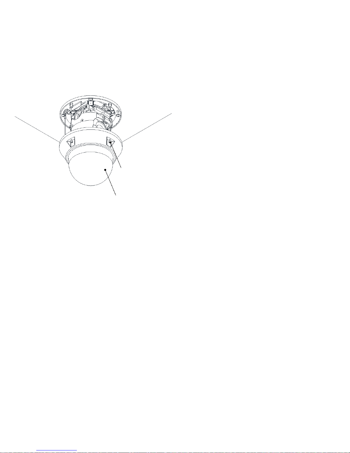
3. Align the dome cover with the case bottom and
secure with Hex lobe (T20) screws.
Hex lobe Screw (X4)
Dome Cover
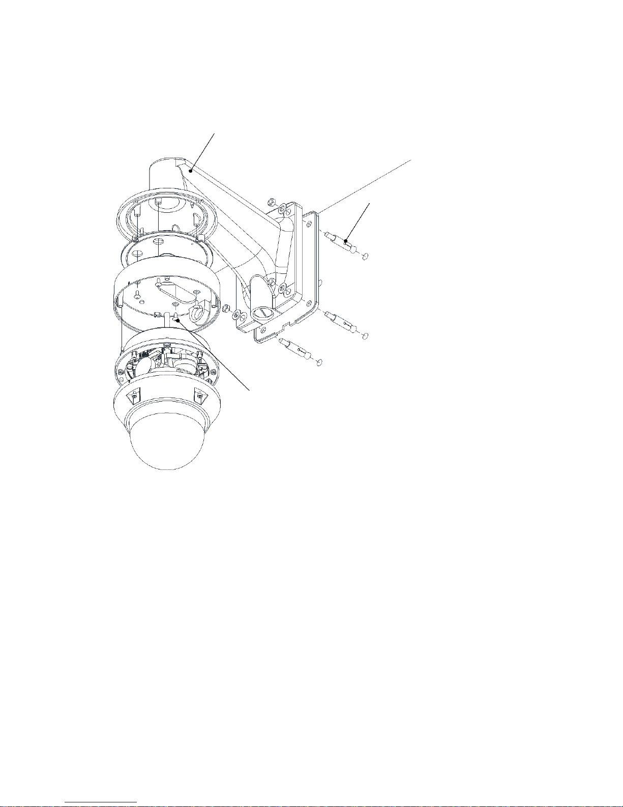
Wall Installation: Wall Mount (Option)
Wall Mount Bracket
Anchor Bolt (X4)
Machine Screw M4X10 (X4)
1.
Affix the wall mount bracket to the wall with anchor bolts.
2.
Put gasket in the case bottom and secure to the wall mount bracket with machine screws.
3.
After connecting the cables secure the case bottom to the module.
4.
Secure dome cover.

Ceiling Pendant Installation: Ceiling Mount (Option)
Anchor Bolt(X4)
Ceiling Mount Bracket
Machine Screw M4X10(X4)
1. Affix the ceiling mount bracket to the ceiling with anchor bolts.
2. Put gasket in the case bottom and secure to the ceiling mount bracket with machine screws.
3. After connecting the cables secure the case bottom to the module.
4. Secure dome cover.

Sun-shield Installation: Sun shield Mount (Option)
Wall Mount Bracket
Ceiling Mount Bracket
Machine Screw M3X10 (X4)
Sun Shield
Mount Adaptor
1. Turn mount adaptor in wall or ceiling mount bracket counterclockwise to remove.
2. Join sun shield to mount adaptor with machine screw (flat head).
3. Re-connect with wall or ceiling mount bracket
4. After connecting the cables secure the case bottom to the module.
5. Secure dome cover.
2. Accessing the Camera

Follow the instructions in the IP Camera Installation Guide to install the camera. This IP Camera can be
accessed on most standard operating systems and web browsers. For the best performance, Windows 7
and Internet Explorer 9 (32bit) is recommended.
2.1 Access from a Browser
1. Open a web browser (Internet Explorer 9 32 bit recommended).
2. Enter the IP address or host name of the IP Camera in the Location/Address field of the browser and
press Enter.
3. A dialog box will pop up to Log-In. The default user name is ADMIN and the default password is
1234.
4. The IP Camera’s Live View will now be displayed on the web browser.
Note: The layout of the live view page for the IP Camera may have been customized to meet specific requirements.
Consequently, some of the examples and functions featured here may differ from a user’s experience.
2.2 Accessing the IP Camera from the Internet
Once installed, the IP Camera is accessible on the Local Area Network (LAN). Configure the
router/firewall to allow incoming data traffic to access the IP Camera from the Internet. For security
reasons, this is usually done through a specific port. Please refer to the router/firewall documentation for
further information and instructions.
2.3 Adjusting the Image
To adjust the position of the lens:

1. Open the Live View page in a web browser. Select the Setup tab and open the Installation page.
Select Video Format.
2. Connect an analog monitor to the Video Out with a BNC cable. Use the image to confirm the
camera is position properly.
3. Check and confirm the image is set as desired on the Lenz Adjustment in Live View page.
2.4 Live View
PC(Client) Speaker
PC(Client) Microphone
Digital Zoom
Snap Shot
Full Screen
Video Stream change: First stream Second stream
Play: Click this button by manually to start the stream
Stop: Click this button by manually to stop streaming
NOTE: It is possible that not all the buttons described below will be visible unless the Live View page has been
customized to display them.

2.5 Video Stream Types
H.264 Protocols and Communication Methods:
o Real-time Transport Protocol (RTP): RTP is a protocol that allows programs to manage the real-
time transmission of multimedia data, via unicast or multicast.
o Real Time Streaming Protocol (RTSP): RTSP serves as a control protocol to negotiate the type of
transport protocol to use for the stream. RTSP is used by a viewing client to start a unicast session.
o User Datagram Protocol (UDP): UDP is a communications protocol that offers limited service for
exchanging data in a network that uses the Internet Protocol (IP). UDP is an alternative to the
Transmission Control Protocol (TCP). The advantage of UDP is that it is not required to deliver all
data and may drop network packets when there is network congestion. This is suitable for live video
as there is no point in re-transmitting old information that will not be displayed anyway.
o Unicasting: Unicasting is communication between a single sender and a single receiver over a
network. This means that the video stream goes independently to each user and each user gets a
personal stream. A benefit of unicasting is if one stream fails it only affects one user.
o Multicasting: Multicasting is a bandwidth-conserving technology that reduces bandwidth usage by
simultaneously delivering a single stream of information to multiple network recipients. This
technology is used primarily on delimited networks (intranets) as each user needs an uninterrupted
data flow and should not rely on network routers.
2.6 How to Stream H.264
Deciding on the combination of protocols and methods to use depends on user viewing requirements a
local network properties. Setting the preferred method(s) is done on the Setup page.
o RTP+RTSP: This method (actually RTP over UDP and RTSP over TCP) should be the first
consideration for live video, especially when it is important to always have an up-to-date video
stream, even if some of the images are lost due to network problems. This can be configured as
unicast or multicast.
o RTP/RTSP/Multicasting: This provides the most efficient use of bandwidth, especially when there
are large numbers of clients connecting simultaneously. Note, however, that a multicast broadcast
cannot pass a network router unless the router is configured to allow this. For example, it is
impossible to multicast over the Internet.
o RTP/RTSP/Unicasting: This should be used for video-on-demand broadcasting so that there is no
video traffic on the network until a client connects and requests the stream. However, as more and
more unicasts clients connect, the traffic on the network will increase and may cause congestion.
Although there is a maximum of 8 unicast viewers, note that all multicast viewers combined count
as 1 unicast viewer.
o RTP/RTSP: This unicast method is RTP tunneled over RTSP. This could be used to exploit the fact
that it is relatively simple to configure firewalls to allow RTSP traffic.
3. Setup
Administrators with unrestricted access can configure the IP Camera in the web browser through the
Setup tab.
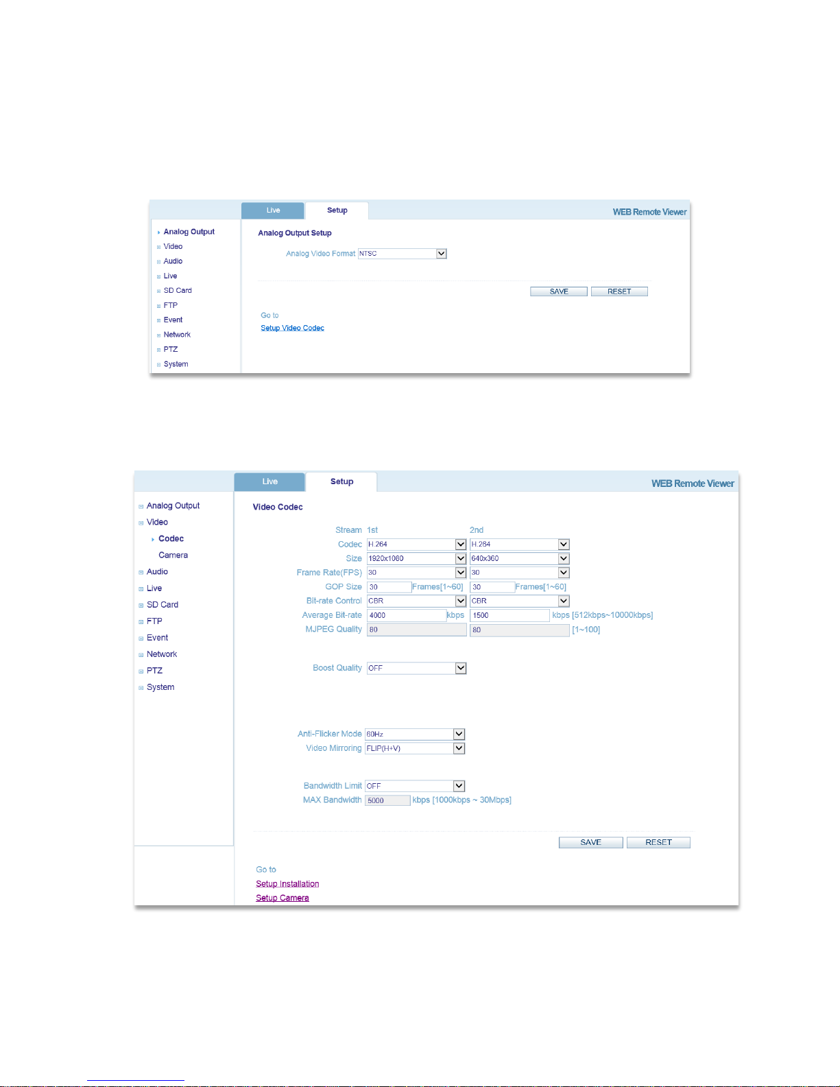
3.1 Analog Output
Toggle the Analog Output ON to connect via BNC output or toggle OFF and click SAVE.
[Not all IP Cameras have an Analog Output]
3.2 Video
3.2.1 Codec
These are tools to control the camera network streams, adjust network stream video quality settings,
and control the video bit rate.
o Codec: H.264 and MJPEG are supported. Both streams cannot be set to MJPEG. Note that
NONE is also a selection for the 2nd Stream.

H.264 is a video compression standard that makes good use of bandwidth and which
can provide high-quality video streams at less than 1 Mbit/s. The H.264 standard
provides scope for a large range of different coding tools for use by various
applications in different situations, and the IP Camera provides certain subsets of
these tools. Using H.264, it is also possible to control the bit rate, which in turn
allows the amount of bandwidth usage to be controlled.
o Size: Video output resolution.
o Frame Rate (FPS): Choose the number of image frames per second, from 1-30fps in
normal mode or 1-15fps when slow shutter mode is enabled. If slow shutter mode is enabled
and the low light condition is met, the frame rate automatically goes down to half of the
normal mode setting.
o GOP Size: The GOP Size can be set from 1-60 frames.
o Bit-rate Control: When using H.264 compression, if there is only a limited amount of
bandwidth available a constant bit-rate (CBR) is recommended, although this may
compromise image quality. Use a variable bit-rate (VBR) for the best possible image quality.
o Average Bit-rate: Can be set from 512Kbps-10Mbps.
Recommended bit-rate for D1: 800Kbps-1Mbps
Recommended bit-rate for 1.3M (720p): 3Mpbs-4Mbps
Recommended bit-rate for 2M (1080p): 6Mbps-8Mbps
o MJPEG Quality: If a stream is set to use the MJPEG compression codec, the quality of the
MJPEG codec can be set from 1-100, where 100 is the highest quality.
o Boost Quality: If Boost Quality is set to ON, the Boost FPS and Boost GOP Size can be set.
If there is motion in the camera’s field, the image quality will increase using these settings.
o Anti-Flicker Mode: Set to 60Hz for NTSC, or 50Hz for PAL. For usage when the camera is
installed in locations lit by fluorescent lighting.
o Video Mirroring: Choose NONE for no video mirroring, HORIZONTAL for horizontal
video mirroring, VERTICAL for vertical video mirroring, or FLIP for horizontal and vertical
video mirroring.
o Bandwidth Limit: If set to ON, the maximum bandwidth can be set from 1000Kbps-30Mbps.
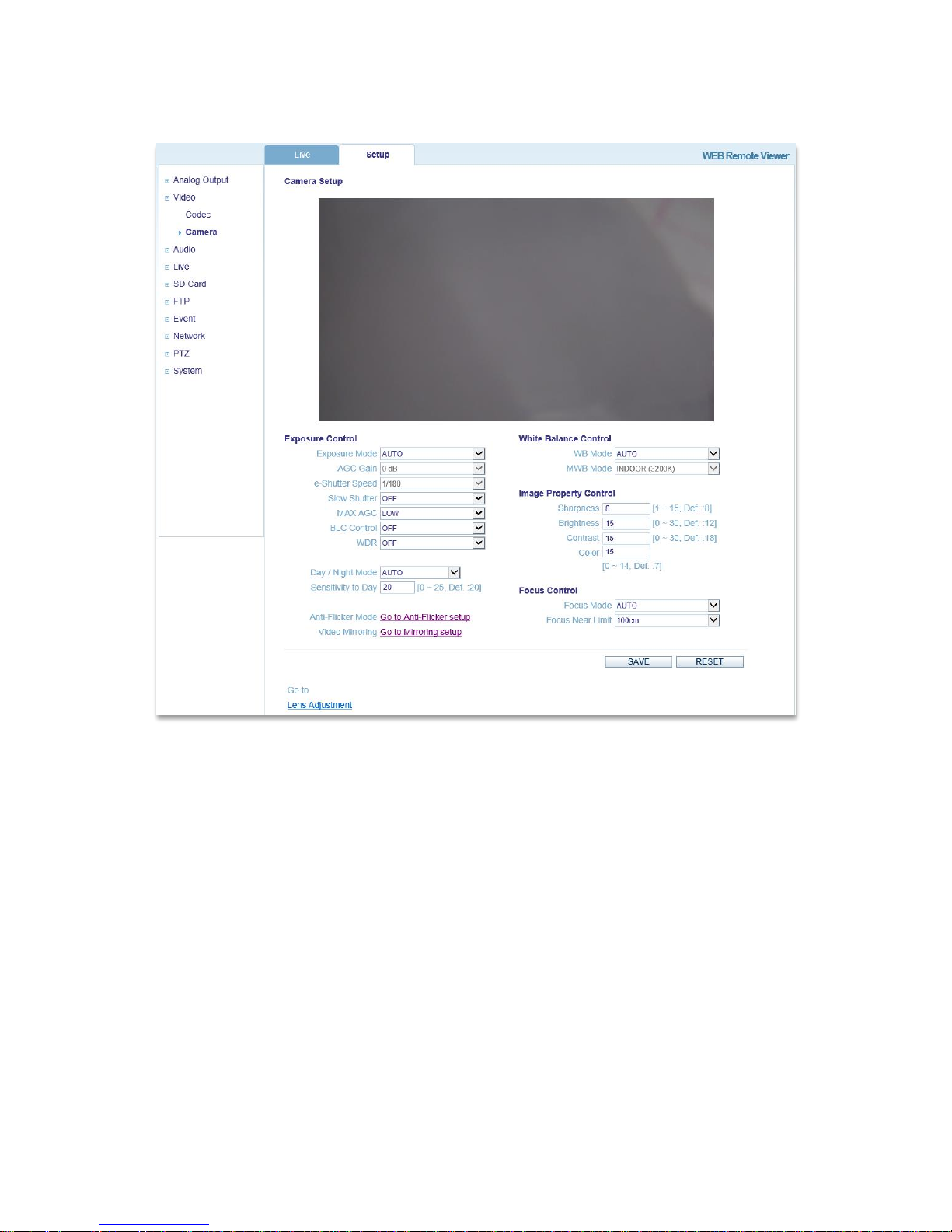
3.2.2 Camera
This section allows various camera settings to be adjusted.
o Exposure Control:
Exposure Mode: Set to AUTO for automatic exposure control, or MANUAL to
control the camera exposure manually.
AGC Gain: If Exposure Mode is set to MANUAL, AGC Gain can be set from 0-
28dB. For low light conditions, adjust to a higher value.
e-Shutter Speed: If Exposure Mode is set to MANUAL, e-Shutter Speed can be set
from 1/30-1/10000.
Slow Shutter: Can be turned on for low light conditions; can be set to x2, x4, or x8.
MAX AGC: Max Automatic Gain Control can be set to LOW, or HIGH.
BLC Control: Back Light Compensation control. This adjusts the exposure of
scenes with strong backlight in the center-bottom of the image. When the image
background is too bright or the subject is too dark, backlight compensation makes the
subject appear clearer. The settings for low light behavior determine how the camera
behaves at low light levels. These settings affect video image quality and how much
noise is in the images. This can be set to ON, or OFF.
WDR: Wide Dynamic Range (WDR) is a feature that allows for different objects at
different exposures to be viewed in the same scene (ex; one object in a bright area
and one in a dark area). When WDR is activated the FPS setting will automatically
drop by fifty percent. ON(Histogram): The video image is analyzed via histogram to

gradually adjust the exposure between bright and dark areas. Auto(Low Detection):
Only used when the difference between bright and dark areas is severe. Auto(Middle
Detection): Used when the difference falls under normal levels. Auto(High
Detection): WDR will automatically activate even when the difference between
bright and dark areas isn't severe.
Day/Night Mode: If set to AUTO, the camera will automatically switch according to
current lighting conditions that persist for a set period of time. The mode can also be
set to specifically DAY or NIGHT, as well as SCHEDULE.
o White Balance Control:
WB Mode: Can be set to MANUAL, or AUTO. This is used to make the colors in
the image appear consistent, compensating for the different colors present in different
light sources. The IP Camera can be set to automatically identify the light source and
compensate accordingly.
MWB Mode: If white balance is set to MANUAL, the light source can be manually
added, such as INDOOR (3200K), or OUTDOOR (5800K).
o Image Property Control:
Sharpness: Modifies the video signal sharpness. Default: 8, Range: 1-15
Brightness: Modifies the video signal brightness. Default: 12, Range: 0-30
Contrast: Modifies the video signal contrast. Default: 18, Range: 0-30
Color: Modifies the video signal color. Default: 7, Range: 0-30
o Focus Control:
Focus Mode: Focus Mode can be set to Auto, Auto-Semi, and Manual. MANUAL :
User manually focuses the lens. AUTO: The camera will automatically focus the
lens. AUTO(semi): Camera will automatically focus one time when user controls the
PTZ camera. After the PTZ operation is complete the camera will not refocus in
accordance to change in luminance or position.
Focus Near Limit: Focus can be set to be restricted to a distance within the set
focus value. This can be set to 100CM, or 30CM.
3.3 Audio
Choose to enable or disable the audio function, which uses the G.711 u-law codec at 8 KHz. The
microphone and speaker volume can also be adjusted.

3.4 Live
3.4.1 Setup
This section allows for general viewer settings to be adjusted.
o Viewer Setup:
LiveView Protocol: Choose which protocol to use for live video. RTP Unicast
(UDP), RTP Multicast (UDP), or RTP over RTSP (TCP) can be selected.
Buffering Time: Buffering time can be set for a number between 0-90 times 1/30
seconds, or a range of 1-3 seconds.
o Viewer OSD Setup:
Resolution: Toggle OSD Resolution ON/OFF.
Date/Time: Toggle OSD Date/Time ON/OFF.
Event State: Toggle OSD Event State ON/OFF.
3.4.2 Privacy Mask
The IP Camera can support the privacy mask feature so a portion of the frame can be blocked based on
personal preference of legal requirements. Select the Area and Color and click Save.

3.5 SD Card
3.5.1 Config
This section is provided to set up an SD Card for recording images.
o SD Card Configuration:
Overwriting: Enable or Disable the SD Card function for recording images.
SD Status: Check the status of the SD Card.
SD Safety Remove: Unmount any SD Card before removal and mount when
inserting an SD Card.
Erase Image Files: Delete image files on the SD Card.
3.5.2 Event
This page is for configuring whether or not to write images to an SD card when an event occurs.

o Event SD Writing:
SD Writing: Choose whether to Enable or Disable this function.
Directory: Input the desired file path on the SD Card for the uploaded images.
File Prefix: Input the desired file name prefix (for example, alm_).
SD Write Mapping: Choose whether to write images during Alarm In, and/or
Motion.
Effective Period: Choose whether to always write images when an event occurs or
during a user-defined schedule.
3.5.3 Periodical
This page is for configuring whether or not to periodically write images from the camera to an SD card.
o Periodical SD Writing:
SD Writing: Choose whether to Enable or Disable this function.
Directory: Input the desired file path on the SD Card for the uploaded images.
File Prefix: Input the desired file name prefix (for example, per_).
Interval: Choose the desired image write interval, from 10 seconds to 1 hour.
Effective Period: Choose whether to always write images when an event occurs or
during a user-defined schedule.
3.6 FTP

3.6.1 Config
This section is provided to set-up a FTP (File Transfer Protocol) server so the IP Camera can send
recorded images to the server.
o Server Configuration:
FTP Server: Enable or Disable the FTP Server function for downloading recorded
images.
o Client Configuration:
Server IP: Enter the desired FTP Server’s IP address.
Port: Enter the desired FTP Server’s Port number. Default: 21, Range 1025-65535.
User name: Enter the FTP Server client user name.
Password: Enter the FTP Server client password
Send Mode: Choose whether the send mode is Active or Passive.

3.6.2 Event
This page is for configuring whether or not to send images to an FTP server when an event occurs.
o Event FTP Sending:
FTP Sending: Choose whether to Enable or Disable this function.
Directory: Input the desired file path on the FTP server for the uploaded images.
File Prefix: Input the desired file name prefix (for example, alm_).
FTP Send Mapping: Choose whether to write images during Alarm In, and/or
Motion.
Effective Period: Choose whether to always upload images when an event occurs or
during a user-defined schedule.

3.6.3 Periodical
This page is for configuring whether or not to periodically upload images from the camera to an FTP
server.
o Periodical FTP Sending:
FTP Sending: Choose whether to Enable or Disable this function.
Directory: Input the desired file path on the FTP server for the uploaded images.
File Prefix: Input the desired file name prefix (for example, per_).
Interval: Choose the desired image upload interval, from 10 seconds to 1 hour.
Effective Period: Choose whether to always upload images when an event occurs or
during a user-defined schedule.
3.7 Event
3.7.1 Alarm Port
This page is designed to allow for enabling/disabling the IP Camera’s Alarm Input/Output.

3.7.2 Motion
This page is designed to allow for different motion areas to be selected and saved. Select an area and
use the mouse to click and drag the desired area, then click Save.
3.7.3 Mapping
This page is designed to allow a user to select whether or not to have an e-mail notification sent to
specified users if Alarm In or motion event occurs.
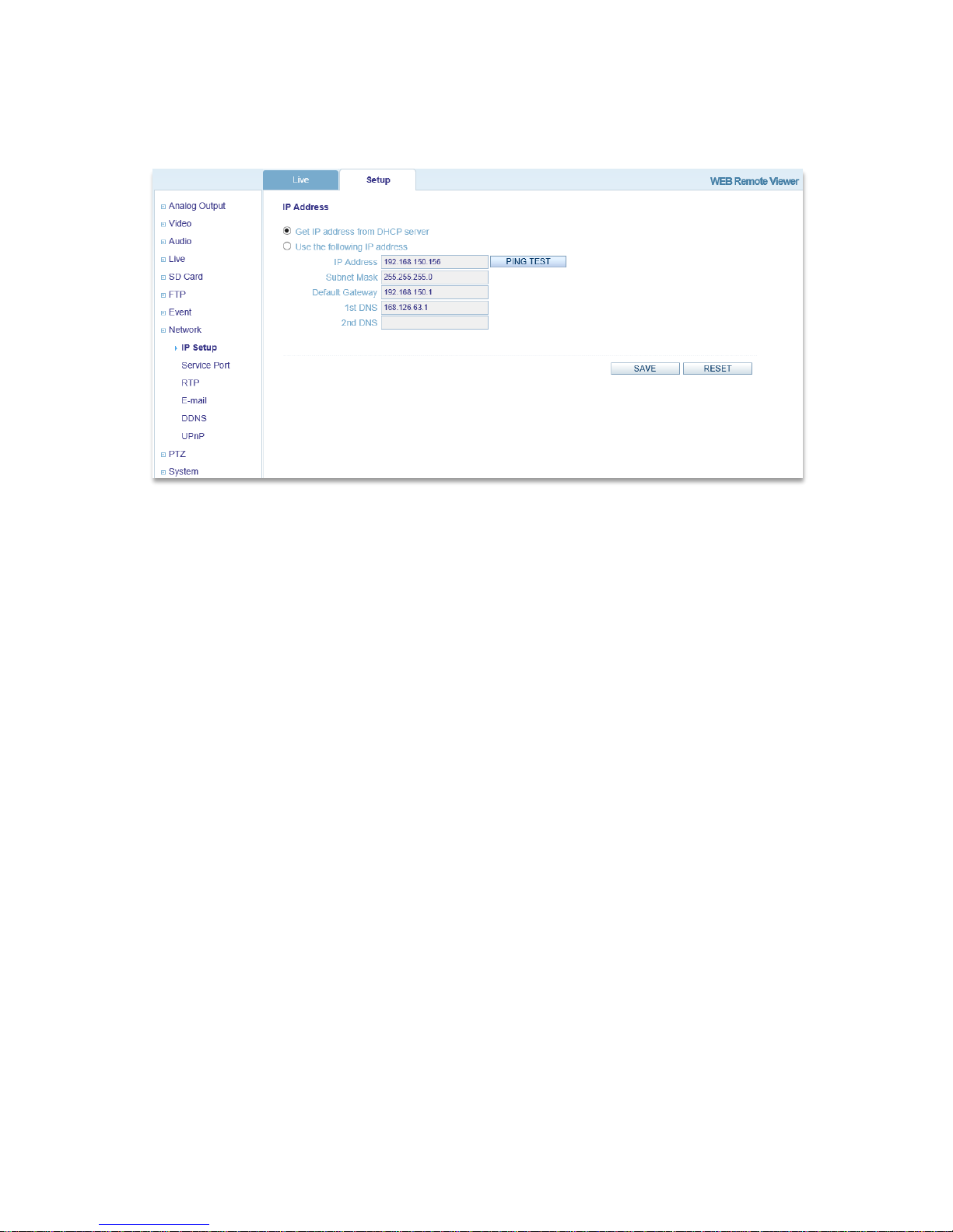
3.8 Network
3.8.1 IP Setup
This page allows for current network settings to be configured, specifically the IP Camera’s IP address.
The IP Camera supports IP version 4, which allows the IP address to be set automatically via DHCP
(Dynamic Host Configuration Protocol) or manually via a Static IP address. DNS (Domain Name
Service) configuration provides the translation of host names to IP addresses on the network. If the
DHCP server can update the DNS server, it is possible to access the IP Camera by a host name which is
always the same, regardless of the IP address. The 1st DNS is the IP address of the primary DNS server
on the network and the 2nd DNS is the IP address of the secondary DNS server, which is used if the
primary DNS server is unavailable.
By default, the IP Camera is set to get the IP address from the DHCP server and UPnP is enabled. If the
network has a DHCP server and the UPnP function is enabled on a PC, it is possible to find the IP
Camera in “My Network”.
If a DHCP server is not available on the network, please assign the IP address as follows:
o Execute Admintool.exe and click the ‘Search’ button.
o Select the camera after it appears in the camera list.
o Type in all of the network information.
o Click the ‘Apply’ button and the settings will appear in the list.
o Click the ‘Setting’ button to set network information for the IP Camera.

When you double-click the camera in the list, the default web browser (Internet Explorer or compatible
equivalent) will open and automatically connect to the IP Camera.
3.8.2 Service Port
This page is for setting the IP Camera port numbers.
o Service Port:
HTTP Port: Input a desired HTTP (Hyper Text Transfer Protocol port number).
RTSP Port: Input a desired RTSP (Real Time Streaming Protocol port number).
o Port Forwarding:

Port Forwarding: Select AUTO to automatically set the connection ports of the
router. Note: UPnP must be supported by the router.
External IP: If Port Forwarding is successful, the external IP address for the IP
Camera will be displayed. This is the address that can be used to access the IP
Camera.
3.8.3 RTP
This page is for defining RTP (Real-Time Transport Protocol) settings for the IP Camera. RTP is used
for delivering audio and video over an IP network, including multiple destinations through multicast.
o RTP Port Range:
Start Port: Enter the desired Start Port number.
End Port: Enter the desired End Port number.
o Multicast Setup:
Enter the IP addresses, Video Port numbers (even values only), Audio Port numbers
(even values only), and TTL values for each stream.

3.8.4 E-mail
This page allows users to toggle e-mail notification and specify which e-mail server is used. By default,
a user can toggle notifications on and the default e-mail server will function without further setting
required.
o E-mail Setup:
Notification: Toggle e-mail notification ON/OFF.
Frequency: Select the frequency of e-mail notifications. Range: 1-60 minutes.
Server: If not using the default server, input the address of the desired server.
Port: If not using the default server, input the SMTP port number of the desired
server. Default value: 25
Security: Toggle SSL or TLS security ON/OFF.
User: If not using the default server, input the user name for accessing the e-mail
server.
Password: If not using the default server, input the user password for accessing the
e-mail server.
From: Input the name that will display before the e-mail address when receiving a
notification.

3.8.5 DDNS
This page allows a user to enable or disable DDNS (Dynamic Domain Name System) and select an
address to be used for connecting to the IP Camera.
o DDNS Setup:
DDNS: Toggle DDNS ON/OFF.
User Set URL: Input a domain name to connect to the IP Camera (for example,
http://ipcamera.dvrlink.net)
3.8.6 UPnP
This page is for toggling UPnP (Universal Plug and Play) on or off. It is ON by default.

3.9 PTZ
3.9.1 Preset
General PTZ functions can be setup on this page.
o Preset Freeze: Freeze video before moving to Preset and resume after Preset movement
completed.
o Power Up Action: Automatically continue from Scan/Tour from prior operation if unit
completes booting action.
o Parking Action: Run the specified action after a user-specified period of time when there are
no Pan, Tilt, Zoom operations.
o Wait Time: Wait Time is the waiting time before engaging Parking Action when PTZ is not in
operation.
o PTZ Action: Action is executed after a set wait time.
Preset Select: Select Preset to run.
Latest Action: Run most recent action.

3.9.2 Preset
Preset is a pre-defined camera view than can be quickly and easily moved to and
viewed, simply by selecting the preset.
o Preset: select preset Number.
o Name: Input preset Name.
o Show Advanced: Day/Night Focus Setup windows pops up.
o Save: Specified value Saved.
o Move: Run preset.
o Delete: Specified value Deleted.
o Delete All: All Preset value Deleted.

3.9.3 Scan
Scan displays the video stream from different preset positions.
o Name: Up to 15 characters can be used to set a Scan name.
o Number: 1-12 can be set (no duplication)
o Speed: Preset interval movement speed.
o Dwell Time: The waiting time between moving to the next Preset.
o Preset: Can select one from previously set Presets. Preset1(From) / Preset2(To)
o Direction: The direction of Scan movement can be set.AUTO, CW or CCW
o Add/Del: Press the Add button to add new Scans or Delete to delete Scans (must click Save to
apply).
o Run: Run Scan.
3.9.4 Tour
Set the camera movement. Preset, Scan, and Tour can be selected to fulfill
one entire Tour.
o Tour Speed: Sequence movement speed.
o Sequence: Consists of Sequence members (Preset, Scan, Tour) and Dwell Time.

3.9 System
3.9.1 User
This page is for user management: adding new User IDs within a specific group and specifying the
user’s password, e-mail address, and whether or not the user should receive e-mail notifications. A user
may also be deleted. The Admin group allows users to change settings and view live streaming video.
The User group only allows users to view live streaming video.
3.9.2 Date/Time
This page configures the IP Camera date and time settings.
o Date/Time Setup:
Current Server Time: This displays the IP Camera’s current system time and date.
Date Format: This allows the display format for the date to be changed.
Time Format: This allows for the display format for the time to be changed between
12 hour and 24 hour timekeeping systems.
NTP Server: If ‘Synchronize with NTP server’ is selected, input the NTP server
address.
Local Time: If ‘User set manually’ is selected, input the time manually or sync with
a PC.
Time Zone: Select the IP Camera’s time zone.
DST: Toggle Daylight Savings Time ON/OFF.

3.9.3 Maintenance
This page is for important system maintenance for the IP Camera.
o Maintenance:
System Name: Input the desired name for the IP Camera.
System Reboot: Reboots the IP Camera if clicked.
Factory Default: Resets all IP Camera settings to original factory settings if clicked.
Save/Load PTZ Data: PTZ Setup Status (Preset, Scan, Tour…) Save or Load.
Enable Firmware Upgrade: Must be clicked prior to performing a firmware
upgrade.
Firmware Updates: Browse the network directory for a firmware file and press OK
to update the IP Camera firmware.
3.9.4 Information
This page displays some important information about the IP Camera.

Underwriters Laboratories Inc. (“UL”) has not tested the performance or reliability of the security
or signaling aspects of this product.
UL has only tested for fire, shock or casualty hazards as outlined in UL’s Standard(s) for Safety,
UL60065.
UL Certification does not cover the performance or reliability of the security or signaling aspects
of this product.
UL MAKES NO REPRESENTATIONS, WARRANTIES OR CERTIFICATIONS WHATSOEVER
REGARDING
THE PERFORMANCE OR RELIABILITY OF ANY SECURITY OR SIGNALING RELATED
FUNCTIONS OF THIS PRODUCT.
The apparatus shall not be exposed to dripping or splashing and that no objects filled with
liquids, such as vases, shall be placed on the apparatus
"WARNING: To Reduce the Risk of Fire or Electric Shock, Do Not Expose This Apparatus to
Rain or Moisture"
4. Accessory List
Accessory List
Item
Description
IP Camera
IP PTZ Camera, 1EA
CD
User Manual CD, including product documentation, installation tools, and other
software
Printed Installation Guide
Quick Guide for installation
Accessories
Silica gel
Tapping Screw (M4x30)
Plastic Anchor
Wrench (Hex 2.5mm)
Power Terminal Block
Analog Video Cable
Alarm Out Cable
Alarm In Cable
Audio Cable
 Loading...