


Network Video Recording
Surveillance System
User Manual
※
The picture & functions & supplied items might differ according to the specification and model.
※
Contents of this user manual are protected under copyrights and computer program laws.
Model : OR-iNVR08 & OR-iNVR16
Please read this User Manual and retain it for future reference.

WARNING
TO REDUCE FIRE OR SHOCK HAZARD,
DO NOT EXPOSE THE UNIT TO RAIN OR MOISTURE.
The installation should be made by a qualified service person
and conformed to all local codes.

3333
Cautions
Read Before System Operation
Follow these details to prevent material damage or personal injury.
Signs of Caution and Warning
Warning: This sign indicates that the user could die or be seriously wounded if not used or installed
properly.
Caution: This sign indicates that the user could be wounded or could expect property damage if not
used or installed properly.
Warning: Do not expose the product to fog, rain or too much humid to decrease danger from electric
shock or fire.
General Warning
Warning
1. Use the power cord, which is supplied or recommended by the supplier, or
it may cause fire.
2. Do not disassemble or reassemble the product.
It may cause malfunction or fire.
3. Enquire to your vendor for repair.
It may cause electric shock or fire if the repair is not done properly.
4. Do not touch the product with wet hands.
It may cause malfunction or electric shock.
5. Product installation must be ensured to a professional for product installation, or
it may cause malfunction, electric shock or fire.
6. Ground applies to video products equipped with a 3-wire grounding type plug having a third (grounding) pin.
This plug only fits into a grounding-type power outlet.
If grounding is not done, it may cause malfunction or electric shock.
7. Ground connection must not touch gas pipe, water pipe or telephone line.
If grounding is not done properly, it may cause electric shock.
8. Prevent metallic foreign substance from going inside the product.
It may cause malfunction or electric shock.
9. Do not spray insecticide or flammable spray while driving.
It may cause fire.
10. Place the system in a open place where air ventilation is guaranteed, or
it may cause over-heating and seriously damage the system to be fired.
11. Prevent water from instilling inside electrical parts.
Clean with a dry towel or malfunction or electric shock could result.

Caution
1. Use the power cord, which is supplied or recommended by the supplier.
The internal fan rotates at high speed and may cause an accident.
2. Do not drop, give strong vibration, or shock to the product.
It may cause malfunction.
3. The air inhaler of the front panel and air outlet of the back panel must not be blocked during installation.
The internal temperature of the product would be greater than allowable and could cause malfunction or
fire.
4. Do not touch the product or the power cord when there is thunder.
It may cause electric shock.
5. Do not install the product near or on top of heating source.
The internal temperature of the product would be greater than allowable and could cause malfunction or
fire.
6. Do not install the product on inclined or unstable location or where vibration could be committed.
It may cause malfunction.
Cautions about the Power
Warning
1. Must use the outlet of the grounding to connect the power cord, or
it may cause fire.
2. Do not connect on the middle of power cord or use extension cord.
It may generate heat or cause fire.
3. Do not touch the power cord with wet hands.
It may cause electric shock.
4. Keep power cord dry and protect from humidity.
It may generate heat or cause fire. The power cord is not waterproof.
5. Hold the body of the plug while removing the power plug.
Do not pull the power cord. Damage to the power cord may generate heat or cause fire.
6. Check the power plug regularly.
Humidity and moderation in smoking may cause fire.
7. Remove power cord from outlet when product is not used for a long time.
It may cause short-circuit or electric shock.
Caution
1. Do not turn off the power by removal of the power plug.
To turn off the power, click the power button from the front panel.
When the system stops abnormally, the power button might not work. Click power button for 5 full seconds to turn
power off.
2. Do not cut off the power artificially, or give shock or vibration to unit while the hard disk is activating.
It may cause hard disk failure or loss of data.
Remarks
※
Pictures and buttons are subject to be changed or modified up to different models.
※
Function or configuration is subject to be changed or modified without prior notice for improvement of the product.

1111
Contents
ContentsContents
Contents
1. GETTING STARTED ..................................................................................................................................................................... 2
1.1 Checking Supplied Items.................................... ....................... ....................... ...................... ....................... ....................... ................. 2
1.2 System Requirements ....... ....................... ....................... ....................... ...................... ....................... ....................... ....................... ..... 3
1.3 System Preparation ............................................. ....................... ....................... ...................... ....................... ....................... ................. 3
1.4 System Startup ...................................... ....................... ....................... ....................... ...................... ....................... ....................... ......... 4
1.5 System Shutdown ........................... ....................... ....................... ....................... ...................... ....................... ....................... ............... 7
1.6 Factory Default ........................... ....................... ...................... ....................... ....................... ....................... ....................... ..................... 7
2. INITIAL SETUP(QUICK SETUP) ................................................................................................................................................... 8
3. CUSTOM SETUP ........................................................................................................................................................................ 11
3.1 Video Setup ................................. ....................... ...................... ....................... ....................... ....................... ....................... .................... 11
3.1.1. Registration .................................................................................................. 11
3.1.2. Video Setup .................................................................................................. 12
3.2 Record .................... ....................... ....................... ....................... ...................... ....................... ....................... ....................... .................. 12
3.2.1. Schedule Setup .............................................................................................. 12
3.2.2. Event Setup .................................................................................................. 13
3.2.3. Notification ................................................................................................... 13
3.3 Network .................. ....................... ....................... ....................... ...................... ....................... ....................... ....................... .................. 14
3.4 User Management ........................................ ....................... ....................... ....................... ....................... ....................... ...................... 15
3.4.1. Administrator ................................................................................................. 15
3.4.2. General User ................................................................................................. 15
3.5 System Operation ............................. ....................... ....................... ....................... ....................... ...................... ....................... ............ 16
3.5.1. Date & Time .................................................................................................. 16
3.5.2. HDD Configuration .......................................................................................... 16
3.5.3. Configuration Backup/Restore ............................................................................ 16
3.5.4. Local (USB) Backup ........................................................................................ 16
3.5.5. Firmware Upgrade .......................................................................................... 16
3.5.6. Factory Default .............................................................................................. 17
3.6 Log ................................ ....................... ....................... ....................... ...................... ....................... ....................... ....................... ............ 17
3.6.1. System Log ................................................................................................... 17
3.6.2. Event Log ..................................................................................................... 17
3.7 Live Monitoring .... ....................... ....................... ....................... ...................... ....................... ....................... ....................... .................. 18
3.7.1. Screen Mode ................................................................................................. 18
3.7.2. Setup each Channel ........................................................................................ 18
3.7.3. PTZ Control .................................................................................................. 20
3.8 VOD Monitoring ............................................ ....................... ....................... ...................... ....................... ....................... ....................... 21
4. Q&A ............................................................................................................................................................................................ 22

2222
1.
Getting Started
Thanks for purchasing OR-iNVR.
OR-iNVR is Network Video recorder from various ONVIF™ based IP devices and supports remote playback &
transmission data.
OR-iNVR is working on Java™ platform and provides browser free in monitoring & setup in various WEB
browsers.
1.1 Checking Supplied Items
Make sure that you have following items supplied with your DVR. If any of these items is missing or damaged,
notify your vendor immediately. Keep the packing utilities for moving or storage purposes afterwards.
Items
Photo
Quantity
3333
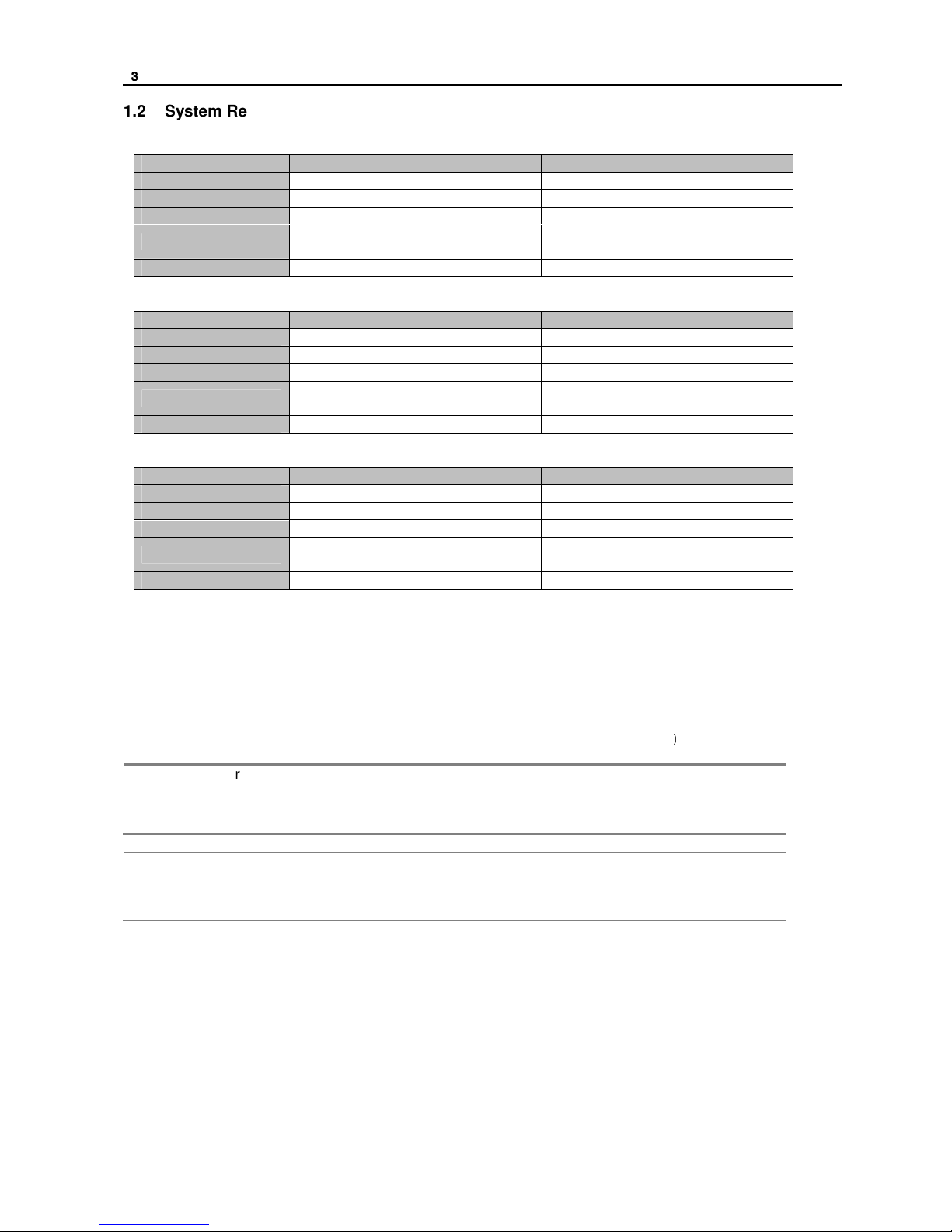
1.2 System Requirements
[Windows OS]
Category Recommended Minimum
OS Windows 7 or higher Windows 7 or higher
CPU Inter 3rd Gen. Core i7 Intel Core i3
RAM 8GB 4GB
VGA
1280x1024 or Higher
(with Independent VGA card)
1366X768 or Higher
(with Independent VGA card)
Java™ Java™ version 7 or Higher Java™ version 6 or Higher
[MAC OS]
Category Recommended Minimum
OS MAC OSX 10.7 or higher MAC OSX 10.7
CPU Intel MAC core i7 Intel core i5
RAM 8GB 4GB
VGA
1280x1024 or Higher
(with Independent VGA card)
1366X768 or Higher
(with Independent VGA card)
Java™ Installed in the OS Installed in the OS
[Linux]
Category Recommended Minimum
OS Linux 2.6 or Higher Linux 2.6 or Higher
CPU Inter 3rd Gen Core i7 Intel Core i3
RAM 8GB 4GB
VGA
1280x1024 or Higher
(with Independent VGA card)
1366X768 or Higher
(with Independent VGA card)
Java™ Java™ version 7 or Higher Java™ version 6 or Higher
1.3 System Preparation
OR-iNVR is working on a Java™ platform, Java™ runtime should be installed in the PC.
If this is not installed in your PC, install Java™.
The latest version of Java™, can be downloaded from the webpage. (http://java.com/)
N
OTE
1) User can install Java™ by clicking “Free JAVA Download” button in the main page of
Java™ homepage.
2) There are two versions of Java™, 32bit edition & 64bit edition. It should be followed to
that of WEB browser edition, not the OS edition.
N
OTE
In case of Windows IE(Internet Explorer), Java™ detects IE version automatically. But, in
case of the other browsers(ex. Google Chrome, etc.), it can be installed as plug-in type and
installation message will be shown in the browser.
4444
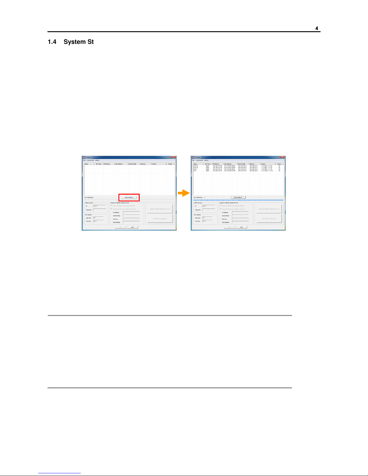
1.4 System Startup
Network setup is necessary before using OR-iNVR.
If you know the assigned IP to OR-iNVR, you can connect to OR-iNVR with the IP and reset it in the setup
screen.
If you don’t know assigned IP, run IP Installer to find devices.(IP installer is included on CD)
*IP Installer & OR-iNVR should be in the same Subnet Mask.
[Device Search]
1. Check if OR-iNVR is placed in same subnet mask with IP Installer.
2. Click ‘Device Search’ button of IP Installer.
*If TCP Port of OR-iNVR was changed, TCP Port for search should be changed before searching
devices.
3. IP Installer shows device list which is connected in the same network.
Note
When you execute IP Installer, Windows may pop up warning message screen. In this
case, you need to click “Yes” to run the program.
If there is no search result shown, even though IP Installer & OR-iNVR uses same
Subnet Mask and OR-iNVR is running, please check if the firewall option is on. In this
case, stop Windows firewall or related program and try it again.
And, IP Installer searches devices with broadcast method. So, please also check if the
firewall or router or switch doesn’t allow broadcast communication.
For the detail, please consult your network administrator.

5555
[IP Setting (Single Device)]
1. Check the IP address to be assigned to OR-iNVR. (preventing from IP confliction)
2. Click “Device Search” button and search device in the same Subnet Mask.
3. Click OR-iNVR in the searched device list.
4. Input Password for the admin account. Default is “1234”.
5. Select “Assign following IP address (Static IP)”. If you want to get the IP automatically, select “Obtain
IP address automatically (DHCP)” and click “Apply” button.
6. Input IP address, Subnet Mask & Gateway and click “Apply” button to apply IP address to OR-iNVR.
Note
1) Web Port & TCP Port can be changed. If you want, enter Port and click “Apply”
button.
2) If the port is changed, the port should be applied to the remote software in order not
to have connecting problem.
Step 2
Step 3 Step 4 Step 5 Step 6

6666
[IP Setting (Multiple Devices)]
IP Installer can assign a specific range of IP address to multiple OR-iNVR automatically.
1. Check the IP address to be assigned to OR-iNVR. (preventing from IP confliction)
2. Click “Device Search” button and search device in the same Subnet Mask.
3. Input Password for the admin account.
4. Click “Assign IP address (Multiple Devices)” button to open IP assignment screen.
5. Select “Assign following IP address (Static IP)”. If you want to get the IP automatically, select “Obtain
IP address automatically (DHCP)”
6. Input the range of IP Address. If you select a device in the list, the current value of the device will be
shown.
7. When the “Update” button is clicked, New Address which will be applied is shown.(It is not applied
yet.)
8. By clicking arrow button in the left side, the order of IP Address can be changed. After changing
order, click “Update” button to see New Address changed.
9. When the “Apply” button is clicked, New Addresses are applied to the devices.
Note
1) If there is a device that you don’t want to change the IP address of it, select the
device and click “Remove” button. Then, IP address for the device will not be changed.
2) If the device is not shown in the list or there is a device that is added later, click
“Refresh” button to refresh the list.
Step 5
Step 4
Step 2
Step 3
Step 6
Step 7
Step 9
Step 8

7777
1.5 System Shutdown
To turn off the power, shift the power switch( ) on the rear side of OR-iNVR to off position. About 3
seconds later, OR-iNVR goes to shutdown mode.
Since System Shutdown take a little time, please wait until the system is turned off completely.
Note
Do not turn off by unplug power cable. It may cause damage to the device as well as
recorded data.
Note
Before shutdown the system, make sure that it is not on firmware upgrading.
If the system shutdown during firmware upgrade, it may cause serious damage to the
device.
1.6 Factory Default
User can make factory default of OR-iNVR.
Push “RESET( )” button on the rear side for about 3 seconds. Then, OR-iNVR goes to factory default
mode.
After making factory default, IP address setting should be done again.

8888
2.
Initial Setup(Quick Setup)
When the power is supplied to OR-iNVR, boot up process is started automatically.
(Boot up process takes time depending on the situation. However, in general, it is finished within 3 minutes.)
OR-iNVR supports Java™ based Web browser setup. User can connect to OR-iNVR and control & setup it
through WEB browser.
If there is DHCP server in the network and OR-iNVR is connected to the network, IP address is automatically
assigned to OR-iNVR after booting.
N
OTE
Assigned IP can be checked with DHCP server or IP Installer.
At the first connection to OR-iNVR, it goes to Quick Setup mode.
In the Quick Setup mode, network setting & camera connection setting is available.
When you connect to OR-iNVR, Log-in screen is shown.
Default User ID is “admin” and Password is “1234”.
After log-in, it requires the process for calling Java™ program. During that time, Java™ logo will be shown on
the screen. And then, the Quick Setup screen will be shown.

9999
The first step is for Network Setup, Date & Time Configuration and HDD Information & Configuration.
User can setup those items step by step.
All the setting value changes including HDD format are applied after finish all setting steps.
User can search and register ONVIF™ based IP cameras in the second step.
Click “Search” button to search ONVIF™ based IP cameras which are in the same network with OR-iNVR.
Following is the procedure of registering searched devices.
1. Select channel and assign selected IP camera.
2. Enter RTSP Port, HTTP Port & Stream Name.
In case of the device that allows connection only for the registered users, check “Authentication” and
enter User ID & Password.
3. In case of the device that supports detail information response function, user can get information of
RTSP Port, HTTP Port & Stream Name by clicking “Get Detail” button. However, “Get Detail” cannot
get Authentication information and user needs to enter them manually.
When registration is finished, click “Next Step” button to move to next page.
NOTE
It would take time to get information with. ‘Get Detail’.
It’s device dependent. Some camera models and others would requires 10 seconds around.

10
1010
10
The final step shows the setting values which the user set at the earlier steps.
If there is nothing to be changed, close the setting by clicking “Finish” button.
If there is something to be changed, click “Previous Step” button to go the setting page and change setting.
When the “Finish” button is clicked, all the setting values are applied and HDD format is started.
It takes time depends on the number of HDD to be formatted.
Note
User can change the setting with Quick Setup function whenever it requires.

11
1111
11
3.
Custom Setup
OR-iNVR supports Java™ based Web browser setup. User can connect to OR-iNVR and control & setup it
through WEB browser.
3.1 Video Setup
User can register IP devices to OR-iNVR and set up through built-in Web component.
3.1.1. Registration
Click “Custom Setup” and go to Registration screen.
Display registered camera(device) list. To add more camera(device), click ‘Search’ button and add more
devices.
To register IP cameras, do as follows
1. Select channel that selected IP camera would be assigned..
2. Enter RTSP, HTTP Port & Stream Name.
If it only allows registered users, check ‘Authentication’ and enter User ID & Password.
3. Click ‘Get Detail’ field to get information automatically such as RTSP Port, HTTP Port & Stream
Name(only available devices). If it doesn’t get information properly, you should enter them manually.
4. Use ‘Manual Registration’ on unsearchable devices. * you should know all information and enter
manually..
NOTE
All changes will be applied when click ‘Ok’ button. You must click ‘Ok’ button when you
leave this page.
NOTE
The Check mark in the box of Status section means OR-iNVR is now communicating with
the IP camera properly. If there is no check mark in the box, please check connection status
between OR-iNVR & IP Camera.
NOTE
Once the name in Model field is changed, it would be applied to the site list.
NOTE
It takes a little time to get information after clicking “Get Detail” so it may be considered as
no response. But, it is a normal operation.
It much depends on the camera model and some model requires about 10 seconds.

12
1212
12
3.1.2. Video Setup
Access each devices setup page in OR-iNVR setup page. Built in web browser open pages in OR-iNVR
setup.
Setup available devices shows mark on ‘Open page’ field. To open camera setup page(web page), click
this field which has mark.
After click, log in and access setup information
NOTE
May not compatible if there’s restriction in using Active-X control.
3.2
Record
Set recording Schedule, event setup and notification in this menu.
3.2.1. Schedule Setup
Set recording schedule of OR-iNVR.
How to set Schedule.
1. Select one of record mode (top of right)
2. Select time block. To select all, press ‘All’ on top of left.
3. Press day button to apply whole day as same mode. Time button is same as day button.
4. Colors of each recording mode.
A. White ( ) : No Record
B. Yellow ( ) : Continuous
C. Green ( ) : Motion
D. Orange ( ) : Sensor
E. Pink ( ) : Motion + Sensor
NOTE
All changes will be applied when click ‘Ok’ button. You must click ‘Ok’ button when you
leave this page.

13
1313
13
3.2.2. Event Setup
Set Sensor, Motion, Alarm Out(relay) & Video Loss options in this menu.
1. Sensor Assignment
A. Link sensor to each channel.
B. If a certain channels are selected for each sensor, those channels are linked with the sensor.
C. Sensor detection recording time follows the set in the Record Duration and the unit is Minutes.
D. It works only when the recording schedule is set as “Sensor” or “Motion + Sensor”.
2. Motion Detection
A. Set motion detection function on each channel.
B. Only works when recording schedule is set as ‘Motion’ or ‘Motion + Sensor’.
C. To use this, IP camera should have motion detection function and notify it to OR-iNVR.
3. Relay Assignment
A. Set relay output on OR-iNVR.
B. When event triggered in channel, relay output works.
C. To use this, IP camera should have event function(motion detection, sensor detection, video
loss and so on).
4. Video-Loss & Miscellaneous Event
A. Alarm triggers when OR-iNVR & IP camera connection is unavailable due to some reasons.
B. In case of IP camera, when the network is disconnected by some reason, it regards it as Video
Loss.
NOTE
In case of Event Setup, changes will be saved individually.
That is, “Save” button of each function should be clicked before move to another page.
3.2.3. Notification
Set event notification function for when event triggered in OR-iNVR.
Event notification goes through e-mail & network(remote).
In order to notify event through network, IP address of the PC, that will receive the notification, should be
designated and the remote software should be running in the PC.
1. EVENTS : Select event to be notified. It is applied to both e-mail & network(remote) notification.
2. E-MAIL NOTIFICATION : It is set for e-mail notification.
A. ON/OFF : Check whether you use this function or not.
B. SERVER : Enter server to send mail.
C. SMTP PORT : Enter SMTP port of server to send mail.
D. ID : Enter ID that is registered in the server to send mail.
E. PASSWORD : Enter Password of the ID.
F. SSL : Select it if the mail server uses SSL encryption.
3. BUZZER : Check whether you use built-in buzzer when the event triggered or no.
4. REMOTE NOTIFICATION : It is set for network notification to the remote software.
A. ON/OFF : Check whether you use this function or not.
B. SERVER : Input IP address of the PC which will receive the notification. The remote software
should be running in the PC.

14
1414
14
NOTE
All changes will be applied when click ‘Ok’ button. You must click ‘Ok’ button when you
leave this page.
3.3 Network
It is for Network setup for OR-iNVR.
After finish the setting, IP address of OR-iNVR will be changed. Therefore, user needs to connect through the
new IP address.
1. Network Type:
A. Select either Static IP or DHCP for dynamic IP.
B. Default is “DHCP” for easy connection.
C. However, IP address of OR-iNVR can be changed by network condition, it is recommended to
use fixed IP(Static IP).
2. IP Address
Enter IP adress information of this system when you need. Generally all these information is entered
when you search this by IP finder utility.
*for more details about IP information, ask your network administrator.
3. WEB port:
A. Setup WEB port for connecting to OR-iNVR through browser. Default is ‘80’.(changeable.)
Followings are the examples of how to connect.
i. In case of 80 : http://{IP address}
ii. In case of 8088 : http://{IP address}:8088
*In order to connect to OR-iNVR from the outside, port forwarding should be required.
4. Base / Mobile Port:
A. Setup port for transmitting images from OR-iNVR to remote software.
B. Default is ‘9010’ and it can be changed.
Once this has changed, port setup at the remote software should be changed.
5. MAC Address: Displays MAC address.
6. Event Port:
Set port for event transmission and this uses fixed port 8003.
Receiving event from IP camera may not be available depending on the protocol of IP camera.
Receiving event from OR-iNVR is available only at the remote software that is provided with
OR-iNVR.
7. RTSP port:
Default is “554” and it can be changed.
It supports connection with the other ONVIF™ based software and the RTSP port between
OR-iNVR and the software should be the same.
8. DDNS Use:
Check whether you use DDNS or not.
A. DDNS Type : Select DDNS type.
B. DDNS port : Set port to connect to DDNS. Port number which is designated by DDNS service
provider can be used.
C. DDNS Domain : Set the subdomain to use DDNS. In some case, you need to register in
advance.

15
1515
15
D. DDNS ID : Input ID of the registered DDNS.
E. DDNS Password : Input Password of the ID.
9. UPNP Port Mapping Use – NOT completed yet
NOTE
All changes will be applied when click ‘Ok’ button. You must click ‘Ok’ button when you
leave this page.
3.4 User Management
It is the menu for setup administrator password & user registration.
3.4.1. Administrator
Password management page of administrator. Use this page when change password as new.
3.4.2. General User
Administrator can add general users.
General users can use image monitoring only. Quick Setup & Custom Setup are not allowed to general users.
Administrator can add new users & edit the setup with the following steps.
1. Click “Add” button in the bottom to add new user.
A. ID : Input ID of new user to be added.
B. Password : Input password of the new user.
C. Confirm : Input the password again to make sure.
2. Select channels and function which will be allowed to the user and click ‘Save” button.
3. The user’s password can be changed by clicking “Modify” button.
4. The user can be deleted by clicking “Delete” button.

16
1616
16
3.5 System Operation
User can set various system operation related value in this menu.
3.5.1. Date & Time
Set date & time information. To set time correctly, don’t forget to set Timezone & Daylight Saving Time(where
available)
Note
When the
“
Sync with PC
” button is clicked, time information of OR-iNVR becomes
synchronized with that of PC.
3.5.2. HDD Configuration
User can check HDD conditions and format it. This displays information such as HDD conditions of HDD
model, Total Capacity, Remained Capacity, Used Capacity, File System and installing(connection) status.
Format can be made with following steps.
1. Click “Format All” button in order to format all HDDs which are installed in OR-iNVR.
2. Click “Format #” button of each HDD in order to format that HDD.
3.5.3. Configuration Backup/Restore
Backup OR-iNVR configuration and restore. Press ‘Backup’ button and save configuration file
When restore click restore button and select backup file.
No network setup will be changed.
3.5.4. Local (USB) Backup
User can backup data from OR-iNVR to USB memory.
Following steps are for backup.
1. Insert USB memory to the USB port of OR-iNVR.
2. Select start point & end point and channel to backup.
3. When the “Backup” button is clicked, OR-iNVR starts detecting USB memory. And if OR-iNVR
detects USB memory, message will be shown.
4. OR-iNVR compares the remaining capacity of the USB memory with the capacity to backup. If the
remaining capacity of the USB is enough to backup, message will be shown. Then, click “OK” to start
backup.
Note
USB Memory should be formatted by FAT 32.
Note
Backup start message will be remained during backup. When the backup is finished, it will
be disappeared.
Note
If the backup is not made, the reason of the failure will be displayed.
Please check if the backup is not made.
3.5.5. Firmware Upgrade
User can upgrade firmware of OR-iNVR.

17
1717
17
In the firmware upgrade menu, you can check the current system information such as IP Address, Firmware
Version, MCU Version, Maximum users and No. of current users.
Firmware upgrade can be done with the following steps.
1. Click “Select” button to find a firmware file.
2. Click “Upload” button to upload the selected firmware file to OR-iNVR.
3. When the “Write” button is clicked, firmware upgrade starts.
Note
Do not turn off the power of OR-iNVR while it is being upgraded. Otherwise, it may cause
serious damage on the system.
Note
Firmware upgrade status can be checked through the progress bar.
If it is stopped and there is no more progress for about 10 minutes, close the browser and
reconnect to OR-iNVR. And then, try again.
If the network of OR-iNVR is set as DHCP, IP address might be possible to be changed and
the connection cannot be made. In that case, please check the IP address of OR-iNVR.
Note
Firmware upgrade can be made by CMS software, either.
3.5.6. Factory Default
User can make OR-iNVR to factory default.
Factory default can be made with the following steps.
1. Enter Admin Password.
2. If you want to keep the current network configuration after making factory default, check “Keep
Network Configuration” box.
3. When the “Reset” button is clicked, OR-iNVR starts factory default.
Note
All the configuration data will be lost with Factory default .
If “Keep Network Configuration” box is not checked before starting factory default, current
network setting will be disappeared either.
Note
Factory default doesn’t delete saved data.
If you want to delete all data, you need to format HDD and start factory default.
3.6 Log
User can search System Log and Event Log.
3.6.1. System Log
User can search system log such as ‘Video Loss’(disconnection of IP camera), Connection history, Log-in
history and so on.
Set time to search and click “Search” button to start log search.
3.6.2. Event Log
User can search event log such as Video Loss(disconnection of IP camera), Sensor detection, Motion
detection and so on.
Set time to search and click “Search” button to start log search.

18
1818
18
Image Monitoring
OR-iNVR supports Java™ based image display at the various browsers through built-in WEB server.
3.7
Live Monitoring
Check the registered camera list in the main screen.
Select a site and drag & drop it into an empty screen to start connection.
Icons which are shown in the list mean as follows.
Icon Description
IP camera is registered and connected to OR-iNVR.
IP camera is registered but not connected to OR-iNVR.
IP camera is not registered.
Icons which are shown in the main screen mean as follows.
Icon Description
Use the control bar on the top of each image.
Not use the control bar on the top of each image.
Use full screen mode.
Open new monitoring screen.
1 screen mode.
4 screen mode.
9 screen mode.
16 screen mode.
Stretch image to fill the image screen.
3.7.1. Screen Mode
User can change screen mode. From Single to 16 display mode. To make full screen, double click desired
channel.
In order to return to the previous screen mode, double click the full screen image or uncheck [Full Screen] in
the menu that is shown when the “Control” button on the top of the screen is clicked.
In order to view with full screen mode, click Full Screen button( ).
In the full screen mode, click [Exit Full Screen] to return to the normal screen.
3.7.2. Setup each Channel
User can control each channel setting such as connection method and so on during live monitoring.
Control Bar Display
By clicking button, user can display or hide the control bar of the channels. Default is display of the control bar.
When ( ) button is clicked, control bar is displayed.
When ( ) button is clicked, control bar is hidden.
Site Change

19
1919
19
If user wants to change into the other channel, click ( ) button to move the desired channel.
It follows the number of site list and site number is shown on the right side of the control bar.( ).
Connection Method Change
User can choose the connection method between two ways(direct connection to IP Camera or connection
through OR-iNVR).
It is for choosing the better way depending on the network traffic or performance of OR-iNVR & IP Camera/
1. Direct connection to IP Camera
A. Connection to the IP Camera is made with its information registered in OR-iNVR.
B. In this case, “View from Camera( )” is shown on the control bar.
C. User can choose this method by selecting “Direct View from Camera ( )”
on the pop-up menu which is shown when the “Control ( )” button is clicked.
2. Connection through OR-iNVR
A. In case that the direct connection is not available or the network traffic at the camera is heavy,
user can connect through OR-iNVR.
B. In this case, “View from NVR( ) is shown on the control bar.
C. User can choose this method by selecting “Relay View from NVR ( )” on
the pop-up menu which is shown when the “Control ( ) button is clicked.
Channel Tour
If user wants to monitor all sites in sequence, select “Channel Tour On” button on the pup-up menu.
To stop the channel tour, select “Channel Tour Off” button on the pop-up menu.
Refresh Rate
User can control display frame rate of each channel.
It is only for controlling frame rate which is displayed at the WEB Browser and doesn’t related to the recording
frame rate.
It is helpful for reducing system load on the PC in case of high resolution site.
1. AA: Active Adjustment
A. It displays with full frame when a channel is selected (focused).
B. It displays only key frame when a channel is not selected (focused).
2. FF: Full Frame
A. It displays with full frame regardless channel selection (focusing).
3. KF: Key Frame
A. It displays only key frame regardless channel selection (focusing).
Stream
User can select stream of the connected IP camera when the channel is connected directly to the IP camera.
Note
Stream selection function is available only in the case that the camera supports multi streams.
In order to use this function to reduce the system load, the IP camera setup should be done
properly.

20
2020
20
Full Screen
User can switch to full screen.
1. Double click the image.
2. Select “Full Screen” on the pop-up menu which is shown when the “Control” button is clicked.
3. In order to return to normal mode from full screen mode, click “Exit Full Screen” on the upper side of
the full screen.
Save Snapshot
User can save current monitoring image as a still image(Jpeg file).
Select “Save Snapshot” on the pop-up menu which is shown when the “Control” button is clicked. Then, the
screen for saving path is shown. After selecting the folder and file name, the image will be saved as Jpeg file
format.
Disconnect Video
It disconnects the IP camera connection of the channel.
Even if channel tour function is being used, the relevant channel is not displayed but the channel logo is
shown.
3.7.3. PTZ Control
If a camera supports ONVIF™ based PTZ control, PTZ control can be done on OR-iNVR screen.
Control it after opening PTZ control panel.

21
2121
21
3.8 VOD Monitoring
OR-iNVR supports VOD monitoring with built-in Java™ based WEB server.
Click “VOD” button on the top or click “VOD” tab.
Select a site and drag & drop it into empty screen to start connection.
Date & Time can be selected with search bar in the bottom or calendar which is opened when the VOD
Controller tab is clicked.
Note
Screen mode works the same as that of Live Monitoring.
Note
When the date & time is changed at the calendar or Intelligent search bar, the date & time of
all the VOD connected channels is changed.
Note
VOD connection & date/time change takes some time. Since it is caused by buffering data at
OR-iNVR, please wait for a while.

22
2222
22
4.
Q&A
Q. I installed Java™ and connect to OR-iNVR but the message pop-up and no screen display is
shown.
A.
1. Java™ has two editions (32bit & 64bit).
The proper edition should be installed according to the WEB Browser. (It it not related to the edition of
the OS.)
When you connect to http://java.com through WEB Browser to be used to connect to OR-iNVR, the
proper edition will be downloaded automatically.
2. In case of the other browsers such as Chrome, Firefox and Safari, you can download it at the
Browser as plug-in type.
3. OR-iNVR is suitable for Java™ 7 version. It might not be possible to work properly with the lower
version.
Q. When I connect to OR-iNVR which is in the different network, no image is displayed.
A.
1. Port forwarding should be required to OR-iNVR.
A. WEB port : Default is “80”. It can be changed.
B. BASE port : Default is “9010”. It is for Remote Software or Mobile Viewer connection.
It can be changed.
C. RTSP port : Default is “554”. It is for general RTSP viewer or WEB browser image transmission.
It can be changed.
2. Try to change connection method.
A. Default connection method is direct connection to the IP Camera.
B. Try to connect to OR-iNVR by selecting “Relay View from NVR” in the menu that is shown when
the “Control” button on the top of the screen is clicked.
Q. Image is not displayed smoothly.
A.
1. Check the specification of the PC. Each channel image display requires the same resource as that
for playing movie of the same image size.
2. Check the network condition. In case that the network devices cannot cover the traffic, there might be
frame loss.
Q. I upgraded the firmware but Java™ screen is not changed.
A.
1. There is the temporary internet file which is used at Java™. And saved Java™ application program
for OR-iNVR is being used.
2. Close all browsers and go to “Control Panel > Java”.
After deleting temporary internet file and try to connect to OR-iNVR again.
3. After the temporary internet file is deleted, Java™ application program is downloaded again when
you connect to OR-iNVR. And it may take time to connect.
4. If the problem is not solved, please try to connect again after deleting temporary internet file of both
Java™ & browser.
 Loading...