

Page 1

1 INS TR UC TIO N MANUA L
C ONT E NTS
S AF E TY INS TR UC T ION 2
C AUT IONS 4
F C C R F INTE R FE R E NC E S TAT E ME NT 5
C O NNE C TING W IT H E XT E R NAL E QUIP ME NT 6
R E SOLUT ION 7
C O NTR OL S AND FUN C TIONS 8
R E MOT E C ONT R OLLE R FUNC TIONS 18
R E AR V IE W 20
S TAND S LOP E 21
D-S UB C ONNE C T O R P IN AS S IG NME NTS 22
P O WE R MANAG E ME NT 23
S PE CIF IC ATIONS 24
TR OUB LE S HO OTING GUIDE 25
T h is multimedia screen was
M a n ufa c ture d by IS O 9 00 1
C e r tif i e d F a c to ry
Page 2

INSTRUCTION MANUAL 2
SAFETY INSTRUCTION
1. Read all of these instructions.
2. Save these instructions for later use.
3. Follow all warnings and instructions marked on the product.
4. Unplug this product from the wall outlet before cleaning.
Do not use liquid cleaners or aerosol cleaners. Use a damp cloth for cleaning.
5. Do not use this product near water.
6. Do not place this product on an unstable cart, stand or table.
The product may fall, causing serious damage to the product.
7. Slots and openings in the cabinet and the back are provided for
ventilation: to ensure reliable operation of the product, these openings
must not be blocked by placing the product on a bed, sofa, rug or
other similar surface.
This product should never be placed near or over a heat register.
This product should not be placed in a built-in installation unless proper ventilation
is provided.
8. This product should be operated from the type of power source indicated on the
marking label. If you are not sure of the type of power available, consult your dealer
or local power company.
9. This product is equipped with a 3 wire grounding type plug having a third(grounding)
pin. This is a safety feature. If you are unable to insert the plug into the outlet,
contact your electrician to replace your obsolete outlet. Do not defeat the purpose of
the grounding-type plug.
10. Do not allow anything to rest on the power cord.
Do not locate this product where persons will walk on the cord.
11. If an extension cord is used with this product, make sure that the total of the
ampere ratings on the products plugged into the extension cord do not exceed the
extension cord ampere rating. Also, make sure that the total of all products
plugged into the wall outlet does not exceed 10 amperes.
12. Never push objects of any kind into this product through cabinet slots as they may
touch dangerous voltage points or short out parts that could result in a risk of fire
or electric shock. Never spill any kind of liquid on the product.
13. Do not attempt to service this product yourself, as opening or removing covers
may expose you to dangerous voltage points or other risks.
Refer all servicing to service personnel.
Page 3

Page 4
Page 5
Page 6
INSTRUCTION MANUAL 6
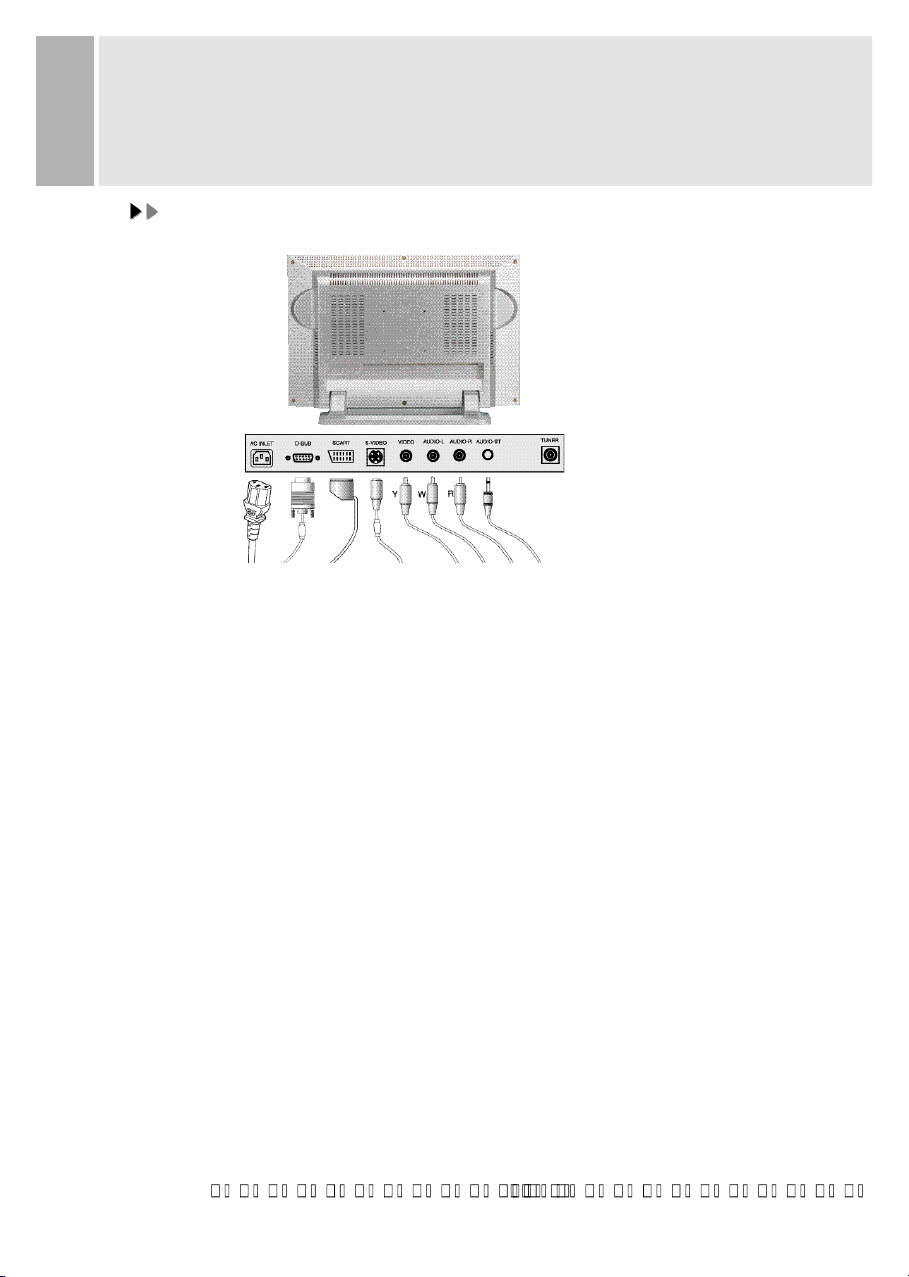
CONNECTING WITH EXTERNAL
EQUIPMENT
CCAAUUTTIIOON
N
Be sure to turn off the power of your computer before connecting the monitor.
1. CONNECT THE VIDEO SIGNAL CABLE
A. Connect one end of the signal cable to the back panel of the monitor
and connect the other end to the graphic card on back of the computer.
B. Secure the connection with the screws on the plug.
2. CONNECT THE POWER CORD
Connect the female end of the power cord to the power input
receptacle on the LCD Monitor.
Then, plug the male end of the power cord to an AC outlet or computer.
3. CONNECT THE A/V CABLE
A. Connect the end of RCA(Yellow, White, Red) SCART or S-VHS cable to
the terminals on the back of the Monitor.
B. Connect an antenna or CATV cable to the terminal on the back of the Monitor.
(Optional TV Tuner can be purchased from the dealer)
C. Connect one end of stereo audio cable to the stereo jack on the back of the Monitor.
(Connect another end of stereo audio cable to the “Audio(Line) out” terminal of
the sound card on your computer or another audio equipment)
D. Headphone may be connected to the headphone jack(option) on the left-hand side
of the Monitor.(While Headphone is connected, the sound from the built-in speaker
will be disabled)
4. TURN THIS MONITOR ON AND START YOUR SYSTEM
5. CONNECT THE TUNER(OPTION)
Page 7

Page 8
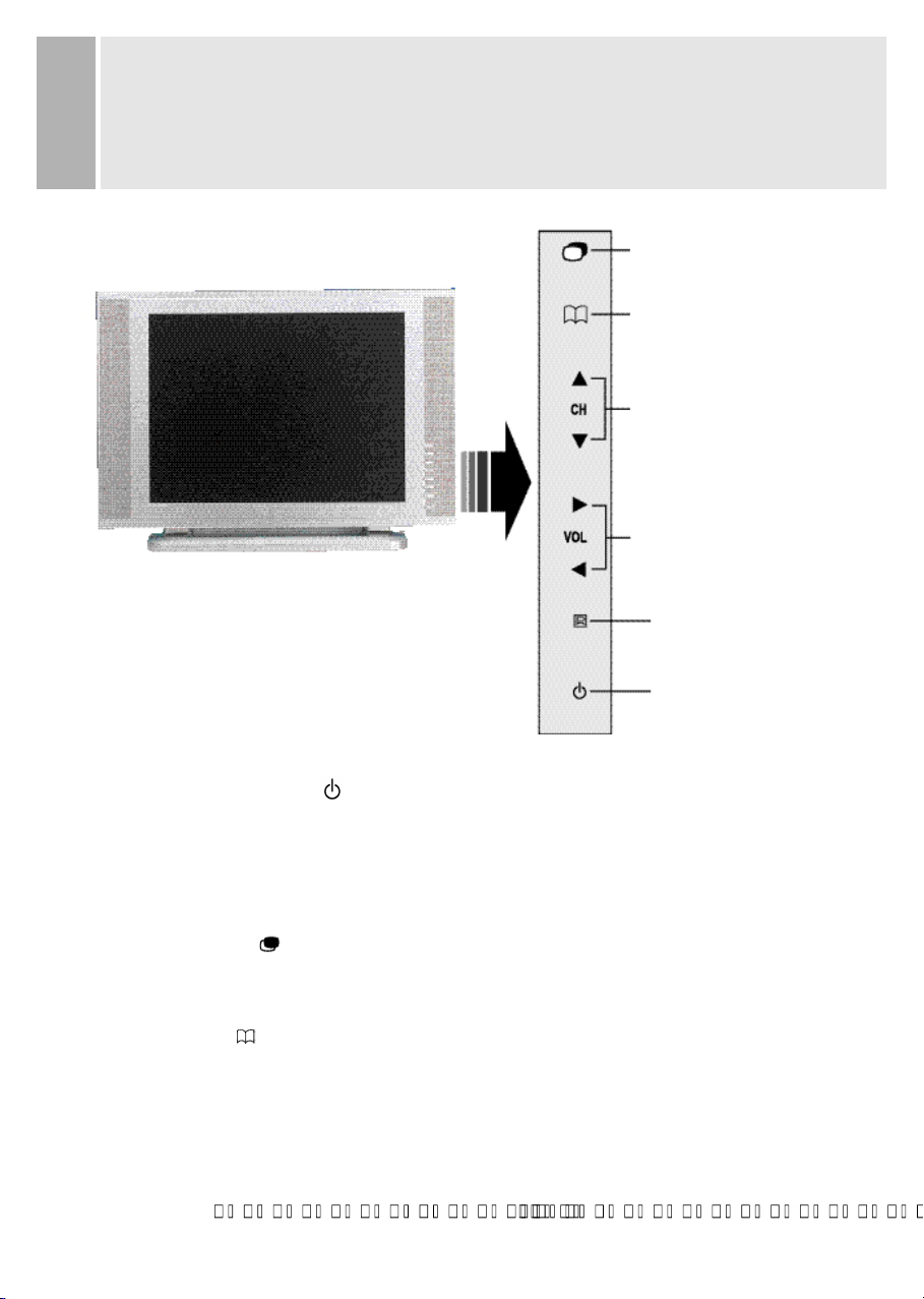
CONTROLS AND FUNCTIONS
B. SOURCE BUTTON
E. VOLUME BUTTONS
(LEFT & RIGHT)
D. CHANNEL BUTTONS
(DOWN & UP)
A. POWER SWITCH
A. POWER ON/OFF( )
Turns the power ON or OFF. There will be a few seconds delay before the
display appears.
The power LED(next to the power switch) lights with green when the power is turned ON.
The power is turned off by pressing the power switch again and the power
LED goes Red.
B. SOURCE ( )
Change input Source one by one
(PC, VIDEO, S-VIDEO, TV, SCART)
C. MENU ( )
Activates and exits the On Screen Display.
This button can also be used to move previous menu or status.
OSD MENU(MAIN) : Input Source, Screen, Audio, OSD, Color, Utility, Exit.
C. MENU BUTTON
REMOTE CONTROLLER
SENSOR
INSTRUCTION MANUAL 8
Page 9

CONTROLS AND FUNCTIONS
D. CHANNEL( CH: )
Increases or decreases the channel number.
(In PC mode, down key operates as “Auto adjust”)
This button allows user to enter the sub-menu of the activated function
when down key is pressed on the main menu.
E. VOLUME( VOL: )
Adjust the volume / Adjust menu settings.
1. SELF-TEST DISPLAY
When there is no connection at PC, the On Screen Display will show for 3 seconds.
Check input Signal
2. OSD MENU DESCRIPTION
: Input Source
Select PC or AV(TV, Video, S-Video, SCART) Source.
9 INSTRUCTION MANUAL
Page 10

CONTROLS AND FUNCTIONS
: Screen
: Brightness
Increase or decrease the intensity of the image.
: Contrast
Increase or decrease the intensity(lightness or dimness) of the image.
: H. position (PC Mode Only)
Move image horizontally on screen right or left.
: V. position (PC Mode Only)
Move image vertically on screen up or down.
: Clock (PC Mode Only)
Adjust the vertical noise of screen image.
: Phase (PC Mode Only)
Adjust the number of horizontal picture elements.
: Hue (AV, NTSC Only)
Adjust the tone of color.
: Saturation (AV Only)
Adjust the intensity of color level.
: Sharpness (AV Only)
Adjust the sharpness of video image.
INSTRUCTION MANUAL 10
Page 11

CONTROLS AND FUNCTIONS
: Audio
: Volume
Adjust audio volume.
: Equalizer (Loudspeaker Only)
Boost / Cut specific frequency or compensate for frequency
distortion of the sound
.
Select preferred Sound setting: flat, music, movie, speech and Adjust the
level of the Sound frequency in user mode.
: Balance (Loudspeaker Only)
Adjust the balance of left and right speaker sound
.
: Loudness (Loudspeaker Only)
Compensate the sound to consider the frequency sensitivity of human ear.
11 INSTRUCTION MANUAL
Page 12
CONTROLS AND FUNCTIONS
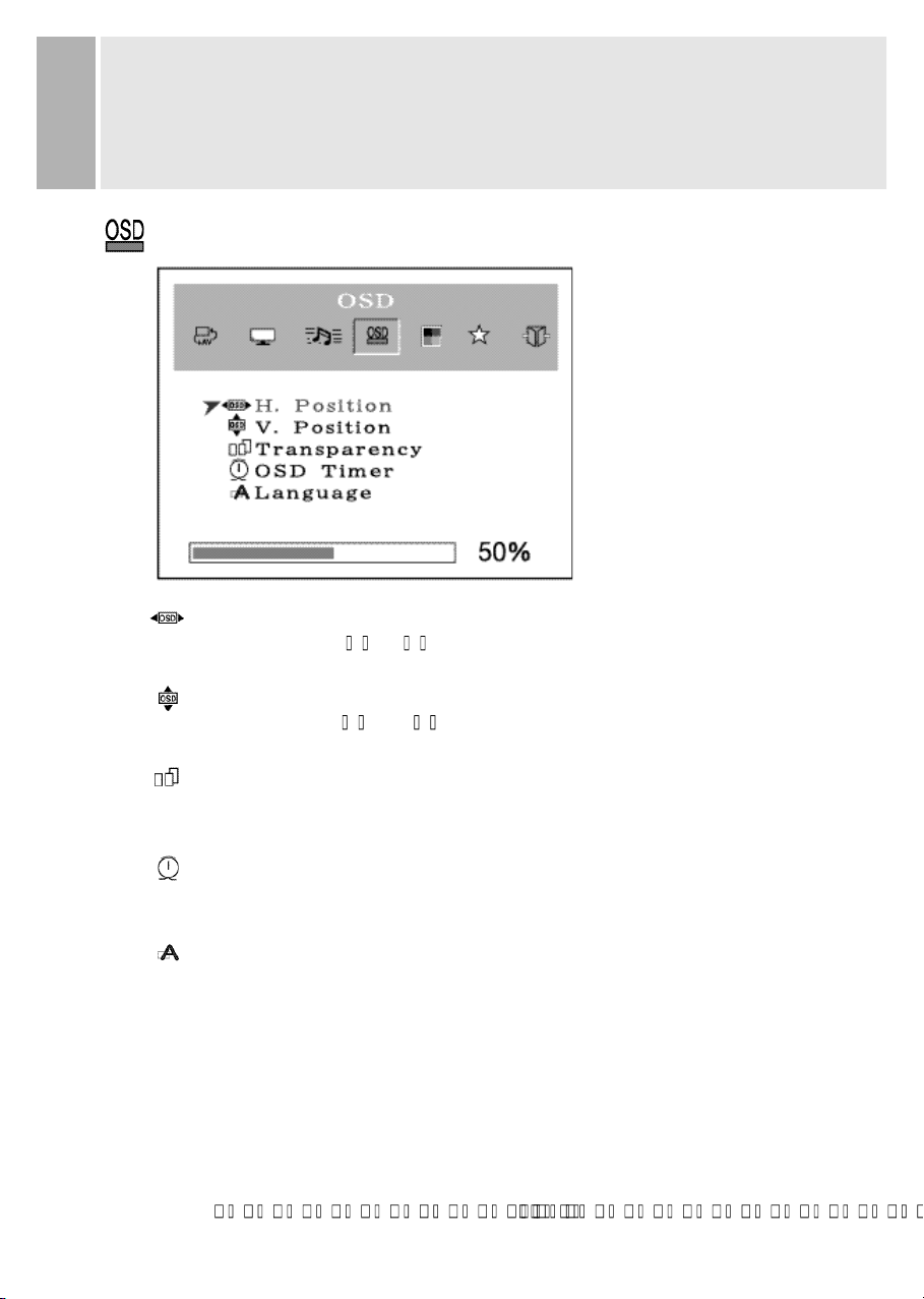
: OSD
: H. Position
Move the OSD position to right( ) or left( ).
: V. Position
Move the OSD position to up( ) or down( ).
: Transparency
Select the OSD background.
: OSD Timer
Select the OSD display timing.
: Language
Select a language among English, Français, Deutsch, Español,
Danish, Italiano.
INSTRUCTION MANUAL 12
Page 13

Page 14

CONTROLS AND FUNCTIONS
: Utility
: Recall
Select to reset all setting to the factory default values.
: Full Auto (PC Mode Only)
Auto geometry and color adjustment.
: Caption (NTSC Only)
Enable or disable closed caption feature(CC1, CC2, CC3, CC4).
: Vchip (NTSC, US Only)
Initial passwords is “0000”.
The V-chip can block certain rated television shows off
(if chosen) so children cannot watch programs that parents do not approve.
If the rating codes are higher than the preset values, the television signal
will be displayed.
To select V-chip on OSD, Enter 4 digits of number
if you Enter a wrong number, “Invalid number” will be displayed.
INSTRUCTION MANUAL 14
Page 15

CONTROLS AND FUNCTIONS
1) TV Guidelines
off : Not Rated
TV-Y : Young Children
TV-Y7 : Children 7 and over
TV-G : General Audience
TV-PG : Parent Guidance
TV-14 : Viewer 14 and over
TV-MA : Mature Audience
(FV : Fantasy Violence
V : Violence
S : Sexual Situation
L : Coarse Language
D : Suggestive Dialog)
2) MPAA Rating (Motion Picture Association of America
[Movie rating organization])
off : Not Rated
G : General Guidance
PG : Parental Guidance Suggested
PG-13 : Parents Strongly Cautioned
R : Restricted Under 17 Requires
NC-17 : No Children Under 17 Admitted
X : Adult only
3) New Password
Change Password Number.
15 INSTRUCTION MANUAL
Page 16

CONTROLS AND FUNCTIONS
: TV Channel (Program)
This menu is possible to select, Input Source must be set ‘TV’.
: Auto Search
Find available channels(Program) and save automatically.
: Fine Tuning
Adjust a mismatch between real and programmed channel(Program).
: Store / Clear
Select “Store” to save the channel(Program) or select “Clear” to
remove the channel(Program).
: TV Type (NTSC Only)
Select Air or Cable TV system.
: Channel(Program) Swap (PAL or SECAM Only)
Change current channel number to new channel number user want to
change(Channel number will be different with real channel number
after execute this menu).
: Region
Select a channel system that is being used in your region.
USA, Korea : NTSC(M) W.EU, Scand : PAL B/G
UK. Ireland : PAL I E.EU, CIS : SECAM D/K
M.East : SECAM B/G France : SECAM L/L’
INSTRUCTION MANUAL 16
Page 17

CONTROLS AND FUNCTIONS
: Exit
: Exit
Turn off OSD Menu.
17 INSTRUCTION MANUAL
Page 18

REMOTE CONTROLLER FUNCTIONS
1. POWER( )
Turns the power ON or OFF. There will be a few
seconds delay before the
display appears.
2. SOURCE
Select pc or video(TV / Video / S-Video / SCART)
sources.
3. MUTE
Mute the sound.
4. AUTOSCAN
Find available channels(programs).
5. MENU
Activates and exits the On Screen Display.
6. VOL( )
Increases or decreases the level of audio volume.
7. CH( )
Increases or decreases the channel number.
Up / Down the teletext page number in teletext mode
F. REMOTE CONTROLLER
INSTRUCTION MANUAL 18
Page 19

REMOTE FUNCTIONS
8. DISPLAY
Channel display in TV Source.
9. TV
Change Input Source to TV.
10. AUTO
Auto geometry adjustment in PC Source.
11. EXIT
Exit the On Screen Display.
12. TEXT ( )
Select Teletext display / Return to TV picture display.
13. INDEX ( )
Return to index page in teletext mode.
14. CANCEL( )
Display the TV picture on the screen while waiting for the new teletext page.
15. REVEAL( )
Reveal hidden text, such as Solutions of riddles or puzzles in teletext mode.
16. HOLD( )
Toggle hold on or off for current display page in teletext mode.
17. SIZE( )
Page expand in teletext mode.
18. SUBCODE( )
Select Sub page in teletext mode.
If Some page may be multiple in teletext, Select subcode Key and enter
four digits for the page you need.
19. (Multi-Channel TV Sound)
Access I/II Setting(Stereo, Mono, Second Audio Selection) when a TV signal is received.
20. RED / GREEN / YELLOW / CYAN
Change to associated page in the display block according to the acquisition mode
while teletext operating.
21. 0, 1, 2, 3, . . . 9(Number Key)
Using the 0, 1, 2, 3, . . . 9 Keys, the required channel or Teletext page are selected.
Teletext, I/II function is optional.
*
The teletext functions only work in TV and Video.
19 INSTRUCTION MANUAL
Page 20

G. AC INLET
Power cord connection.
NOTE:
Power cord is used as main power disconnect device in this product.
H. D-SUB CONNECTOR
Connect to the video signal cable.
ACCESSORY
1. POWER CORD
2. REMOTE CONTROLLER
3. USER’S MANUAL
4. A/V CABLES(Option)
5. Batteries (TYPE AAAX2)
REAR VIEW
G. AC INLET
H. D-SUB CONNECTOR
INSTRUCTION MANUAL 20
Page 21

STAND SLOPE
TORQUE BY POSITION
Recommend that the slope from 0 to 20 degree.
In case of the degree is more than 20, please refer below sheet.
SLOPEFOLD POSITION
A
B
C
21 INSTRUCTION MANUAL
-3 ~20
20 ~80
80 ~95
TORQUE(kgf cm)
23~27
78~85
23~27
Page 22

Page 23

MODE
ON
STANDBY
SUSPEND
ACTIVE OFF
UNSUPPORTED
MODE
POWER OFF
LED COLOR MONITOR OPERATION
Normal Operation
Screen blanks after preset idle time
and some electronic circuits or all
circuitry in the monitor shut down.
Normal operation but the on screen
display will show error massage.
Not opreation
< 50W
< 5W
< 5W
< 5W
MODE
ON
STANDBY
SUSPEND
ACTIVE OFF
POWER CONSUMPTION
POWER MANAGEMENT
This monitor features a power management system to “power down” upon receipt of the
VESA DPMS(The display power management signaling) from a VESA DPMS video card.
The VESA DPMS-compliant video card performs this signaling system through not
sending horizontal, vertical, or sync signal.
This monitor enters an appropriate mode through identifying each of the three modes
of the signaling system.
POWER CONSUMPTION
LED INDICATOR
The power management feature of the monitor is comprised of four
stages : On(Green), Standby, Suspend, Active off(Amber)
and Unsupported mode(Green).
GREEN
AMBER
GREEN
RED
23 INSTRUCTION MANUAL
Page 24

SPECIFICATIONS
LCD Type
20.1 Diagonal AM-TFT(Active-Matrix)
Pixel pitch(mm) : 0.51(H) 0.51(V)
BRIGHTNESS: 500cd/ (Typical)
CONTRAST RATIO: 500:1(Typical)
RESPONSE TIME: Tr -5msec, Tf-11msec(Typical)
RESOLUTION(H x V)
800X600 @75Hz
FREQUENCY
HORIZONTAL: 31-48KHz
VERTICAL: 56-75Hz
INPUT SIGNAL
VIDEO(Analog 0.7Vp-p / 75 )
SYNC(Separate TTL Level)
SCART, S-VIDEO, AV(Composite, Sound L/R)
PC Stereo Sound, RF(Tuner option)
ACTIVE DISPLAY AREA (W x H)
408mm X 306mm
DIMENSIONS (W x D x H)
583mm X 202mm X 429mm
WEIGHT
Net Weight : 8.7Kg
Gross Weight : 11.7Kg
ELECTRICAL RATINGS
AC100 - 240V, 50/60Hz (auto switching)
NOTE :
Technical specifications are subject to change without notice.
INSTRUCTION MANUAL 24
Page 25

1. Check that power cord of the Monitor have
been connected securely into wall outlet
or grounded extension cable or strip.
2. Power switch should be in the ON position
and LED is lit.
3. Check that the Brightness and/or the Contrast
adjustments of the Display have not been
turned down to minimum levels.
1. The signal cable should be completely
connected to the video card/computer.
2. The video card should be completely seated in
its slot and the computer is switched ON.
Push the down key in front side or
Auto key in remocon.
Adjust Clock and Phase in the OSD.
TROUBLESHOOTING GUIDE
25 INSTRUCTION MANUAL
TROUBLE TROUBLESHOOTING TIP
No image on display screen
“Check Input Signal”
message on screen
Display image is not
centered, too small or
too large in PC mode
Vertical or Horizontal noise
is present in the picture
 Loading...