

Orion Technology IC110HF011PT35, IC110HF011PT19, IC110HF011PT6.8, IC110HF011PT25, IC110HF012PT8.5 Operation Manual
...
Network
Camera
Operation Manual
Before reading this manual
This is a basic operation manual for use of a network camera. Users who are using this product for the first time, as
well as users with experience using comparable products, must read this operation manual carefully before use and
heed to the warnings and precautions contained herein while using the product. Safety warnings and precautions
contained in this operation manual are intended to promote proper use of the product and thereby prevent accidents
and property damage and must be followed at all times. Once you have read this operation manual, keep it at an easily
accessible location for future reference.
• The manufacturer will not be held responsible for any product damage resulting from the use of unauthorized parts and
accessories or from the user’s failure to comply with the instructions contained in this manual.
• The information in this document is believed to be accurate as of the date of publication even though explanation
about some functions may not be incorporated. The manufacturer is not responsible for any problems resulting from
the use thereof. The information contained herein is subject to change without notice. Revisions or new editions to this
publication may be issued to incorporate such changes.
• It is recommended that first-time users of this network camera and individuals who are not familiar with its use seek
technical assistance from their retailer regarding product installation and use.
• If you need to disassemble the product for functionality expansion or repair purposes, you must contact your retailer and
seek professional assistance.
• Both retailers and users should be aware that this product has been certified as being electromagnetically compatible for
commercial use. If you have sold or purchased this product unintentionally, please replace with a consumer version.
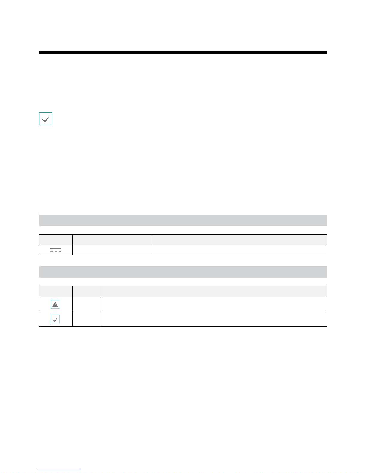
Safety Symbols
Symbol Publication Description
IEC60417, No.5031
Direct current
In-Text
Symbol
Type
Description
Caution
Important information concerning a specific function.
Note
Useful information concerning a specific function.
2

Before reading this manual
Safety Precautions
Important Safeguards
1. Read Instructions
All the safety and operating instructions should be read before the
appliance is operated.
2. Retain Instructions
The safety and operating instructions should be retained for future
reference.
3. Cleaning
Unplug this equipment from the wall outlet before cleaning it. Do not
use liquid aerosol cleaners. Use a damp soft cloth for cleaning.
4. Attachments
Never add any attachments and/or equipment without the approval
of the manufacturer as such additions may result in the risk of fire,
electric shock or other personal injury.
5. Water and/or Moisture
Do not use this equipment near water or in contact with water.
6. Placing and Accessories
Do not place this equipment on a wall or ceiling that is not strong
enough to sustain the camera. The equipment may fall, causing
serious injury to a child or adult, and serious damage to the
equipment. Wall or shelf mounting should follow the manufacturer's
instructions, and should use a mounting kit approved by the
manufacturer.
This equipment and cart combination should be moved with care.
Quick stops, excessive force, and uneven surfaces may cause the
equipment and cart combination to overturn.
Do not place this equipment in an enclosed space. Sufficient
ventilation is required to prevent an increase in ambient temperature
which can cause malfunction or the risk of fire.
7. Power Sources
This equipment should be operated only from the type of power
source indicated on the marking label. If you are not sure of the
type of power, please consult your equipment dealer or local power
company.
You may want to install a UPS (Uninterruptible Power Supply)
system for safe operation in order to prevent damage caused by
anunexpected power stoppage. Any questions concerning
UPS, consult your UPS retailer.
This equipment should be remain readily operable.
8. Power Cord
Operator or installer must remove power and TNT connections before
handling the equipment.
9. Lightning
For added protection for this equipment during a lightning storm,
or when it is left unattended and unused for long periods of time,
unplug it from the wall outlet and disconnect the antenna or cable
system. This will prevent damage to the equipment due to lightning
and power-line surges. If thunder or lightning is common where the
equipment is installed, use a surge protection device.
10. Overloading
Do not overload wall outlets and extension cords as this can result in
the risk of fire or electric shock.
11. Objects and Liquids
Never push objects of any kind through openings of this equipment
as they may touch dangerous voltage points or short out parts that
could result in a fire or electric shock. Never spill liquid of any kind on
the equipment.
12. Servicing
Do not attempt to service this equipment yourself. Refer all servicing
to qualified service personnel.
13. Damage requiring Service
Unplug this equipment from the wall outlet and refer servicing to
qualified service personnel under the following conditions:
A.
When the power-supply cord or the plug has been damaged.
B.
If liquid is spilled, or objects have hit the equipment.
C.
If the equipment has been exposed to rain or water.
D.
If the equipment does not operate normally by following the
operating instructions, adjust only those controls that are covered
by the operating instructions as an improper adjustment of other
controls may result in damage and will often require extensive work
by a qualified technician to restore the equipment to its normal
operation.
E.
If the equipment has been dropped, or the cabinet damaged.
F.
When the equipment exhibits a distinct change in performance —
this indicates a need for service.
14. Replacement Parts
When replacement parts are required, be sure the service technician
has used replacement parts specified by the manufacturer or that
have the same characteristics as the original part. Unauthorized
substitutions may result in fire, electric shock or other hazards.
15. Safety Check
Upon completion of any service or repairs to this equipment, ask the
service technician to perform safety checks to determine that the
equipment is in proper operating condition.
16. Field Installation
This installation should be made by a qualified service person and
should conform to all local codes.
17. Correct Batteries
Warning: Risk of explosion if battery is replaced by an incorrect type.
Replace only with the same or equivalent type.
Dispose of used batteries according to the instructions.
The battery shall not be exposed to excessive heat such as sunshine,
fire or the like.
18. Tmra
A manufacturer’s maximum recommended ambient temperature
(Tmra) for the equipment must be specified so that the customer and
installer may determine a suitable maximum operating environment
for the equipment.
WARNING: TO REDUCE THE RISK OF ELECTRIC SHOCK,
DO NOT REMOVE COVER (OR BACK).
NO USER-SERVICEABLE PARTS INSIDE.
REFER SERVICING TO QUALIFIED SERVICE
3

Before reading this manual
FCC Compliance Statement
THIS EQUIPMENT HAS BEEN TESTED AND FOUND TO COMPLY WITH THE LIMITS FOR A CLASS A DIGITAL DEVICE, PURSUANT TO PART
15 OF THE FCC RULES. THESE LIMITS ARE DESIGNED TO PROVIDE REASONABLE PROTECTION AGAINST HARMFUL INTERFERENCE
WHEN THE EQUIPMENT IS OPERATED IN A COMMERCIAL ENVIRONMENT. THIS EQUIPMENT GENERATES, USES, AND CAN RADIATE
RADIO FREQUENCY ENERGY AND IF NOT INSTALLED AND USED IN ACCORDANCE WITH THE INSTRUCTION MANUAL, MAY CAUSE
HARMFUL INTERFERENCE TO RADIO COMMUNICATIONS. OPERATION OF THIS EQUIPMENT IN A RESIDENTIAL AREA IS LIKELY TO
CAUSE HARMFUL INTERFERENCE, IN WHICH CASE USERS WILL BE REQUIRED TO CORRECT THE INTERFERENCE AT THEIR OWN
EXPENSE.
WARNING: CHANGES OR MODIFICATIONS NOT EXPRESSLY APPROVED BY THE PARTY RESPONSIBLE FOR COMPLIANCE COULD VOID
THE USER’S AUTHORITY TO OPERATE THE EQUIPMENT. THIS CLASS OF DIGITAL APPARATUS MEETS ALL REQUIREMENTS OF THE
CANADIAN INTERFERENCE CAUSING EQUIPMENT REGULATIONS.
WEEE (Waste Electrical & Electronic Equipment)
Correct Disposal of This Product
(Applicable in the European Union and other European countries with separate collection systems)
This marking shown on the product or its literature, indicates that it should not be disposed with other household
wastes at the end of its working life. To prevent possible harm to the environment or human health from
uncontrolled waste disposal, please separate this from other types of wastes and recycle it responsibly to promote
the sustainable reuse of material resources.
Household users should contact either the retailer where they purchased this product, or their local government
office, for details of where and how they can take this item for environmentally safe recycling.
Business users should contact their supplier and check the terms and conditions of the purchase contract. This
product should not be mixed with other commercial wastes for disposal.
This product contains software built partially on open-source content. Codes for the corresponding opensource content are available for download. For more information, refer to the software CD
(OpenSourceGuide\ OpenSourceGuide.pdf) or the open source guide accompanying this manual.
4

Table of Contents
Part 1 –Introduction& Remote Setup ........................................ 7
Introduction .................................................................................................................. 7
Quick Setup ........................................................................................................... 11
Remote Setup........................................................................................................ 12
Network ....................................................................................................................... 13
Video ........................................................................................................................... 14
Camera ....................................................................................................................................... 15
Streaming ................................................................................................................................... 15
Webcasting ................................................................................................................................ 15
MAT ................................................................................................................................................................................... 16
Privacy Masking ......................................................................................................................... 17
Audio ..................................................................................................................... 17
In/Out ......................................................................................................................................... 17
Event Action .......................................................................................................... 18
Alarm out .................................................................................................................................... 19
Email ........................................................................................................................................... 19
Remote Callback ......................................................................................................................... 20
Audio Alarm ............................................................................................................................... 20
FTP Upload ................................................................................................................................. 21
Event ........................................................................................................................... 23
Alarm In ...................................................................................................................................... 23
Motion Detection ....................................................................................................................... 24
1
5

Table of Contents
Trip-Zone ................................................................................................................................... 25
Audio Detection ........................................................................................................................ 26
Tampering.................................................................................................................................. 27
System Event .............................................................................................................................. 28
Part 2 – Web Viever ........................................................................... 29
Web Live Mode ..................................................................................................... 31
Web Play Mode ........................................................................................................... 33
Part 3 - Specification ........................................................................... 35
2
3
6

Part 1 - INTRODUCTION
In This Manual
This manual is intended for users of the network thermal camera and includes instructions for using and managing the
camera on the network.
Features
This network thermal camera compresses live video and transmits the video over Ethernet connections. The camera can be
accessed, configured and managed by using the PRO INIT (Integrated Network Installation Tool) program. It has a built-in
web server, Web Viewer, allowing you to monitor live video remotely using a web browser. The remote programs provided
with the camera also allow remote management, monitoring, searching and recording. This network thermal camera offers the
following features:
Thermal Night Vision Picture (Uncooled Micro bolometer Sensor)
Outstanding Detection Range (Max. 940m)
Display Specific Area Temperature (7.5~14 um)
H.265, H.264, M-JPEG compression algorithm
Various video compression resolutions
Two-way audio communication
Pre- and post-event buffering and video stream buffering to enhance reliability of network recording
Remote monitoring via web browser or remote software
Automatic HTML code generation for webcasting on a user’s website
Up to 10 simultaneous connections to the camera for remote monitoring
Enhanced security using IP address filtering, HTTPS, SSL and IEEE 802.1X functions and password protected multiple user
levels
Network bandwidth limit and MAT functions to use network bandwidth efficiently
Convenient network connection using the UPnP (Universal Plug and Play) function and built-in mDNS (Multicast DNS)
protocol
Supports ONVIF protocol
Convenient firmware upgrades via the network connection
Firmware duplication and autorecovery functions to enhance system stability
Management of multiple cameras via Ethernet connections
Event detection functions: Motion Detection,
Power sources: 12 VDC, PoE (Power over Ethernet)
NTSC or PAL programmable video output
IP66
NOTES:
In this manual, a “remote system” refers to a PC that the remote program (PRO CMS or Web Viewer) is running.
Remote monitoring and recording through multistream are available by using the PRO CMS program provided with the
camera.
7
Package Contents
Network Thermal Camera
Installation CD (PRO INIT/ PRO CMS software and User’s Manual)
Camera Sun Shield
Mounting Bracket and Screws
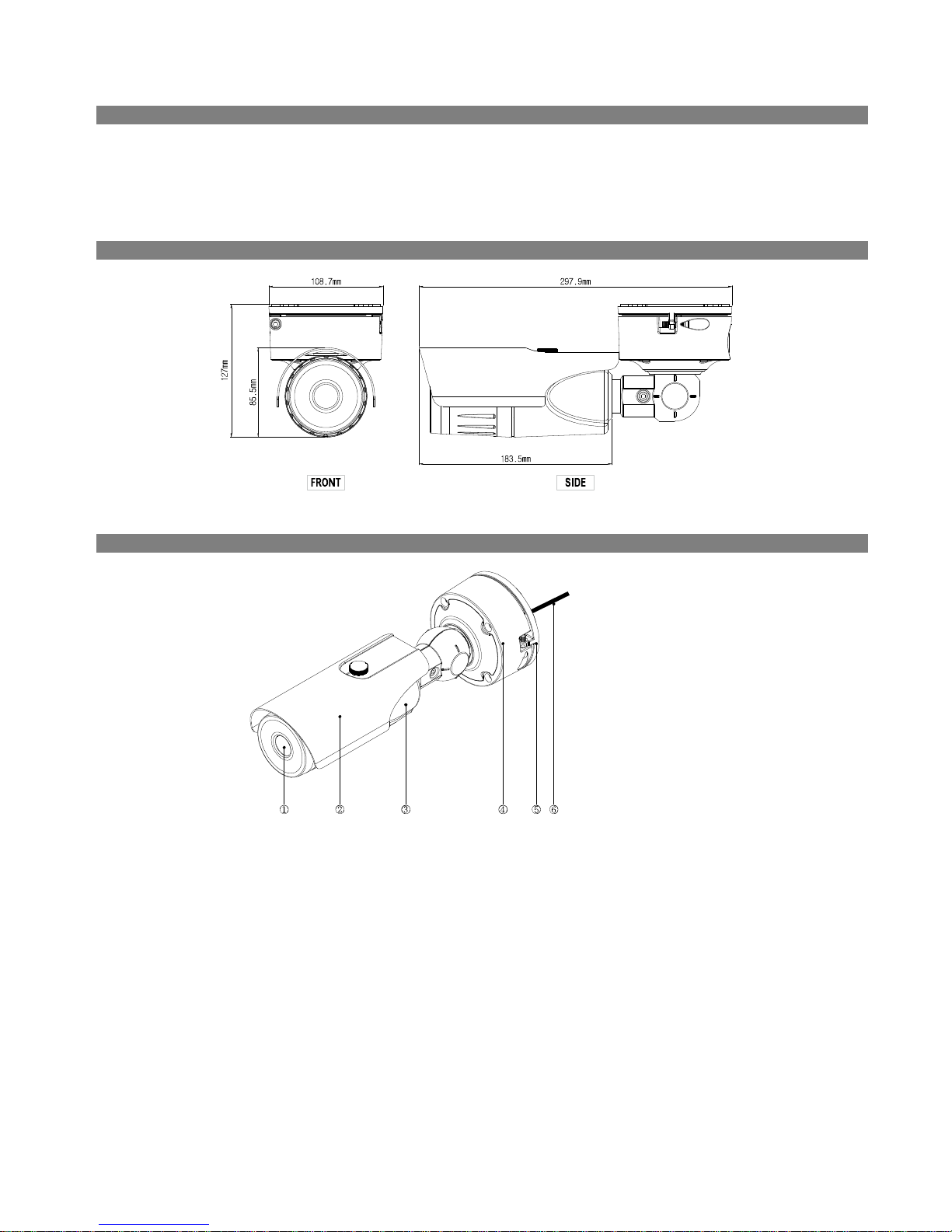
Dimensions
Illustrated Parts List
① Lens
② Sunshield
③ Body
④ Junction box
⑤ Mounting
Bracket
⑥ Cable
Lens: Thermal fixed lens installed.
Sunshield : Sunshield installed with screw.
Body : Body connected with camera stand.
Junction box: Allows user to arrange cable inside of it.
Mounting Bracket: Allows you to mount the camera to the wall or ceiling.
Cable Assembly: See below.
8
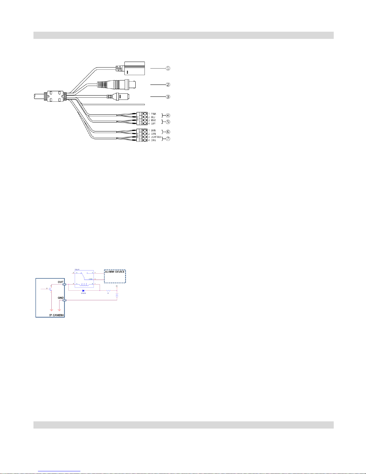
Cable Assembly
① Network Port
② BNC Video Out
(yellow cable)
③ Power In
(red cable)
④ Audio In
⑤ Audio Out
⑥ Alarm In
⑦ Alarm Out
Audio Out (black cable): Connect to an amplifier (Line-out). The camera does not have amplified audio output, so you
will need a speaker with an amplifier.
Audio In (white cable): Connect to an audio source (Line-in).
BNC Video Out (yellow cable): Connect to a monitor. This is intended for video preview while adjusting the camera.
Power In (red cable): Connect to the power adapter (12 VDC).
Network Port: Connect a Cat5 cable with an RJ-45 connector. You can change the settings, manage the camera, upgrade
the software or monitor video remotely via the network connection. Refer to the PRO INIT User’s Manual for details about
network connection setup. When using a PoE switch, the camera can be supplied with power over Ethernet cable (Refer to
the PoE switch manufacturer’s manual for details).
Alarm In: Connect an alarm-in device. Mechanical or electrical switches can be wired to the IN and GND (Ground)
connectors. The voltage range is from 0V to 5V. When the electrical switch is wired, the threshold voltage for NC (Normally
Closed) is above 4.3V and for NO (Normally Open) is below 0.3V, and it should be stable at least 0.5 seconds to be detected.
Alarm Out: It is the BJT (Bipolar Junction Transistor) - open collector output. If the voltage and current exceed the
specification limit (max. load: 50mA, max. voltage: 30VDC), the product could be damaged. When connecting the device
which exceeds the specification limit, refer to the picture (circuit) below.
CAUTION: If used with an external
inductive load (e.g. relay), a diode
must be connected in parallel with the
load for protection. Otherwise, the
product could be damaged.
NOTE: Camera surveillance may be prohibited by laws that vary by region. Check the laws in your area before using this
product for surveillance purposes.
CAUTIONS:
The camera restarts after the power adaptor is disconnected from the camera when switching the power source from
12 VDC to PoE.
The network connector is not designed to be connected directly with cable or wire intended for outdoor use.
WARNING: ROUTE POWER CORDS SO THAT THEY ARE NOT A TRIPPING HAZARD. MAKE CERTAIN THE POWER CORD WILL
NOT BE PINCHED OR ABRADED BY FURNITURE. DO NOT INSTALL POWER CORDS UNDER RUGS OR CARPET. USE THE
POWER CORD THAT HAS A GROUNDING PIN. IF YOUR POWER OUTLET DOES NOT HAVE A GROUNDING PIN RECEPTACLE,
DO NOT MODIFY THE PLUG. DO NOT OVERLOAD THE CIRCUIT BY PLUGGING TOO MANY DEVICES INTO ONE CIRCUIT.
Factory Reset
This will only be used on the rare occasions that you want to return all the settings to the original factory settings. Refer to
the PRO INIT User’s Manual for details on remote factory resetting.
CAUTION: When performing a Factory Reset, you will lose any settings you have saved.
9
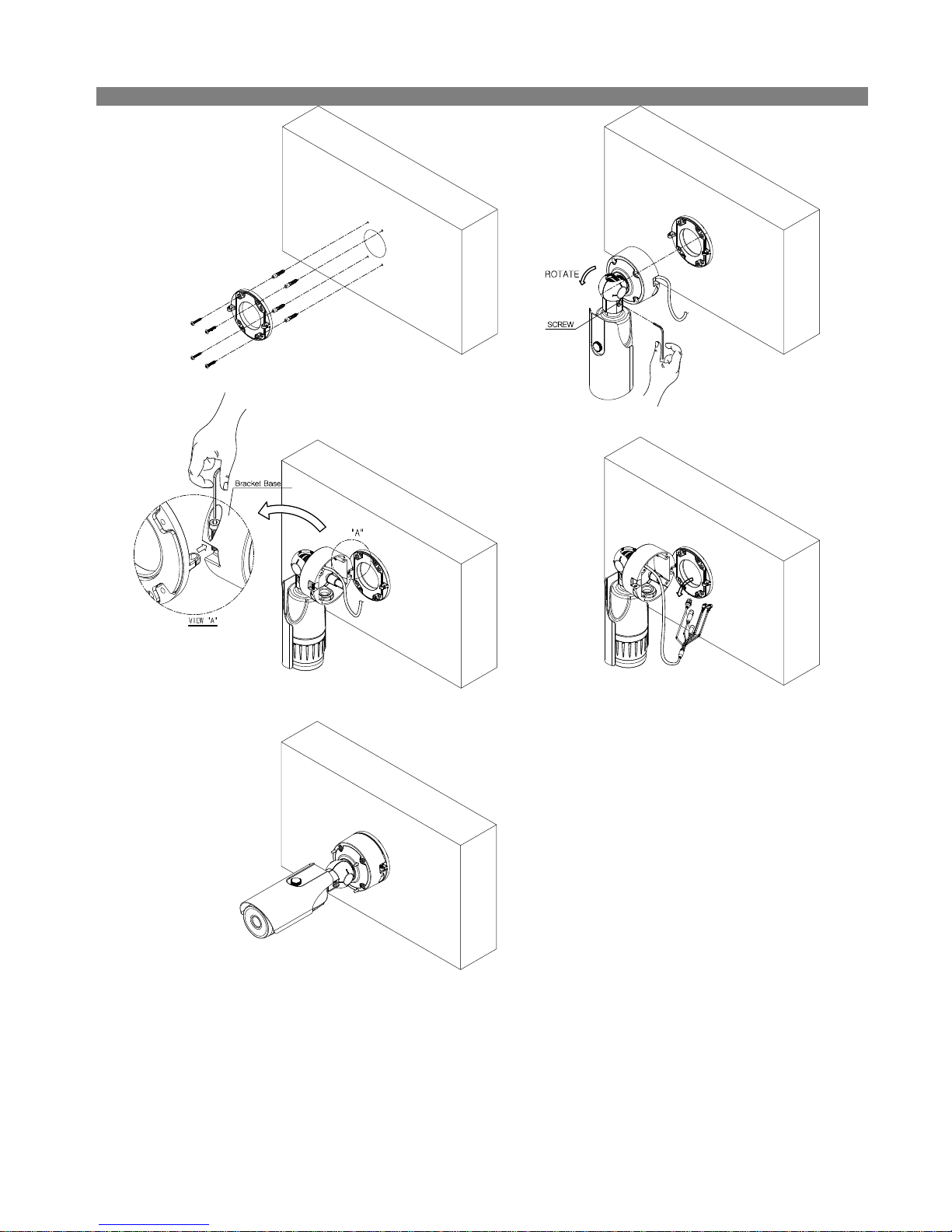
Installation
1. Please make the hole to the wall, and fix the base (mounting bracket) with screws.
2. Loosen the screws from stand bracket, and adjust camera body to 90 degree direction.
3. Adjust mounting bracket with camera junction box hole (View “A”) , and tighten the screw completely.
4. Please connect the cable.
5. Please tighten the screw from the junction box. And then adjust camera direction correctly and fix the bracket with screw.
WARNING: You might need to reinforce the wall or ceiling. If the wall or ceiling is not strong enough to support the camera,
the camera might fall damaging the camera or causing injuries.
①
② ③ ④
⑤
10
Part 1 - Remote Setup
Configure basic network camera settings and all other
system settings.
Screen images may vary depending on the model.
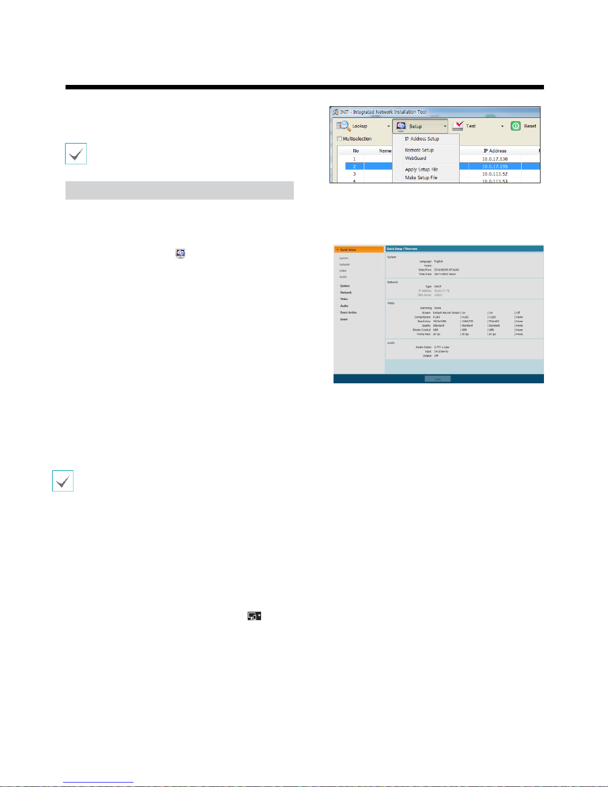
Remote Setup
1. Launch the PRO INIT program and then from the
main screen, select a network camera whose
settings you wish to change.
2.
Click on the
Setup
icon.
3. Select Remote Setup from the Setup menu to
load the Remote Setup screen. Alternatively,
you can select Network Camera from the main
screen and then right-click to access the
Remote Setup screen.
(Default setup for ID/Password = admin/admin)
From the Remote Setup screen, select the menu
on the left to display the current settings.
Select an option under the menu to change the
corresponding settings. Once you have changed
the settings, click
Save
to apply the settings.
• System settings can also be changed using a remote
program.
• Remote Setup works with the following web browsers
whenthe web browsers support HTML5: Microsoft
Internet Explorer version 10 or later, Google Chrome,
Mozilla Firefox, or Apple Safari.
It may not work properly with Microsoft Internet
Explorer version 9.0 or earlier.
It is recommended that you update the web browser
to the latest version. When you launch
Remote Setup
on a Microsoft Internet Explorer version 10 or
later supporting HTML5 and the
Remote Setup
screen
does not appear, check if the web browser’s document
mode is set to 9 or higher or
Edge
. You can check the
document mode as follows: Press the
F12
key on the
keyboard → click the
Document mode
icon.
11
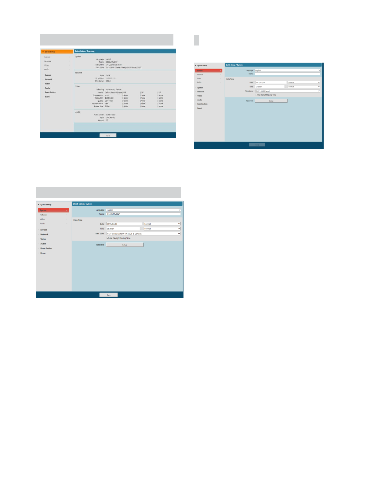
Quick Setup
General
Quick Setup allows you to set up
System, Network
,
Video, Audio
, and other basic settings needed for
camera use.
System
Change the camera’s system information, add users/
groups, and/or import/export settings.
•
Language
: Select the language you wish
to use for
remote setup.
• Name: Enter a name for the camera. (Up to 31
alphanumeric characters, including space).
• Date/Time
: Change the camera’s date/time settings
and display formats and configure the time zone and
daylight saving time settings. Click
Save
to apply the
changes right away.
12

Network
Change the network settings, enable DDNS and security
features, and control network bandwidth use.
• Type: Select the type of network you are using. If this
option has been changed, click Save to apply the
current settings, and then restart Remote Setup. If you
do not restart Remote Setup, the changes afterwards
will not be applied.
- Manual: Select if using a static IP. You will then be
able to configure the related settings manually.
-
DHCP
: Select if connected to the network using
DHCP. Click
Save
to retrieve IP address and other
network settings automatically from the DHCP
server.
• DNS Server: Enter the DNS server’s IP address. By
using the DNS server, you will be able to use domain
names instead of IP addresses when configuring the
DDNS, time, or SMTP server. If the camera is
connected to the network via DHCP, select the From
DHCP option to retrieve the DNS server’s IP address
from the DHCP server automatically. The updated
address will be displayed upon the subsequent
connection.
• Contact your network administrator for more
information on the camera's network connection
type, the DNS server's IP address, and other related
information.
•
If the camera is configured for a DHCP or ADSL network, it
is best to use the DDNS function because the camera IP
address might change frequently
13

Video
Configure
Camera, Streaming, Webcasting, MAT
,
And
Privacy Masking
options.
Camera
Image Sensor
Configure
Image Sensor
settings.
• Mirroring: Select Horizontal Reverse or Vertical
Reverse to flip the image horizontally or vertically.
- AGC : Select Auto Gain Control ON/OFF
> As applying the PlateauHistogram system used by
FLIR, it reduces the noise by using equalizing the imag
e data accumulated in the specific value by discarding
the value exceeding the threshold value in the existing
Histogram Equalization system.
> Default value is On. If it is set to Off, the image
color will change suddenly according to temperature
change, so it recommands to be set to On.
> If threshold value is set to higher, it becomes insens
itive to the temperature change, but the noise increa
ses.
- Threshold : Select AGC degree by adjusting the
bar.
Image Color
• Color Mapping LUT :
- Select one of color mapping type from total 8 types
• Color Display mode :
- This mode is used to fix the color value corresponding t
o the temperature at the moment of changing from Auto
Mode to Freeze Mode. it is used to prevent the color fro
m changing for the same object, due to the temperature c
hange during the exhibition or demonstration.
- Caution) If the background temperature is changed by mo
ving the position of the camera, please be sure to change
to Auto Mode and then change to Freeze Mode
• Display color bar :
- It shows the color bar for the Color Mapping LUT set b
y a user in the image
- Default is Off, so please set it to On when demonstrat
ed.

Miscellaneous
Configure
miscellaneous
settings.
• Color Mapping LUT :
- User can select Color table according to the environt
ment.
- Defulat setup is Anti-Iron, and other many uses are
WhiteHot and Rainbow. (Iron seems to have the best
resolution)
• Display Temperature for Center Point [ON/OFF]:
User can display temperature for center point as
below.
14

Streaming
• Primary/Secondary
> Multi stream is supported(Priority>Secondary).
Enable/disable streaming use.
The lower steam setting may change depending on
higher stream settings.
Webcasting
Use the webcasting service to view live images from the
camera on a web site.
HTML Code
: Copy and paste the html code shown on the
screen within the code of the web page you want the video
to be displayed.
Stream: Choose a stream to use for webcasting.
Only a stream currently in use can be selected.
**In order to use the webcasting service,
the
Allow
Anonymous Login
option under
System > User/ Group
must be selected
.
15

MAT
Select the
MAT
option to use the MAT (Motion Adaptive
Transmission) feature during video transmission and
recording.
• Frame Rate
: Designate the frame rate to be used
between the end of the Inactivity Period and the next
motion detection. When the slow shutter mode is
enabled under Video > Camera menu, the fame rate
may change. Video is transmitted and recorded at
the designated frame rate between then end of the
Inactivity Period and the next motion detection. Once
motion is detected again, the frame rate designated
under Streaming is restored immediately
MAT (Motion Adaptive Transmission)
is a feature
that lowers the frame rate when motion is not
detected to reduce the load on the network and save
on storage space. Based on the specified sensitivity
setting, no movement will be assumed if there is no
change between two consecutive images.
• Sensitivity
: Set the motion detection sensitivity.
Higher values will result in more sensitive motion
detection.
• Inactivity Period: Set the Inactivity Period. If motion
is not detected for the duration of time specified,
video is transmitted and recorded using the frame
rate designated below until movement is detected
again.
16

Privacy Masking
Select
Privacy Masking
to set up a privacy mask over
a specific area. The section on which a privacy mask is
applied will appear as black when monitoring video.
Audio
Configure audio in/out settings.
• Privacy Masking Setup
: Set up privacy masks. (Up
to 8)
-
(S
elec
t)/
(Unselect)
: Set or remove
a privacy mask. Click on the button and drag &
drop using the mouse to set up a privacy mask.
-
No./Name
: Displays a list of active privacy masks.
The numbers indicate privacy mask numbers. Select
the empty space next to a number to assign a name
to the corresponding privacy mask. Click
Delete
to
remove the selected privacy mask..
17

In/Output
•
Audio Codec
: Select an audio codec.
•
Input
: Select an option and then adjust the
volume.
•
Output
: Select an option and then adjust
the volume.
Cameras do not feature built-in audio amplifier
units and therefore require the user to purchase
a speaker system with a built-in amplifier
separately
Event Action
Designate event detection alert actions.
18

Alarm out
Select
Alarm Out
to enable alarm out.
Email
Select Email to send out emails.
• Dwell Time
: Designate the alarm out duration. When
an event occurs, alarm out will be generated for the
specified duration.
• Schedule
: Specify the alarm out schedule. Alarm out
is generated during the specified period only.
• SMTP Server/Port: Enter the SMTP server’s IP address
(or domain name) and port number you received
from the network administrator. If a DNS server has
been set up during network configuration, you can
enter a domain name instead of an IP address.
• Use SSL/STARTTLS
: If using an SMTP server requiring
an SSL or STARTTLS connection, select
SSL
or
STARTTLS
option.
• Authentication
: Enter a user ID and password if user
authentication is required by the SMTP server.
• Sender/Recipient(s)
: Enter the sender and recipients’
addresses. (Up to 10) The addresses must be properly
formatted and include the @ symbol.
19

Remote Callback
Select
Remote Callback
to send callback messages to a
remote system.
Audio Alarm
Select
Audio Alarm
to generate audio.
• Not supported from the Web Viewer program.
•
The camera must be registered to the remote
system in order to use the
Remote Callback
feature.
• IP Address: Enter the IP address and port number of
the remote system that will receive the messages.
• Retry: Designate how many reattempts to make if
message delivery fails.
•
List: Displays a list of audio files to playback. Click
Add or Remove to add/remove audio (.wav) files.
(supports 16-bit, 16KHz encoded files only) Select an
audio file from the list and then click Play to listen to
the file.
20

FTP Upload
Select
FTP Upload
to upload .jpg image of the event
detected to an FTP server.
• FTP Server: Click Add to register a new FTP server.
Click Remove to remove a registered FTP server.
When an event is detected, a .jpg image of the event
detected image is uploaded to the Primary Server.
If the upload to the Primary Server fails, the file will
be uploaded to the Secondary Server. Upload to the
Secondary Server will continue to be attempted until
successful. Fill out the fields below and click Test to
test the FTP server connection settings. Once the test
is complete, click OK.
-
FTP Server
: Enter the FTP server’s IP address (or
domain name).
-
Upload Path
: Designate the file upload path.
- Port: Enter the FTP server’s port number.
-
User ID, Password
: Enter the user ID and password
needed for connecting to the FTP server.
• Settings
: Configure image and upload settings.
-
Upload Type
: Choose an upload type. Select
Always
to upload images using the settings below,
irrespective of event detection. Select
Event
to
upload images using the settings below when an
event is detected.
-
Upload Frequency
: Activated only when Upload
Type has been set to
Always
. Designate the upload
speed. The specified number of images will be
uploaded to the FTP server during the specified
period of time.
-
Upload 1 image per
: Activated only when Upload
Type has been set to
Event
. Designate the upload
speed. Select
Upload
for and specify a duration.
Images will be uploaded for the specified duration
at the specified upload speed. Select
Upload while
event status is active
to upload images at the
specified speed only while event status is active.
21

-
Resolution/Quality
: Choose the resolution and
quality of the images to upload to the FTP server.
Range of resolution settings you can use here can
vary depe nding on the resolution setting applied
under
Video > Streaming.
-
Base File Name
: Enter a name for the files to be
uploaded to the FTP server and then choose file
identification options. Select
Add Date/Time Suffix
to add event detection date and time information
to each image file. Select
Add Sequence Number
Suffix - max. Count
to number the image files
based on the order of event detection. Select
Overwrite
to overwrite the previous image with
the new image. Event type is automatically added
to the file names.
.
• When specifying the Upload Path or Base File
Name, you cannot use special characters such as \, /,
#, *,
|,
:, ", <, >, and ?.
• The resolution of FTP upload image can change
depending on the resolution setting applied under
Video > Streaming.
• Set speed settings for Upload Frequency and
Upload 1 image per options in consideration of the
FTP server's performance. FTP uploads can fail if the
configured speed is higher than what the FTP server
can handle.
22

Event
Configure event detection settings.
Alarm In
Select
Alarm In
to enable alarm in event. With alarm
in event enabled, alarm in detections by the alarm in
connector will be assumed as events.
• Title: Enter the alarm-in device’s name.
• Type: Select the alarm in type.
• Event Action
: Select an alarm in event alert action.
-
Day & Night Mode
: Select if you do not wish to
use the IR cut filter when an event is detected. IR
LED non-supported model only Select this option
to override the
Day & Night Mode
settings under
Video > Camera
. Select
B&W Mode
to enable
black and white mode when an event is detected.
Expiration of the detected event will disable B&W
Mode and restore
IR Cut Filter.
- Alarm Out: Select if you wish to generate an alarm
out.
-
Send Email:
Select if you wish to send an email.
Select the
Image Attachment
option to attach a
.jpg image of the event detected to the email.
• Remote Callback:
Select this option to send a
message to a remote system and then select which
system to send the message to.
• Not supported from the Web Viewer program.
• The camera must be registered to the remote
system in order to use the Remote Callback
feature.
-
Audio Alarm:
Select this option to generate an
audio alert and then choose an audio file (.wav).
-
FTP Upload
: Select this option if you wish to
upload images to the FTP server.
- Record: Select this option to record video.
Event Action
settings must be configured correctly in
order to perform event actions.
23

Motion Detection
Select
Motion Detection
to configure motion detection
event settings. With motion detection event enabled,
motion detections within the designated area will be
assumed as events.
•
Motion Ignoring Interval
: With Motion Ignoring
Interval configured, no event log or notification is
generated for motions detected during a period of
time following a motion detection event.
• Daytime
: Specify when daytime starts and ends. All
other times will be assumed as nighttime.
• Event Action
: Select a motion detection event alert
action.
- Alarm Out: Select if you wish to generate an alarm
out.
-
Send Email
: Select if you wish to send an email.
Select the
Image Attachment
option to attach a
.jpg image of the event detected to the email.
-
Remote Callback
: Select this option to send a
message to a remote system and then select which
system to send the message to.
• Sensitivity
: Select daytime and nighttime motion
detection sensitivity levels. Higher values will result in
more sensitive motion detection.
• Minimum Blocks for Detection
: Select minimum
blocks for daytime and nighttime motion detection.
Motion must take place over the selected number
of blocks in order for it to be considered as a motion
detection event.
• Motion Zone
: Click
Setup
and define the motion
zone using blocks.
-
(S
elec
t)/
(Unselect)
: Enable/disable
motion detection.
-
(Single Block)
: Select/unselect motion
detection blocks individually.
-
(Zone)
: Select/unselect multiple
motion
detection blocks.
- (All): Select/unselect all motion detection
blocks
• Not supported from the Web Viewer program.
• The camera must be registered to the remote
system in order to use the Remote Callback
feature.
-
Audio Alarm
: Select this option to generate an
audio alert and then choose an audio file (.wav).
-
FTP Upload
: Select this option if you wish to
upload images to the FTP server.
- Record: Select this option to record video.
Event Action
settings must be configured correctly
in order to perform event actions.
24

Trip-Zone
Select
Trip-Zone
to configure trip zone event settings.
With trip zone event enabled, motion detected inside/
outside the selected area will be assumed as an event.
Motion Ignoring Interval
: With Motion Ignoring
Interval configured, no event log or notification is
generated for motions detected during a period of
time following a motion detection event.
• Daytime
: Specify when daytime starts and ends. All
other times will be assumed as nighttime.
• Event Action
: Select a trip zone event alert action.
- Alarm Out: Select if you wish to generate an alarm
out.
-
Send Email
: Select if you wish to send an email.
Select the
Image Attachment
option to attach a
.jpg image of the event detected to the email.
-
Remote Callback
: Select this option to send a
message to a remote system and then select which
system to send the message to.
• Sensitivity
: Select daytime and nighttime motion
detection sensitivity levels. Higher values will result in
more sensitive motion detection.
• Trip-Zone
: Click
Setup
and define the trip zone using
blocks.
-
(S
elec
t)/
(Unselect): Enable/disable trip zone.
-
(Single Block)
: Select/unselect trip zone blocks
individually.
- (Zone): Select/unselect multiple trip zone blocks.
- (All): Select/unselect all trip zone blocks.
-
Trip Direction
: Define in which direction the
motion has to occur in order for it to be considered
as an event. Select
In
for movement occurring from
outside the trip zone in and
Out
for movement
occurring from inside the trip zone out.
• Not supported from the Web Viewer program.
• The camera must be registered to the remote
system in order to use the Remote Callback
feature.
-
Audio Alarm
: Select this option to generate an
audio alert and then choose an audio file (.wav).
-
FTP Upload
: Select this option if you wish to
upload images to the FTP server.
- Record: Select this option to record video.
Event Action
settings must be configured correctly
in order to perform event actions.
25

Audio Detection
Select
Audio Detection
to configure audio detection
event settings. With audio detection enabled, an audio
detection taking place during the specified activation
period will be assumed as an event.
•
Audio Ignore Interval
: With Audio Ignoring Time
configured, no event log or notification is generated
for audio detections taking place during a period of
time following an audio detection event.
• Event Action
: Select an audio detection event alert
action.
- Alarm Out: Select if you wish to generate an alarm
out.
-
Send Email
: Select if you wish to send an email.
Select the
Image Attachment
option to attach a
.jpg image of the event detected to the email.
-
Remote Callback
: Select this option to send a
message to a remote system and then select which
system to send the message to.
• Sensitivity
: Define the audio detection sensitivity.
Higher values will result in more sensitive detection.
• Activation Time
: Specify how long audio has to be
detected for it to be considered as an event. Audio
detections that do not last for the specified duration
of time will not be considered as events.
• Use Ignoring Time
: Define the event ignoring time.
Audio detections taking place during the defined
time range will not be assumed as events.
• Not supported from the Web Viewer program.
• The camera must be registered to the remote
system in order to use the Remote Callback
feature.
-
FTP Upload
: Select this option if you wish to
upload images to the FTP server.
- Record: Select this option to record video.
Event Action
settings must be configured correctly
in order to perform event actions.
26

Tampering
Select
Tampering
to configure tampering detection
event settings. With tampering detection event enabled,
a sudden change in the video, such as due to movement
of the camera or covering up of the lens, will be
assumed as an event.
• Event Action
: Select a tampering detection event
alert action.
- Alarm Out: Select if you wish to generate an alarm
out.
-
Send Email
: Select if you wish to send an email.
Select the
Image Attachment
option to attach a
.jpg image of the event detected to the email.
-
Remote Callback
: Select this option to send a
message to a remote system and then select which
system to send the message to.
• Not supported from the Web Viewer program.
• The camera must be registered to the remote
system in order to use the Remote Callback
feature.
• Sensitivity
: Define the tampering detection
sensitivity. Higher values will result in more sensitive
detection.
• Activation time
: Specify how long tampering has
to be detected for it to be considered as an event.
Tampering detections that do not last for the
specified duration of time will not be considered as
events.
• Use Ignoring Time
: Define the event ignoring time.
Tampering detections taking place during the defined
time range will not be assumed as events.
-
Audio Alarm
: Select this option to generate an
audio alert and then choose an audio file (.wav).
-
FTP Upload
: Select this option if you wish to
upload images to the FTP server.
- Record: Select this option to record video.
Event Action
settings must be configured correctly
in order to perform event actions.
27

System Event
Select
System Event
and configure system event
settings. With system event enabled, system status,
alarm in status, and disk status will be checked
periodically and corresponding alerts will be generated.
• Alarm In Bad:
Select to check the alarm in status and
then set up a schedule.
-
Send Email
: Select to send out an email if no
change is detected in the alarm in status.
- Remote Callback: Select this option to send a
message to a remote system when the SD card is
inserted/removed and then select which system to
send the message to.
• Disk In/Out: Select to check if the SD card has been
inserted/removed.
- Send Email: Select to send out an email when the
SD card is inserted/removed.
- Remote Callback: Select this option to send a
message to a remote system when the SD card is
inserted/removed and then select which system to
send the message to.
• System Alive: Select to check the system status and
then set up a schedule.
-
Send Email
: Select to send out an email when the
system comes on line.
-
Remote Callback
: Select this option to send a
message to a remote system when the system
comes on line and then select which system to send
the message to.
• Email
and
Remote Callback
settings under
Event
Action
must be configured correctly in order to
send out emails and messages.
• Remote Callback
is not supported on Web Viewer.
• The camera must be registered to the remote
system in order to use the Remote Callback
feature.
28

Temperature Event
Select
Temperature Event
and configure the event
settings. With system event enabled, user can
denigrate the area where user would like to check the
min. & max. temperature from the screen as below.
• Temperature value for detection
-
Select temperature value starts to be detected for
event (alarm) out.
• Percent value for detection
- Select percent of temperature value to be
detected for event (alarm) out.
- After push the button named temperature event,
you can see the pop up screen as below.
- Then please click button and select the square
area like as above, and then push OK button.
- After that, user can see
min. & max. temperature
from the screen as above.
29

Part 2 – Web Viewer
Web Viewer is a program that allows you to view and search video from remote locations over the Internet and can be
accessed on a Microsoft Internet Explorer.
System requirements for running Web Viewer are as follows:
• OS: Microsoft® Windows® XP (Service Pack 3), Microsoft® Windows® Vista (Service Pack 1), Microsoft® Windows® 7
(Home Premium, Professional, Ultimate), Microsoft® Windows® 8 (Pro, Enterprise)
• CPU: Intel Pentium III (Celeron) 600MHz or faster (Core 2 Duo E4600 recommended)
• RAM: 128MB or more (2GB recommended)
• VGA: 8MB or more (128MB recommended) (1024x768, 24bpp or higher)
• Internet Explorer: Version 6.0 or later 32-bit
1
Launch Internet Explorer and then enter the following information in the address bar.
– http://IP Address:Port Number (Web Viewer connection port number selected during camera IP address and port
number setup)
– Or http://DDNS Server Address/DDNS name (DDNS Server address and DDNS name registered to the DDNS
Server)
• If the Use HTTPS option has been selected during Web Viewer port number setup, enter https instead of http. If
prompted with a security certificate warning, select "Continue to this website (not recommended)." If the Web
Viewer login page fails to load, configure Internet Explorer's settings as follows:
– Tools → Internet Options → Security → Custom Level... → Medium-high (default) or Medium.
– Tools → Internet Options → Advanced → Security → Use TLS 1.0 (select)
• If connecting by entering an IP address and a port number, you can connect by entering just the IP address if
Web Viewer connection port number has been set to 80 (443 when entering https).
• Contact your network administrator for the IP address of the camera you wish to connect to the Web Viewer pot
number.
30

2
When prompted with the Web Viewer login window, select
LIVE-PORT
or
PLAY-PORT
as the desired mode.
Enter the ID and password and click
LOGIN
to sign in using the selected mode.
(Default setup for ID/Password = admin/admin)
• Web Viewer supports Microsoft Internet Explorer only and no other type of web browser.
• Web Viewer does not work with Microsoft® Windows
®
8 metro UI.
• Do not close the login window while Web Viewer is running. Switching over to Web Live or Web Search mode can
cause a script error, requiring you to restart the Web Viewer program.
• To use Web Viewer on Microsoft Windows Vista or above, launch Internet Explorer by right-clicking on the icon
and selecting the
Run as administrator
option. Otherwise, certain Web Viewer functions might not be available.
• When running Web Viewer, the bottom section of the screen may get cut off if the address bar or the status bar is
shown. In this case, change Internet Options so that the address bar or the status bar is hidden. (
Tools → Internet
Options → Security → Custom level... → Allow websites to open windows without address or status bars
(
Enable))
• Launching a new version of Web Viewer for the first time can cause Internet Explorer to load information from the
previous version. In this case, navigate to Tools → Internet Options → General, delete temporary Internet files, and
then restart Web Viewer.
• On Microsoft Windows Vista or above, lowered image transmission rate can prevent the screen from being displayed
or updated. In this case, we recommend that you disable the computer's auto tuning function. Open the command
prompt as an administrator. (
Start → Accessories → Command Prompt → Right-Click
and then select
Run as
administrator
) Type in "
netsh int tcp set global autotuninglevel=disable
"and then press Enter. Restart the
computer to apply the change. To enable auto tuning again, launch the command prompt as an administrator and
then type in "
netsh int tcp set global autotuninglevel=normal
". Restart the computer to apply the change.
31

Web Live Mode
A remote web monitoring program that allows you to monitor images from remote locales in real -time.
1
Information: You can see general information about camera
2
Play Viewer: Click This button, change to play viewer
3
Quad Picture: You can select quad picture, full screen picture
4
Export: Export Image file and remote mode.
5
Color: Adjust Camera Brightness, Contrast, Saturation, Hue of monitored Image, Also you can see revert
image by press revert button.
6
PTZ: Zoom in / out picture, Iris Control, Focus Control.
②
③
④
⑤
⑥
⑦
①
32

7
Alarm: On /Off Selectable
8
to control an alarm out device remotely (A and B type models only). Alarm-Out Control: Click
9
Event Status Window: The event status window at the bottom displays a list of events that were detected in the camera.
/
Alarm In On/Off
Motion Detection
Trip-Zone
Tamp
10
1. Screen Popup Menu: Clicking the right mouse button on the screen displays the screen popup menu.
− Change Camera Title: Select to change the camera title.
− Enable Audio: Select to enable audio communication with the
site which the camera is installed and the audio control
panel appears (A type model only). Click the button to send
audio to the site which the camera is installed and speak into the
microphone. Click the button to monitor live audio from
the site which the camera is installed through the attached
speaker. Clicking both the and buttons allows twoway communication. Clicking the button disables audio
communication.
− Aspect Ratio: Select to change the image aspect ratio displayed on the screen and the
option menu appears. Selecting Fit to Screen displays images by fitting them to the
screen size. Selecting Original Ratio displays images by fitting them to the screen size
while maintaining their original ratio. Selecting Half Size (x0.5) to Quadruple Size (x4)
displays the images at the selected image size.
− Multistream: Select to choose the desired stream if the camera is in multistream
mode.
− Anti-Aliasing Screen: Select to enhance image display quality by eliminating stair stepping
(aliasing) effects in the enlarged image.
• The image adjustment for the monitoring screen works only in the pause mode.
• A camera name change in the Web Watch mode does not affect the camera name set up on the camera. Leaving the
Camera Title blank causes the camera name set up on the camera to display.
• Aspect Ratio – Half Size (x0.5) to Aspect Ratio to Quadruple Size (x4) in the Screen Popup Menu will be enabled
when the selected camera screen can display images in those sizes.
33

Web Play Mode
A remote web search program that allows you to search for recordings from remote locales in real-time.
While in Web Search mode, connection to remote locales will terminate automatically after 30 minutes of inactivity.
1
Information: You can see general information about camera Play Viewer: Click This button, change to play viewer
.
2
Quad Picture: You can select quad picture, full screen picture
.
3
Export: Click clip to save any video clip of recorded data as a video file
.
Click image to save the current image in a bitmap or JPEG file format.
Click Print to print the current image on a printer connected to your computer.
4
Zoom: Adjust Zoom in /out
.
②
③
③
④
⑤
⑥
⑦
⑧
⑨
34

5
Brightness: Adjust Brightness
.
6
Image Filter: Click to blur, sharpen, equalize, revert and interpolate playback images.
NOTE: Image processing works only in the pause mode.
7
Time-Lapse Search: Click to enter the time-lapse search mode which allows you to search for recorded
data by time and then play back images found within the time parameters. The Timetable window
located at the bottom displays the time information for the image of the date selected on the calendar.
If the camera has more than one video segment in the same time range, you can select the video segment
you want to search. Clicking a specific time displays the image recorded at that time on the screen.
Selecting allows you to display an image from a specific time.
8
Event Search: Click to enter the event search mode which allows you to search for event log entries using specific conditions
and play back the images associated with those event entries.
9
Screen Popup Menu: Clicking the right mouse button on the screen displays the screen popup menu
- Change Camera Title: Select to change the camera title.
- Enable Audio: Plays audio while playing back recorded video that has recorded audio.
- Aspect Ratio: Changes the image aspect ratio.
- Anti-Aliasing Screen: Select to enhance image display quality by eliminating stair stepping (aliasing) effects in the
enlarged image
NOTE: A camera name change in the Web Search mode does not affect the camera name set up on the camera. Leaving the
Camera Title blank causes the camera name set up on the camera to display
35

Part 3 – Specification
36
 Loading...