

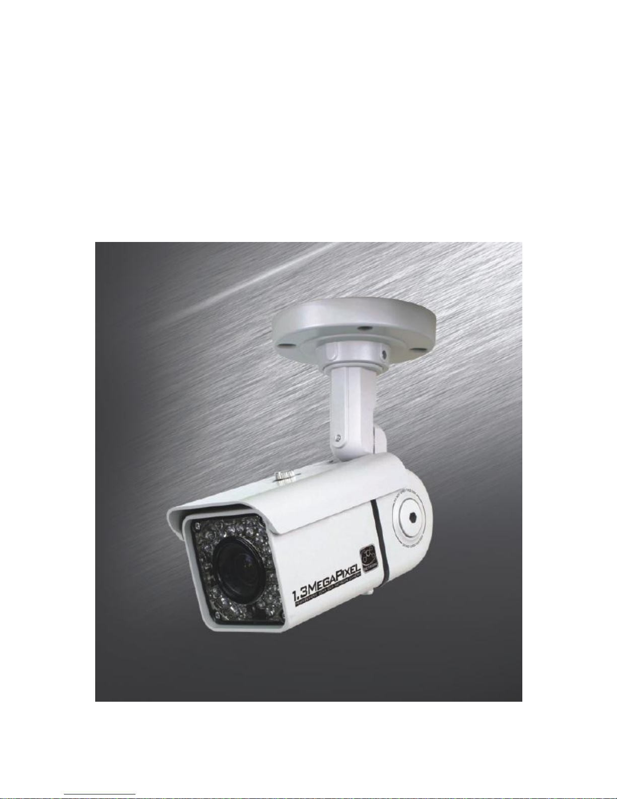
H.264 Mega-Pixel
NETWORK CAMERA
USER MANUAL
2

3
INDEX
Introduc tion ........................................................................................................................................... 6
Safety Cautions ..................................................................................................................................... 6
Chapter 1. Package .............................................................................................................................. 7
1.1 Came ra Features ...................................................................................................................... 7
1.2 Package .................................................................................................................................... 7
1.3 HOW TO INSTALL ................................................................................................................... 8
1.3.1 Accessories for installation ............................................................................................ 8
1.3.2 Configuration .................................................................................................................. 9
1.3.3 WAL L MOUNT ............................................................................................................. 10
1.3.4 CEILING MOUNT ......................................................................................................... 13
1.3.5 Foc us adjustment ......................................................................................................... 16
1.3.6 Control board ............................................................................................................... 17
1.4 Specification ........................................................................................................................... 18
1.4.1 Came ra Spec ification .................................................................................................... 18
1.4.2 Came ra Function .......................................................................................................... 18
1.4.3 Network Specification .................................................................................................. 19
1.4.4 Electric Spec ification ................................................................................................... 19
1.4.5 Alarm Input/Output ....................................................................................................... 20
1.4.6 Audio Input/Output ....................................................................................................... 20
Chapter 2. Installation and Video check ............................................................................................. 21
2.1 Ins tallatio n.............................................................................................................................. 21
2.2 Video check............................................................................................................................ 22
2.2.1 Change the s etting value of PC network environme nt ................................................. 22
2.2.2 Connec t the came ra with web brows er........................................................................ 23
2.2.3 See the video................................................................................................................ 24
2.2.4 Active-X auto installation ............................................................................................ 24
2.2.5 Installation complete .................................................................................................... 26
2.2.6 Net Viewer description ................................................................................................ 27
Chapter 3. Network Setting ................................................................................................................ 28
3.1 Check Network and Installation Type .................................................................................... 28
3.2 Installatio n without IP sharing device(router)......................................................................... 28
3.2.1 Static IP Setup .............................................................................................................. 28
3.2.2 Dynamic IP Se tup ......................................................................................................... 32
3.3 Installatio n with IP sharing device(router).............................................................................. 34
3.3.1 Gene ral Installation ...................................................................................................... 34
Chapter 4. Gene ral Information .......................................................................................................... 36
Chapter 5.System Information ............................................................................................................ 37
5.1 Came ra Name ......................................................................................................................... 37

4
5.2 Language ................................................................................................................................ 37
5.3 Administrator's ID and Password Change............................................................................... 38
5.4 Network Setting ..................................................................................................................... 38
5.5 Web port................................................................................................................................. 38
5.6 DDNS...................................................................................................................................... 39
5.7 Date & Time........................................................................................................................... 39
5.8 User Registration ................................................................................................................... 40
5.9 Firmware Upgrade.................................................................................................................. 41
5.10 System Reset/Restart ........................................................................................................... 41
Chapter 6. Stream Information ........................................................................................................... 42
6.1 Video ...................................................................................................................................... 42
6.2 Audio ...................................................................................................................................... 43
6.3 RTSP Setting .......................................................................................................................... 43
6.4 OSD ........................................................................................................................................ 44
6.5 Privacy Zone .......................................................................................................................... 45
6.6 External Video ....................................................................................................................... 45
6.7 HTTP/CGI .............................................................................................................................. 46
Chapter 7. Event Information ............................................................................................................. 47
7.1 Motion .................................................................................................................................... 47
7.2 Alarm Input............................................................................................................................. 47
7.3 Alarm Output .......................................................................................................................... 48
7.4 E-Mail .................................................................................................................................... 48
7.5 FTP ........................................................................................................................................ 49
Chapter 8. Came ra Information .......................................................................................................... 50
8.1 Day & Night ........................................................................................................................... 50
8.2 Color ...................................................................................................................................... 50
8.3 White Balance ........................................................................................................................ 51
8.4 WDR ....................................................................................................................................... 51
8.5 Digital Noise Reduction(DNR)................................................................................................. 52
8.6 Effect ..................................................................................................................................... 52
8.7 Sense Up ................................................................................................................................ 52
8.8 Shutter Speed ......................................................................................................................... 53
Chapter 9. IP Manager........................................................................................................................ 54
9.1 Use of IP Manager.................................................................................................................. 54
9.1.1 Run IP Manager program.............................................................................................. 54
9.1.2 Find IP address ............................................................................................................ 55
9.1.3 Change IP address........................................................................................................ 55
Chapter 10. Bas ic Ne twork ................................................................................................................ 59
10.1 Public IP ............................................................................................................................... 59
10.2 Private IP ............................................................................................................................. 60

5
10.3 Ping tes t ............................................................................................................................... 61
Chapter 11. Appendix ......................................................................................................................... 63
11.1 Bas ic setting table ................................................................................................................ 63
11.2. Troubleshooting of cable connection................................................................................... 64
11.3 Troub leshooting of network connection ............................................................................... 65
Chapter 12. Troubleshooting.............................................................................................................. 66
Chapter 13. Warranty Card ................................................................................................................ 67

6
Introduction
This is a megapixel network camera which uses a 1/3-inch megapixel progressive scan SONY CMOS
sensor.
Built-in H.264, MPEG 4, MPEG CODEC and streaming s erver, the advantage of this camera allow you
to monitor real time image from a remote location via internet. This camera s upports both static IP and
dynamic IP, and can change communication port, resulting in one IP address supporting mul tiple
servers. It also supports CMS(Central Monitoring Sys tem), various services and fea tures waterproof
for outdoor use without extra device.
<Cau tion>
So ftware, s erver and service may be charged according to change of policy or may be
stopped without prior notification. Appearance, function and specification may be changed
without prior notification. Our company assumes no responsibility for visible or invisible loss
resulted from changes in policy or products .
Safety Cautions
*This camera may be damaged by electrical and physical shock.
Use regulated 12V DC, 1A power supply. Do not throw or drop it on to floor.
*In case the unit fails, DO NOT try to disassemble the product.
Contact or consult the distribu tor or an authorized technician for a fter -sales service.
Warranty void for the product dis ass embled without an authorization from the distribu tor or
an authorized technician.
* All res ponsibility by us ing this unit is on the us er.
*In case it is ins talled at high loca tion, be sure to mount securely to prevent the unit from
falling below.
7
Chapter 1. Package
1.1 Camera Features
1) Firmware upgrading and function con trolling are available by network.
2) Built-in 1.3 Mega pixel 1/ 3" progress ive scan SONY CMOS s ens or.
3) Triple codec(H.264, Mpeg4, MJPEG )
4) This camera has a mechanical exchange of two filters with Sens e up function to
receive the maximum available ligh t a t nigh t.
5) Equipped wi th a number of con venient new functions such as OSD, Mo tion de tection , Privacy
ZONE and E-zoom.
6) Two-way audio support
7) This camera adopted PoE that supplies power in addition to data sending and receiving us ing
LAN cable withou t separate power connection and it provides convenience for users at
installation. When you connect the camer a with PoE and DC adap tor, Only PoE is used.
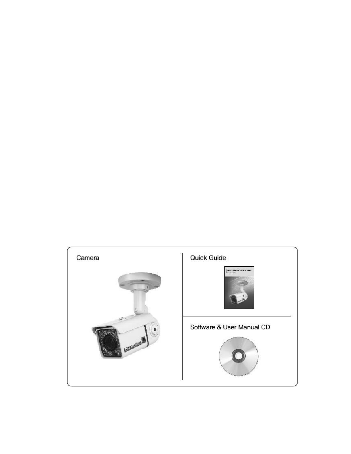
1.2 Package
Package of products is compos ed of camera , screw, user manual, software CD(see below).
Please check before starting installation. If there are any missing, please contact the shop where you
purchased.
[Caution] Please see the package as follows . This manual is based on Microsoft Windows XP. So, there
would be the difference according to operating system
8
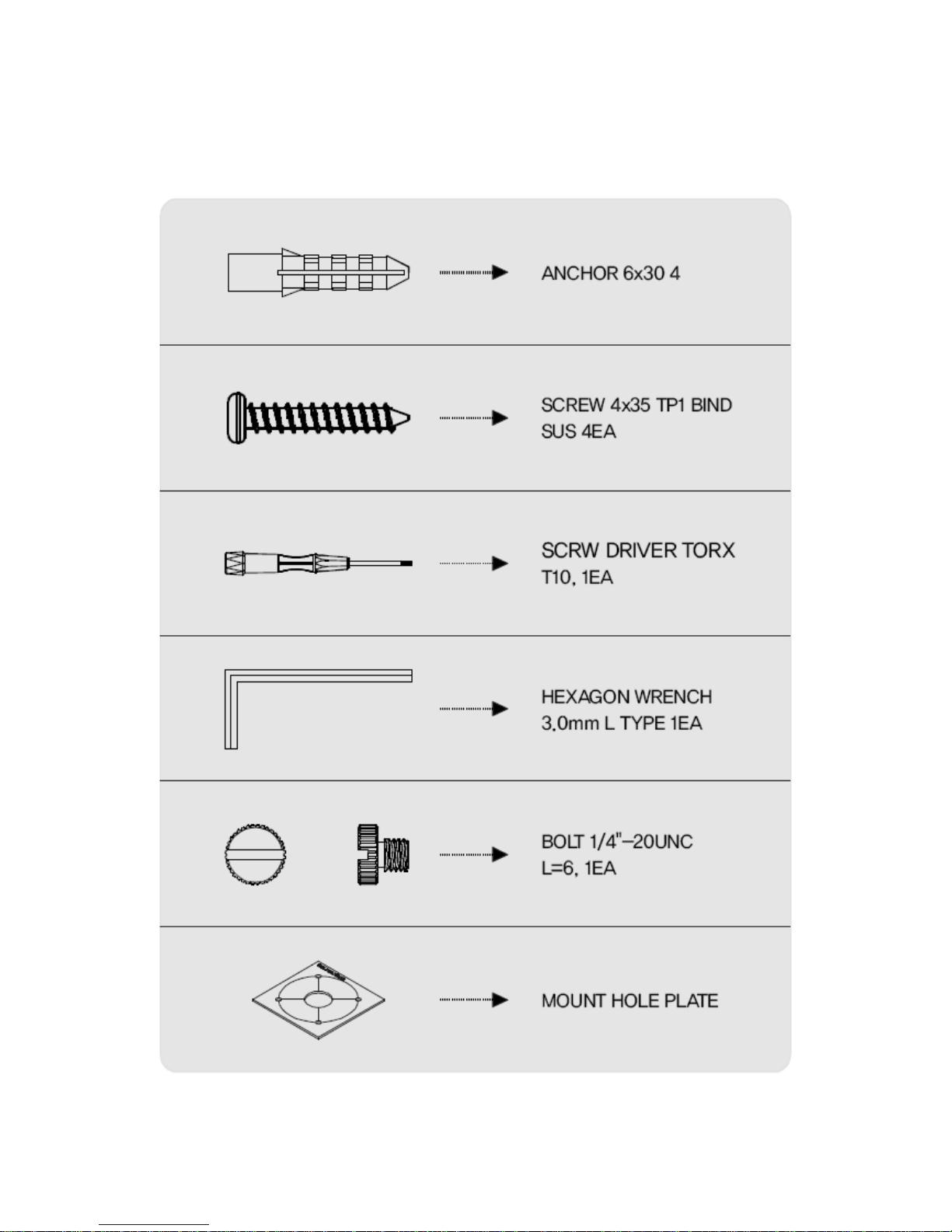
1.3 HOW TO INSTALL
1.3.1 Accessories for installation
9
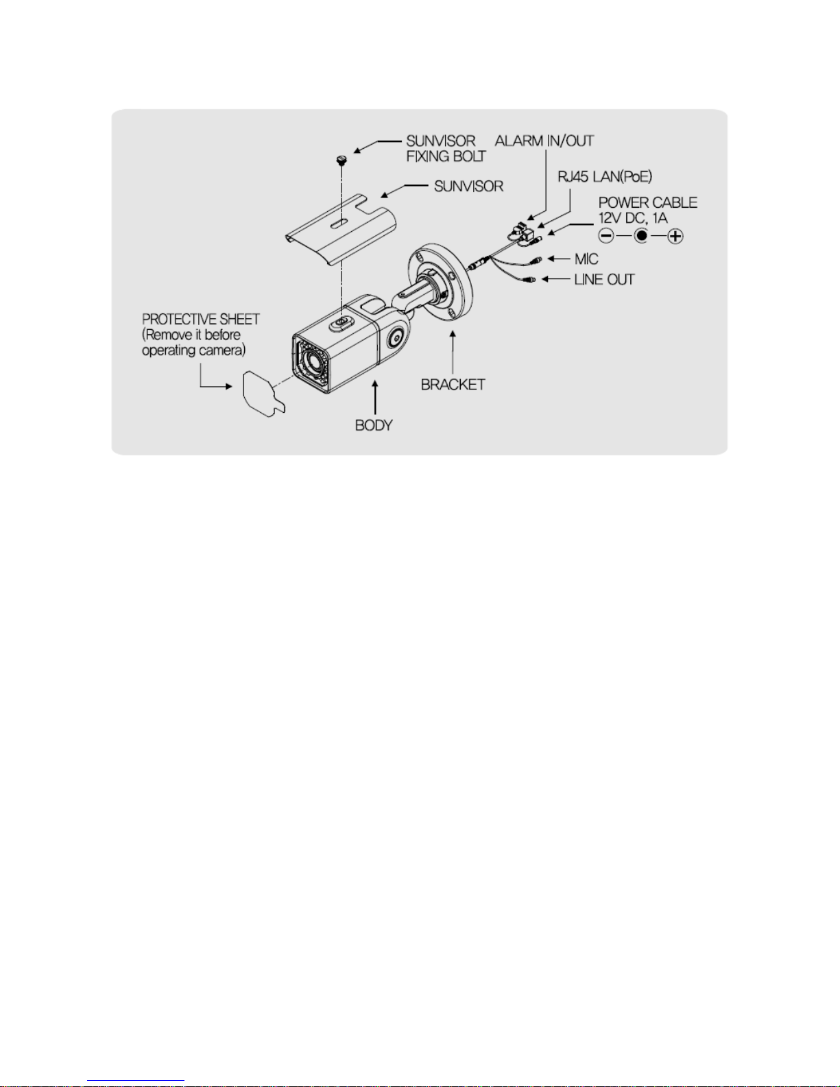
1.3.2 Con figuration
[Reference] Please refer to 1.4.5. regarding 'Alarm In/Out'
10
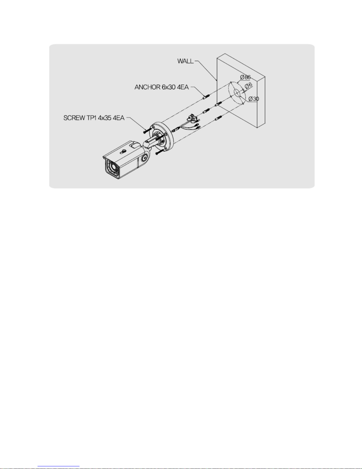
1.3.3 WALL MOUNT
1. Make a hole of 30mm in diameter for pass ing cable.
2. Using the mount hole pla te, drill four holes on the wall.
3. Insert the anchors.
4. Fix the screws.
11
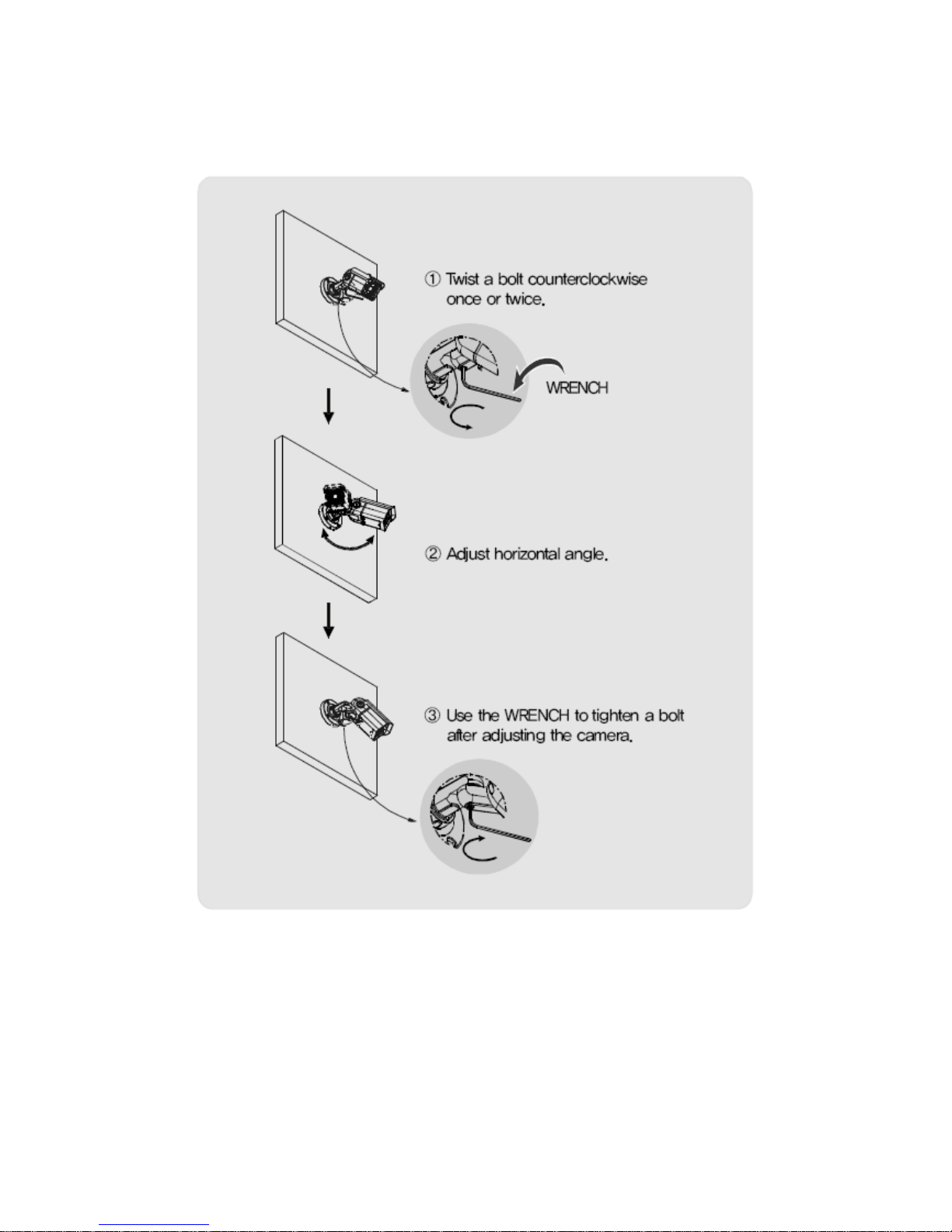
<Adjust horizontal angle>
1) Loos en a bolt to adjust horizontal angle of the camera.
2) Use the WRENCH to tigh ten a bolt a fter adjusting the camera.
12
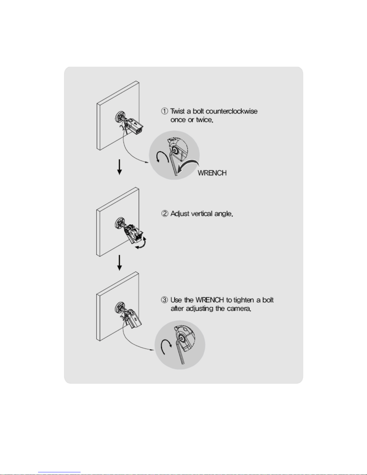
<Adjust vertical angle>
1) Loos en a bolt to adjust ver tical angle of the ca mera.
2) Use the WRENCH to tigh ten a bol t after adjus ting the camera.
13
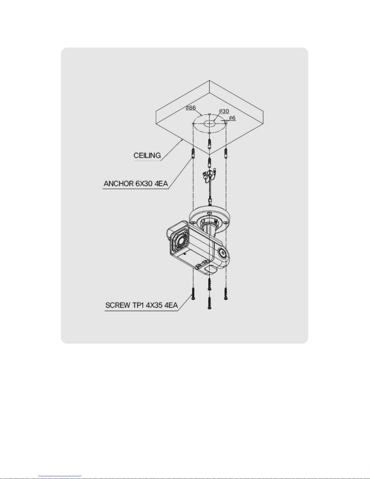
1.3.4 CEILING MOUNT
1. Make a hole of 30mm in diameter for pass ing cable.
2. Using the mount hole pla te, drill four holes on the ceiling.
3. Insert the anchors.
4. Fix the screws.
14
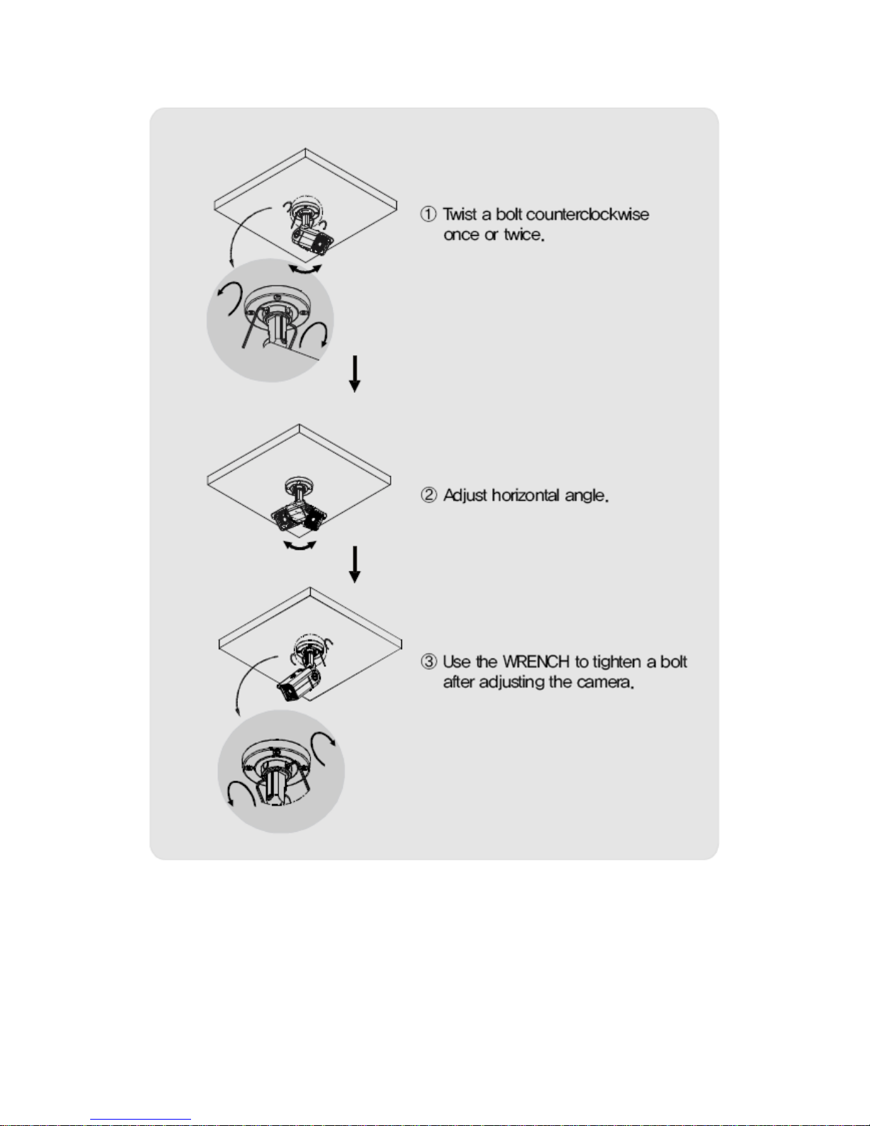
<Adjust horizontal angle>
15
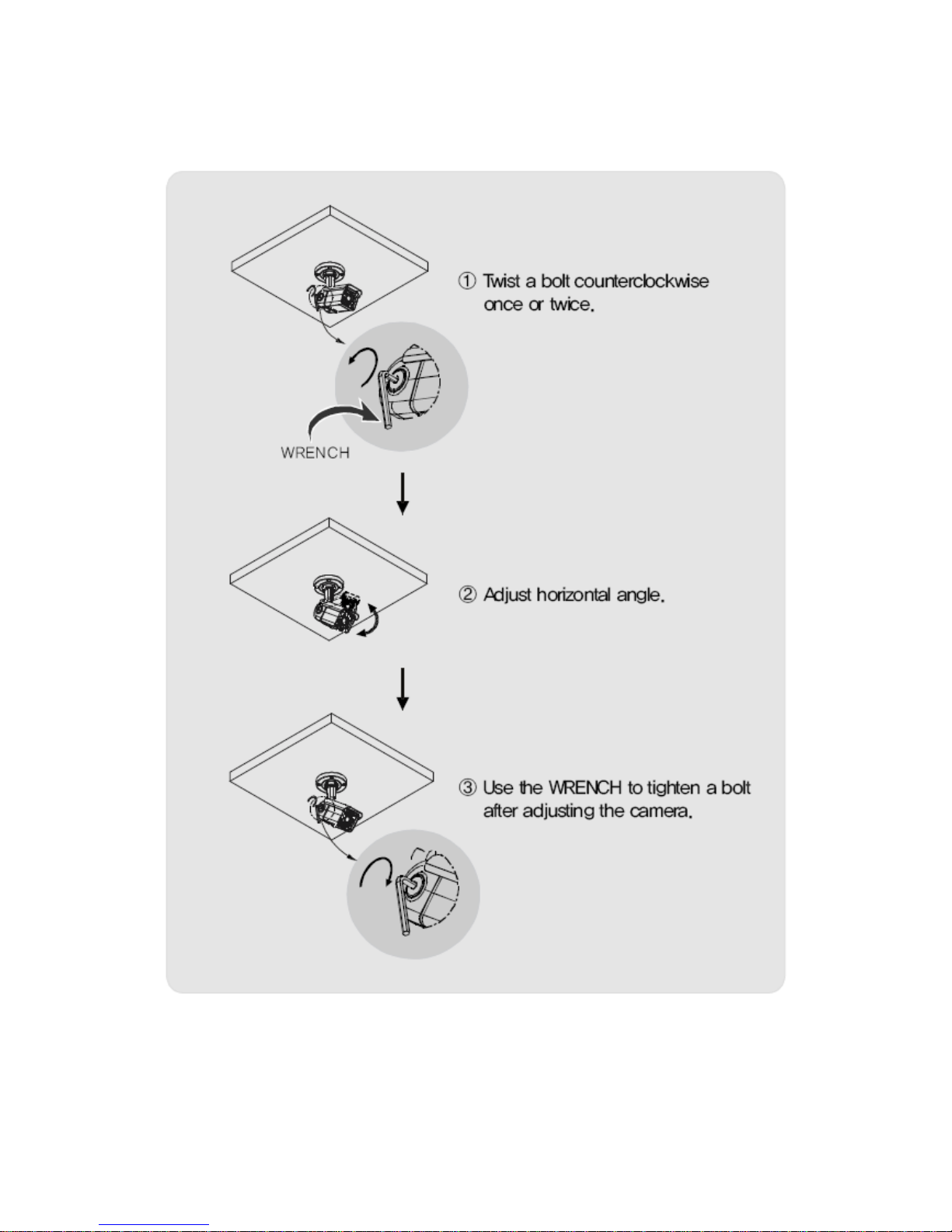
<Adjust vertical angle>
1) Loos en a bolt to adjust ver tical angle of the ca mera.
2) Use the WRENCH to tigh ten a bolt a fter adjusting the camera.
16
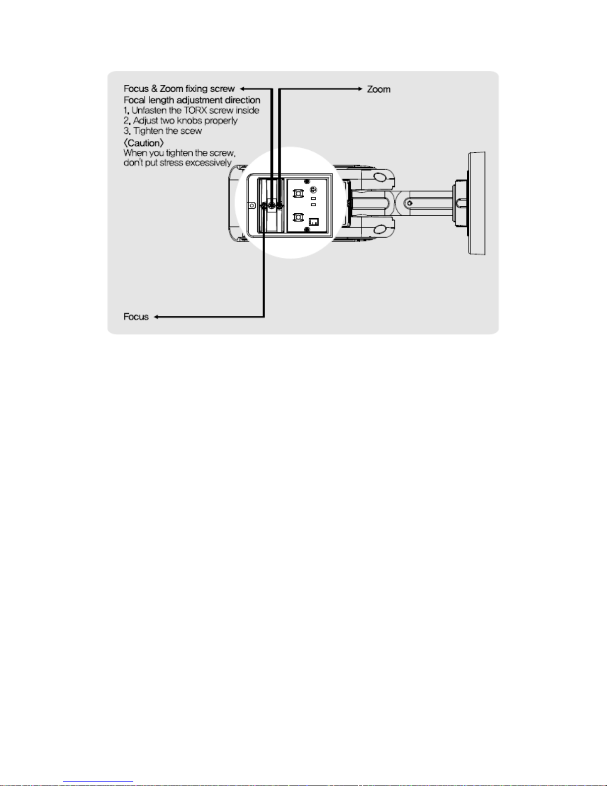
1.3.5 Focus adjustment
(1) Turn the fixing screw in a counterclockwise to loosen the screw.
(2) Adjus t the lever when you get the image s you want.
(3) Turn the fixing screw in a clockwise tigh tly to fix the screw.
17
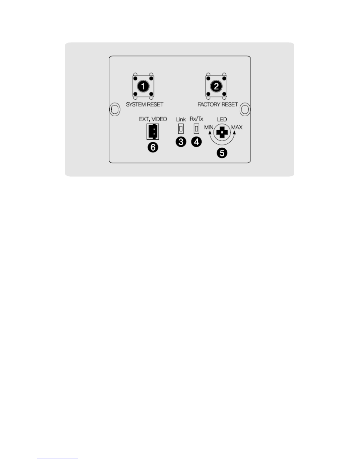
1.3.6 Control board
① SYSTEM RESET: Press the button to reset when the unit is not working normally.
② FACTORY RESET: Turn on the power and wait 2 minu tes. Press the button for 3
seconds to set the ID and Passwords for adm inistration and IP setting values to
the Factory default.
[Reference] Please refer to 2.2 Video Check in Chapter 2 and Chapter 5. System
Setting regarding default value .
③ Link: Ligh t would turn on when the LAN cable is connected to the unit.
④ Rx/Tx Light would turn on when the us er connect by the ne twork.
⑤ LED: Increase or decrease the volume of light from LEDs. Adjus t the volume o f
light according to the distance between the camera and the object.
⑥ EXT. VIDEO : Extra video ou tput terminal for ins tallation.
Plug your tes t monitor in hea r. The cable is option

18
1.4 Specification
1.4.1 Camera Specification
Item
Specification
Type
Megapixel network camera
Image Sensor
1.3 Mega Pixel SONY CMOS Image Sensor
Total pixel
1384 (H) × 1076 (V) approx. 1.48M pixels
Effec tive pixel
1329 (H) × 1049 (V) approx. 1.39M pixels
Scanning System
Progressive Scan
S/N ratio
50dB
Video output
CVBS : 1.0Vp_p / 75 Ω compos ite for installation
Resolution
1280 x 1024 / 1280 x 960 / 1280 x 720 / 640 x 480 / 320 x 240
Min. illumina tion
0.01 Lux (Sense up Auto x 4):LED OFF
0 Lux(25 Range):LED ON
Alarm input/ou tput
Input:1,ou tput:1
IR LED
24PCS
Lens
Vari-focal auto iris megapixel lens
1.4.2 Camera Function
Item
Configuration
DAY&NIGHT
Auto, Color, B/W
WDR
Step 1~ S tep 5, Back light, Front light
Sense up
X1 ~ X6
Brightness
Adjustable
Contras t
Adjustable
Sharpness
Adjustable
White Balance(AWB)
Auto, Indoor, Outdoor, Fluorescent, Manual
Saturation
Adjustable
Edge Enhancement
Adjustable
Negative
Off, On
Pattern Generator
Off, On
Slow shutter
Level 1 ~6
EZOOM
X1 ~ X12 Selectable(Available with CMS only)

19
1.4.3 Network Specification
Class ification
Item
Specification
Summary
OS
Embedded Linux
Network Inter face
RJ45 10/100Bas eT, Ethernet
Setting
By web browser
Network support
Leased Line, Cable Modem, Support Dynamic IP
and Static IP. ADSL usable under Router
Supported Protocol
TCP/IP, U DP/IP, RTP, RTS P, RTCP, NTP, HTTP, DHCP,
FTP, SMTP, DNS, DDNS
Security
USER AUTHENTICATION
PC OS(Viewer)
WINDOWS XP, VISTA, WINDOWS 7
Web browser
IE 7.0 or higher
Audio
Audio Input / Ou tput
Mic In, Line out
Audio compression
G.711 μ-law
Audio communication
One-way
Image
Compression
H.264, MPEG-4, MJPEG
Resolution
1280 x 1024 / 1280 x 960 / 1280 x 720 / 640 x 480 /
320 x 240
Compression Rate
200:1(Typical)
Frame Rate
MAX. 30fps (@1280X1024)
Bit Rate
64 ~ 6000Kbps
Function
Simultaneous Access
Max. 10 users
Video Recording
Recording in client PC with CMS or
FTP Server upon Alarm Event
Motion De tection
Support
Privacy Zone
Support
OSD
Support
Alarm Inpu t / Output
Input 1, Ou tput 1 – Digital output, Open collector
Dynamic IP
Support
IP Router
Support
DDNS
Support
1.4.4 Electric Specification
Class ification
Specification
Power Supply
Regulated 12V DC, PoE(Power over Ethernet)-IEEE802.3af Class 0
Curr ent Cons umption
MAX. 1A( 12V DC)IR LED ON
20
Operation Temp.
-10℃ ~ 50℃
Preservation Temp.
-20℃ ~ 60℃
Dimension
79(W) X 76.5(H) X 172.3(D)mm
Weight
1.22Kg
※The specification is subject to change without any prior notice to improve the quali ty.
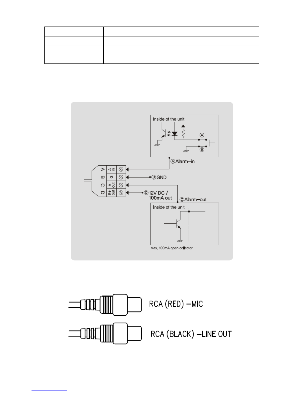
1.4.5 Alarm Input/Output
1.4.6 Audio Input/Output
21
Chapter 2. Installation and Video check
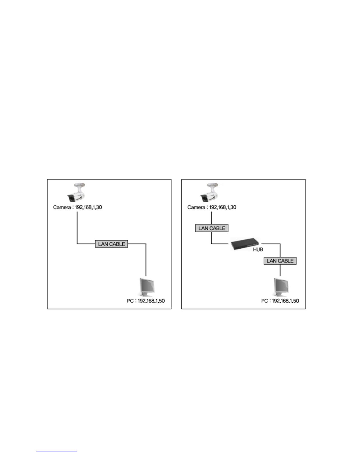
2.1 Installation
On the assumption that User PC and the camera are used under static IP,
and the ca mera is to be directly connected with Us er PC or Local Network,
The installation procedure is to be;
(1) Connect the camera and PC with LAN cable(Direct cable or cross cable).
(Please use the direct cable if you connect to local network)
(2) Power on camera.
* Using regulated 12V DC 500㎃( No IR LED model) or 1A (Built-in IR LED model)
* Using PoE(Power Over Ethernet) : This camera adopted PoE that s upplies power in addition
to data sending and receiving us ing LAN cable without separate power connecti on and it
provides convenience for us ers at installation. When you connect the camera with PoE and DC
adaptor, only PoE is used.
(3) Wait abou t 2 minu te after on ca mera, the system will be booted.

22
2.2 Video check
Bas ic network setting value of the unit is to be;
To connect the unit in user's PC, change the setting value of PC network environment.
Set IP Address , Subnet Mas k and Gate -way of us er's PC with 192.168.1.50 /
255.255.255.0 / 192.168.1.1 as shown on [Pic. 2-1].
[Caution] Be fore changing the setting value, please memorize the previous setting value
on your PC.
2.2.1 Change the setting value of PC ne twork environment
[Pic. 2-1] Ne twork Se tting for User PC

23
2.2.2 Connect the camera with web browser
[Pic. 2-2] Web browser address Input
(1) Run web browser as shown [Pic. 2-2].
(2) Input 192.168.1.30 (de fault value) in URL and press "ENTER " button.
(3) And then, [Pic. 2-3] is to be shown.
[Pic. 2-3] Main Homepage
(4) In case [Pic. 2-3] does not appear, press "factory res et" button for 5sec to reset hardware.
(5) Shown [Pic. 2-3], ins tallation is complete.

24
2.2.3 See the video
Shown as [Pic. 2-3], input ID and pas s word and click on “Viewer ” to see the video feed.
User’s authority to see the video feed is as follow
I D
Pass word
Authority
Detail
admin
admin
All
Stream,
Web management
root
root
All
Stream
guest
guest
View only
Stream
[Table] Us er ID, Password, Authority
[Caution] You must change default value of ID/Password into new ones after installation
2.2.4 Active-X auto installation
If connecting to a camera for the firs t time, you wi ll see the ins tallation message.
Click "install" on the security certificate to load the Active -X control. If you choos e
"Don't ins tall", the web viewer would no t work.

25
[Pic. 2-5] ActiveX Download

26
2.2.5 Installation complete
Upon ins tallation, Web Viewer [Pic. 2-6] appears and image o f camera is to be s een.
[Pic. 2-6] Web Viewer
Installation and check video are completed successfully.
Must change ID/PASS WORD.

27
2.2.6 Net Viewer description
Item
Descr iption
① S tream
selection
Select stream codec and resolution menu related to live-view was
defined only by the admin.(H.264/MPEG/MJPEG)
② Window s ize
Default size is 640X480. Adjust the screen to the optimal size
(Recommendation : Select the same size with stream resolution)
③ Connection /
Disconnection
Connect or disconnect to the stream
④ Recording
Saves the stream as a moving picture file in the .avi format
⑤ Capture
Saves the snapshot as an image file in the .bmp format
⑥ Saving path
Specify the file saving path
⑦ Audio On
Audio On/Off
⑧ Camera name
Display camera title
⑨ Date
Display the date
⑩ Time
Display current time
⑪ S tatus Icon
Display the site information such as Day/Night, Motion, Alarm
input/output
⑫ S tream Info.
Display the stream information such as Audio and recording
condition

28
Chapter 3. Network Setting
3.1 Check Network and Installation Type
This Chapter is for bas ic setting regar ding Network. To ins tall hardware,
bas ic understanding o f ne twork is required.
[Warning] The se tting value might be different in accordance with network environment of user's PC.
[Reference] Please refer to Appendix for better understanding.
There are two ways to install hardware.
1. Install the camera without IP sharing device.
2. Install the camera under IP sharing device which is required PPPoE environment.
This explanation is based on upon default value of ex -fac tory.
[Caution 1] Check video before installation, on 'Chapter 2.Installation and video check'.
[Caution 2] In case using IP sharing device, only global IP is available.
[Caution 3] This unit doesn't support PPPoE directly. So, IP sharing Device is required to
connect to the camera.
<Installation without IP sharing device>
ㆍFor static IP, re fer to '3.2.1 S tatic IP Se tup'.
ㆍFor dynamic IP, re fer to '3.2.2 Dynamic IP Setup'.
<Installation with IP sharing device>
ㆍShould set up with S tatic IP, re fer to '3.3 Installa tion with IP sharing device' .
3.2 Installation without IP sharing device(router)
3.2.1 Static IP Setup
(1) Connect the camer a to PC with LAN cable( direct cable or cross cable).
(2) Cable connection and network setup s hould be same as in 'Chapter 2. Ins tallation and video
check'’
(3) Connect the camer a to Web.
Run web browser and input h ttp://192.168.1. 30(default value) in URL and
press "ENTER" button then [Pic. 3-1] will be shown.

29
[Pic. 3-1] Main Page
(4) Administration page log -in
Shown as [Pic. 3-1], input ID and pas s word and click on “Mana ger” to see the admin page.
[Caution] If you logged in first in adminis trator mode, please change the password
and ID of administrator.

30
(5) Network Setting
Click 'Netw ork Setting' on [Pic. 3 -3], [Pic. 3-4] appears .
[Pic. 3-4] Ne twork Se tting
(6) DNS Server Setting
For setting o f DNS server, input DNS address to fit with ne twork environment to set(Defaul t address
is DNS address of 'Dacom', 'Hanaro telecom').
Use DNS value normally set in PC. DNS address should be necessarily input. Click
button to s ave setting value.
(7) IP address setting
Click 'Static IP Address ' in 'IP Setting' of [Pic. 3-4], and inpu t IP Address ,
Subnet Mask, Default Ga teway according to ne twork environment.
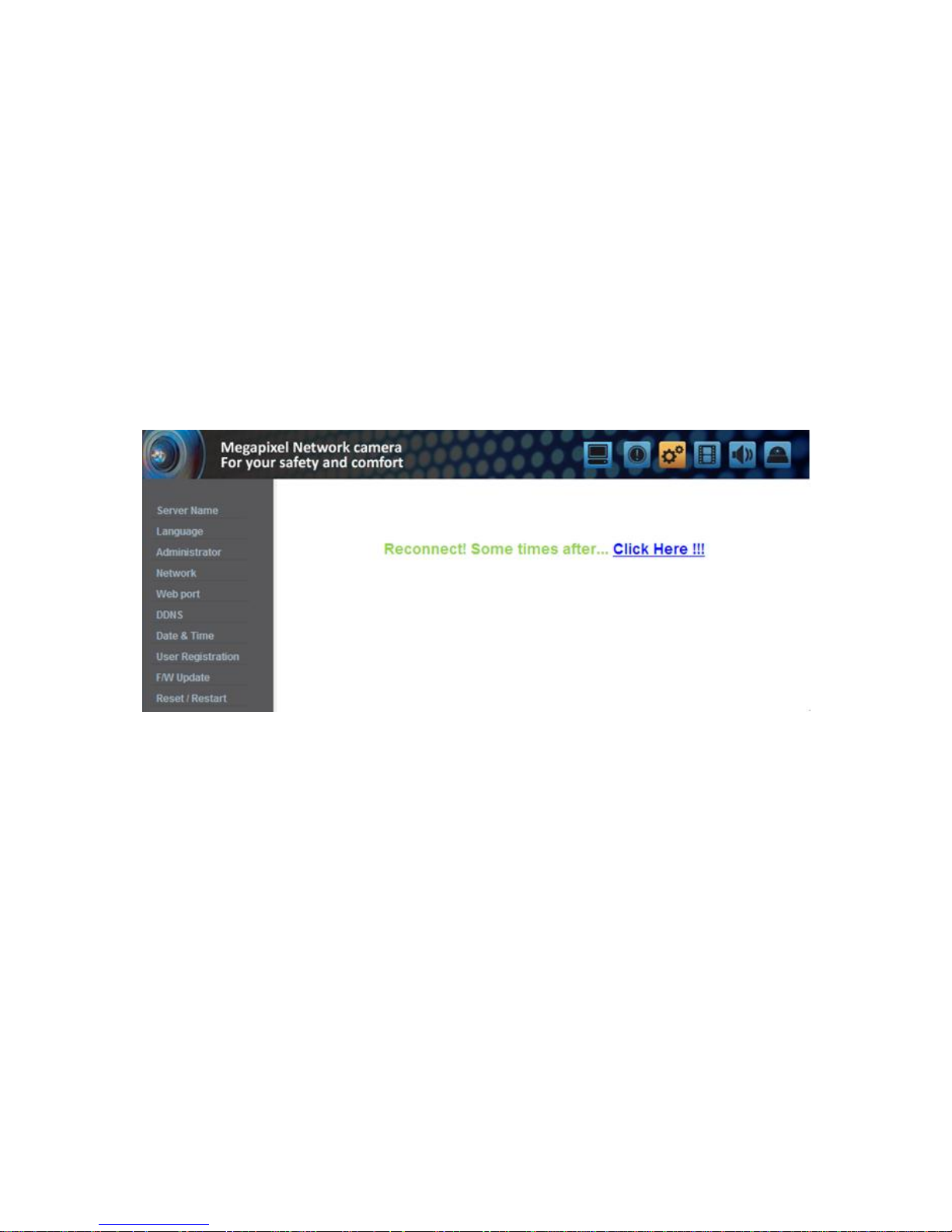
Click button to s ave setting value. Click 'Clic k Here' upon appearing of IP change window of
[Pic. 3-5] As IP Change page appears as [Pic. 3-6], the main page of changed addres s is
connected.(May not find the main page o f changed address under cross cable connection, bu t IP
has been changed.)

31
[Pic. 3-5] IP change
[Pic. 3-6] IP Change page

32
(8) Remove LAN Cable(cross cable) connected between the camera and PC.
(9) Connect the camer a to ne twork wi th LAN cable(Direct cable).
(10) Connect PC to network with LAN cable(Direct cable).
(11) Set up IP address, Subnet Mask and Ga te way of PC according to network environment
(Recommended to us er to remember the value before changing user's PC setting).
(12) Check
Run web browser on PC, inpu t IP address set in the unit onto URL and click as [Pic. 3-7].
When main page appears as [Pic. 3-1], click Viewer button to connect to web viewer and check
if IP setting is correct or not.
(Refer to 'Chapter 2. Installation and video check')
In case video is not seen, check whether there may be conflic tion o f IP in network, and recheck
the set value of network environmen t of the ca mera, and network environment of User's PC.
[Pic. 3-7] Connect to the unit
[Reference] If you regis ter on DDNS server we operate, you can us e the registered
domain name for connection.
3.2.2 Dynamic IP Setup
Do no t s et up dynamic IP in the unit except directly connecting the camera to network supporting
dynamic IP. If the IP has not been allocated to the unit in dyna mic IP s etting, plea s e press the
'FACTORY RESET BUTTON' for 3 sec , then try to setup again.
(1) Connect the unit and PC with LAN cable(cross cable).
(2) Cable connection and network setting s hould be done same as
'Chapter 2. Installation and video check' and check video.
(3) Go to network setting page of administrator's page as per (3),(4),(5) o f 'Sta tic IP Setup'
If you will no t connect provided internet line from ISP(In ternet service provider) to unit via router
and you will connect to unit directly, we recommend to you to keep the MAC address on the
network setting page. It needs to when regis ter to DDNS server.

33
[Pic. 3-8] Network Setting
(4) DNS server setting
For setting o f DNS Server, input DNS address to fit with ne twork environment to set(Default address is
DNS address of 'Dacom', 'Hanaro telecom').
Use DNS value normally set in PC.
DNS address should be necessarily input.
Click Save button to save setting value.
(5) Dynamic IP address
Click on 'Dynamic IP Address' in 'IP Setting'.
Click Save button to save, and [Pic. 3-9] w ill be shown.
[Pic. 3-9] Dynamic IP Setting

34
(6) Remove LAN cable(cr oss cable) connected between the ca mera and PC.
(7) Connect the camera to ne twork with LAN cable(direct cable).
(8) Connect PC to Networ k with LAN cable(direct cable).
(9) Set up IP address, Subnet Mas k and Gate way of PC according to network environmen t.
(10) Installa tion check.
If you have the DHCP server to ass ign an IP Address :
First close the web brows er, you can find out the IP add ress using program of "IP Manager" in
installation CD (Please refer to "9.1 Use of IP Manager")
If you found the assigned IP to unit righ tly, open the web browser, input IP addre ss of the camera
then press the "ENTER " key. The main page will be s hown as [Pic. 3-1]
If you couldn't find the unit, it means IP has not been allocated to the unit so you have to press the
'FACTORY RESET BUTTON' for 3 sec then try to again.
If you turn off the camera and reactivating in dynamic IP environment, might be change the IP address.
So if you register the IP address to DDNS server, you can use the domain name.
3.3 Installation with IP sharing device(router)
3.3.1 General Ins tallation
(1) Connect the camera and PC with LAN cable(cross cable).
(2) After checking video in '2. Installation and video check', then go to the next step.
(3) Go to network setting page of Administra tor's page as per 3), 4), 5) of '3.2.1 Static IP Setup'
[Pic. 3-10] Network Setting
35
(4) DNS Server Setting
For setting of 'DNS server', input DNS address to fit with ne twork environment to set.
(Default address is DNS address of Dacom', 'Hanarotelecom'.)
Use DNS value normally set in PC. Click Save button to save the setting value.
(5) IP Address Setting
Click 'Static IP Address' in 'IP Setting' of [Pic. 3 -10], and input IP Address , Subnet Mask, De fault
Gateway(Please refer to the manual of IP sharing device) and click button to save the setting v alue.
Click ‘Save’ bu tton to sa ve the setting value.
When [Pic. 3-11] appears , click 'Click Here' to go to changed main page.
(In case of connecting wi th cross cable, may not found the changed page but IP change has been
completed)
[Pic. 3-11] IP change
(6) Connect the camer a to IP sharing device with LAN cable(direct cable).
(7) Connect PC to IP sharing device with LAN cable(direct cable).

36
Chapter 4. General Information
1. General Information
User can find product information as like H/W version, F/W vers ion, and the URL for RTSP
connection.

37
Chapter 5.System Information
5.1 Camera Name
Server title would be shown on the top of the video when you see the video by the viewer. Server title
is to be Englis h without space(Max. 10 characters).
Click ‘Save’ bu tton to sa ve title after inpu tting name.
5.2 Language
This is to select language to be displayed in all web pages s uch as Administrator's page, web viewer
and main page.
* Now, English and Korean are available.

38
5.3 Administrator's ID and Password Change
Adminis trator's ID and password should be English, within 20 characters, without space.
Click 'Save' button to s ave the changed value after changing Administrator's ID and pass word. In cas e
of forgetting Administrator's ID and pass word, click ' Factory Se t' bu tton for 3 s ec to return to ini tial
value, and change Administrator's ID.
<Cau tion> Change Adminis trator's ID and password and do not disclose the in formation
to others.
5.4 Network Setting
This is to set ne twork. Set ne twork to fit us er's network environment in '3. Ne twork Se tting'. Change
network information to fit environment for the unit to be ins talled in.
5.5 Web port
Set a web port. Web port used to access the camera via the web browser. The default is 80.
When several network cameras are connected to one IP Rou ter, you should forwar d the web por t of
the router to the web por t of a connected camera.
You can change the ports of the camera except the specified por t.

39
5.6 DDNS
DDNS is an abbreviation of Dynamic Domain Name Service that conver ts the IP address of
a camera into a genera l Host Name so that the us er can easily remember it.
1) Click [Enable].
2) Enter the product domain name(over 4 characters) and email address.
3) Perform the duplicate check for the domain tha t you entered by clicking [Check].
4) Click [Register], then you s hould make sure whether the Status is ‘Regis ter OK’ or no t.
5) Click [Unregis ter] to delete registered domain name.
5.7 Date & Time
There are two ways of time s etting as follow.
Auto(NTP) : This is to set up local time in cas e of monitoring from di fferent time zone area. Select one
of time zone in 'Time Zone' and save.
User Set : This is for user to s et up time directly. There can be s ome gaps between local and time of
the unit.
Daylight Saving Time (DST) : Set up the Dayligh t Saving Time. Setup the “Begin : month/week/day of
week/time” and “Finish : mon th/week/day of week/ time” a fter checking the ‘Enable ’ box, it will be
shifted back one hour during setting period.
Caution: The time is changed to defaul t time when the camera reboot.

40
5.8 User Registration
This is to regis ter an account of user who monitors and controls video.
Adminis trator's ID and pass word s hould be English, within 20 characters , without space. Allow the
authority to us ers and click 'Save' button. A maximum us er to allow registration is 20 persons.
Click ‘Delete’ for dele ting user.
41
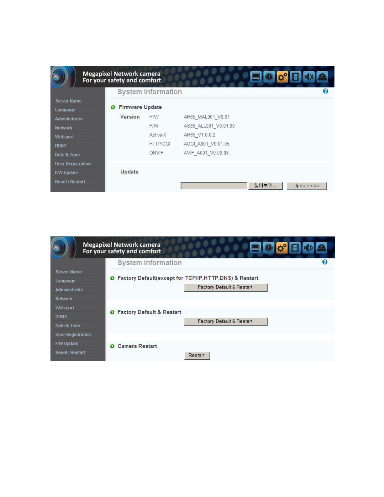
5.9 Firmware Upgrade
In case firmware is upgraded in the near fu ture, our upgrade server(http://iplinker.net) w ill
automatically upgrade firmware of the unit.
5.10 System Reset/Restart
This is the function to res tart the camera system.

42
Chapter 6. Stream Information
6.1 Video
1) Image mirror
Select a video s ource mode(Normal, Flip, Mirror, Both)
2) Resolution
Set the video size . This camera supports 2 kinds of res olution simultaneously.
3) Stream Setting
Set the stream. This camera s upports 3 kinds of s tream simultaneously.(H.264, MPEG4,
MJPEG)
Choos e the input source of res olution and codec.
* Supported resolution : 1280*1024, 1280*960, 640*480, 320*240
Supported codec : H.264, MPEG, MJPEG
* The combination o f H.264 & 1280 * 1024 is recommended for broadband network and high
performance PC.

43
6.2 Audio
You can configure the I/O settings of the audio source from the ca mera.
6.3 RTSP Setting
This camera provides the RTSP/RTP s trea m trans miss ion as well as TCP/IP stream. The function is
based on VLC(http://www. videolan.org/ ) media player.
If duplicated por t used in this function with the p ort us ed from o ther process, i t will no t be working
well.
RTSP Port : Setting of RTSP port.(de fault port: TCP 554)
RTP Port range: Setting the port of RTCP with RTP
* The maximum and minimum have at leas t 3 range gap.
RTCP:
- RTCP Time out enable : If the server do not receive the RTCP from Clien t then RTSP session will be
stopped
Use user au thentication :
- Enable : To set using for us er authority on RTSP session
MULTICAST: Multicas t function trans fers the data to multiple users by a single streaming transfer. It
loaded less traffic in the network than unicast. There should, however, be multi-cas ting functions in
all network equipmen t which is in located in be tween streaming server(camera) and clients .
-IP address: D Class IP address should be allocated for the mul ti cas t.
D Class IP address is 224.0.0.1 ~ 239.255.255.254.
-Port: 4,000(default por t)

44
-T ime to live(TTL): TTL is reduced one by one when it is transferred each router. When it reaches to
"0" value, the router will d is card the data. The TTL Value determines how far the da ta is delivered.
Generally the value is 128.
6.4 OSD
Configure the settings as necessary of OSD in s trea m.
45
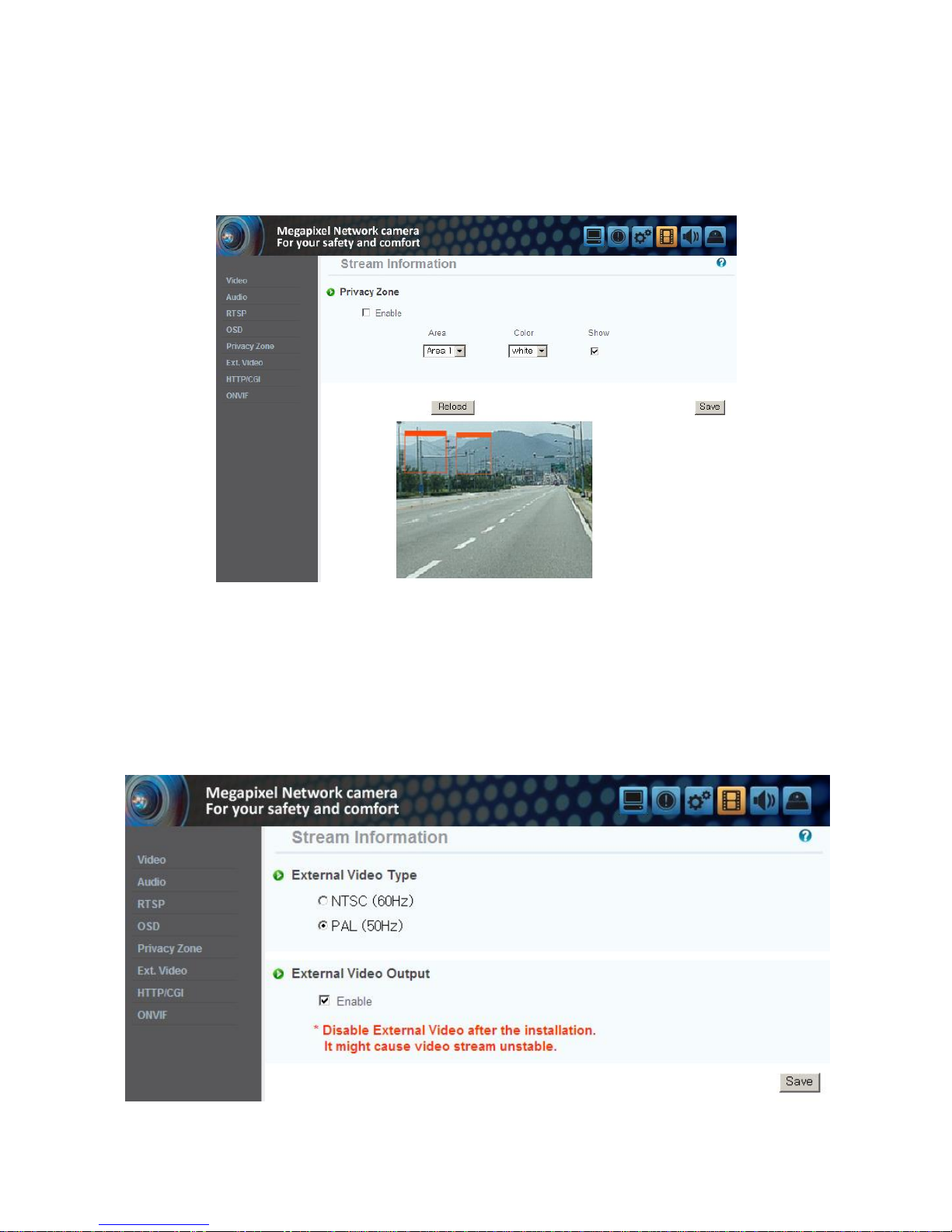
6.5 Privacy Zone
You can s pecify a certain area of the camera video to be pro tec ted for your privacy.
Check the ‘Enable ’ to activa te the function. ‘Show ’ is to specify the privacy zone.
* You can specify up to 6 zones .
6.6 External Video
Analog video output for installation.
You can set the video ou tpu t type to either NTSC or PAL.
Default is set to ‘Enable’.
After installation, you mus t dea ctivate this func tion to improve camera performance.
46
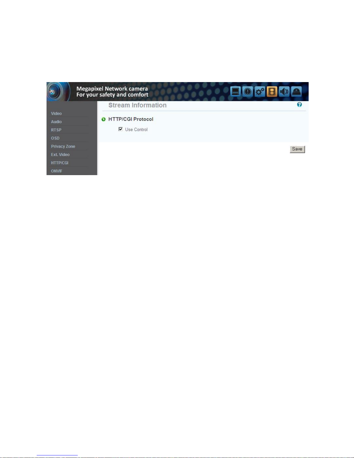
6.7 HTTP/CGI
This function transfer the stream by using Server Push method and can use the control function by
CGI calls.(EX. Port I/O control)
Good poin t of this function is using web por t , so it is able to transfer the stream and contro l which is
not affected by fire wall.
47
Chapter 7. Event Information
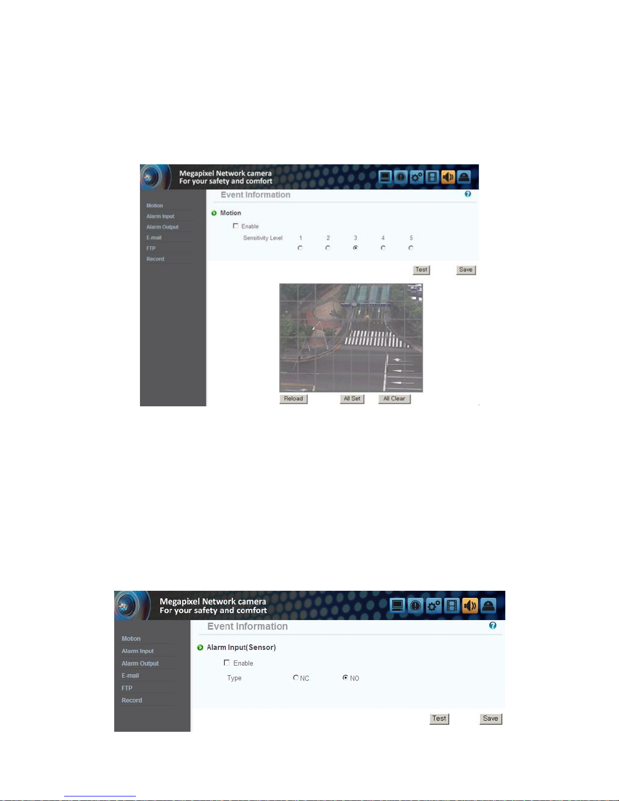
7.1 Motion
Enable : To us e motion de tection function, click ‘Enable’.
Sensitivity Le vel : Setting up sensitivity to de tect motion to adjus t input video by situation. You can
select 1~5, and 5 is the highest.
7.2 Alarm Input
1) Alarm Input
Click ‘Enable ’ to activa te the alarm input function.
2) Type
Select Normal Close(NC) or Normal Open(NO).
Circuit of N/O type is us ually open, and the activa tion o f the sensor occurs at the time of clos e, a nd
N/C type works reverse way.
* Alarm inpu t can be interlock alarm ou tput, email no tification and FTP.

48
7.3 Alarm Output
1) Alarm Output
Click ‘Enable ’ to activa te the alarm outpu t func tion .
2) Linkage
Alarm input : Alarm output function operates only by alarm input event.
Motion : Alarm output func tion operates only by motion event.
3) Dura tion Time
Set dura tion time upon alarm events.
4) Test
Alarm output is activated by compulsion and you can check the action internally.
7.4 E-Mail
You can configure the E-mail s etting so that you can s end email to your PC if an even t occurs.
* The 'Subject' should be within 30 characters and the 'Message' should be within 50 characters.
49
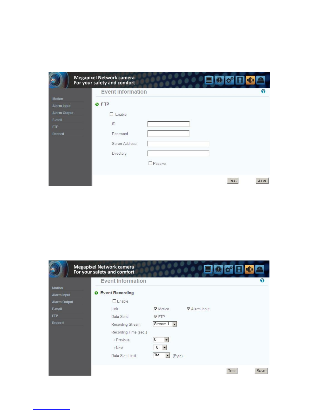
7.5 FTP
1) FTP Server : To send the recorded video to FTP server upon alarm event,
Input FTP server address, folder name, user IP and password,
Pass ive mode : Select it if you need to connect in passive mode due to the firewall or the FTP s erver
settings .
7.6 Recording
You can con figure the even t recording settings s o that you can trans fer the images stored in the
camera to the FTP server if an even t(mo tion or alarm input) occurs .
Da ta send : Check to trans fer the images to FTP s erver.
Recording Stream : Choose the stream to record.
Recording Time : Set the recording time poin t be fore and a fter the occurrence of the event.
Da ta size limit : Specify the maximum data size.

50
Chapter 8. Camera Information
8.1 Day & Night
This menu is to set IR Cut filter, IR LED On/O ff, Color and B/W mode.
Auto : Automatic day(Color) & nigh t(B/W) switc hing by setting value.
P lease set the value properly according to the environment.
Day : The pic ture is always displayed in Color(us ing IR cut filter).
Night : The picture is always dis played in B/W(Don't use IR cut filter).
Activate IR LE Ds : Checked this menu, IR LEDs turn off or on according to Day or Nigh t mode. If not
checked it, IR LEDs are always off.
8.2 Color
You can change the camera color settings according to the environment where the camera is located.
* Sharp : Adjust the sharpness of picture. As the le vel of s harpness increases, the screen gets
sharper and the level o f nois e als o increases.
* Edge Enhance : The higher the level is, the sharper and clearer the outline of the image becomes.

51
8.3 White Balance
Auto : Adjus t white balance automatically.
Indoor : Adjust white balance to indoor environment(3200˚K).
Outdoor : Adjus t white balance to outdoor environment(5600˚K).
Fluorescent : Adjus t white balance to fluorescent environment(4000˚K).
User : User can adjus t the red and blue gains of the camera video manua lly.
8.4 WDR
It displays a sharp image of the objects in a s cene where both brigh t and dark areas exist.
Back-light : Enha nce the object image contras t when light is coming from back of it.
Front-ligh t : Enhance the object image contras t when light is coming from front of it.
* At nigh t, WDR func tion is not available.

52
8.5 Digital Noise Reduction(DNR)
It is us ed for reduce noise in the pic ture at low luminance.
8.6 Effect
Color Bar : Display color bar picture.
Mono : Change color picture to B/W.
Negative : Reverse the brightness and color.
8.7 Sense Up
This is relating to s ense up function. Low s hutter speed which can gather more light by increas ed
exposure of the light is suitable for the dark circumstances and at night. Using this mode, you can
distinguis h the ou tline and the color o f the objec ts. Bu t, regarding mo ving objects, its ou tline migh t
not be clear. And excessive Sense up func tion migh t e ffec t on motion de tection.

53
8.8 Shutter Speed
Adjust the electronic shutter of the camera.
Auto : Control shutter speed from 1/30 to 1/ 9000 s econd automa tically to have the bes t image
depending on the variable light condition
Suppress Rolling / S trong : Shutter s peed is fixed between 1/30, 1/40, 1/60 and 1/120 automa tically
depending on the variable light condition.
Because shutter speed is sy nchronized with frequency of fluorescent ligh t, rolling noise under the
fluores cent ligh t is s uppressed. It is als o recommended in dim indoor environment.
Suppress Rolling / Weak : It works same the way as Strong mode when s hutter speed is between 1/30
and 1/120. Bu t, when environment is brigh t to require shorter s hutter than 1/120 s ec, it works the
same way as auto mode. Under s trong fluorescent light, this could not suppress rolling noise.
* User : Adjust the shutter s peed of the camera manually. Specify the AGC manually.

54
Chapter 9. IP Manager
9.1 Use of IP Manager
This program is the utility to find out the unit connected to local network. It is useful for the
application of the unit connected by DHCP function.
It can provide you the in forma tion such as IP address, MAC, web por t for easy ins tallation and us e.
9.1.1 Run IP Manager program
Double click "IP Manager" file to open the program, [Pic. 5 -1] will be s hown.
[Pic. 5-1] IP Manager
Description of IP Manager function
NO
Description
NO
Description
1
Select all units of the lis t
9
Gateway in formation of the unit
2
Deselect all uni ts
10
IP type of the unit
(Static IP/Dynamic IP)
3
Delete the list
11
Web port number to connect
4
Scans for cameras that are currently
connected to the ne twork
12
Stream port number
5
Consecutive number of the list
13
The cameras that are currently
connected to the ne twork
6
MAC in formation of the uni t
14
To change the in forma tion
7
IP address of the unit
15
Exit the program
8
Subnet Mask informa tion of the unit

55
9.1.2 Find IP address
Click “Find ” button to find the cameras that are currently connected to the local network.
Below picture will be shown, a fter IP finding comple ted.
[Pic. 5-2] IP finding completed
User can connect eas ily by inputting the in formation of IP address and web port.
9.1.3 Change IP address
After finding IP address , if you want to change IP address, Gateway or Subnet Mask, double click IP
addr ess you want to change or check the list on the “index ” and click “Change”.
9.1.3.1 Change IP address for one unit
<Procedure>
Static IP
① Double click IP address you want to change or check the list on the index and click “Change”.

56
[Pic 5-3] Change of IP address
② Check the “Static IP Address ”, input the informa tion (IP Address , Subnet Mask, De fault
Gateway, Web Port, Stream por t) you want to change.
③ Input ID and pas s word.
④ Click the “Change” button. After a while, setup will be comple ted.
⑤ Click the “Find ” button one more time to check the changed in formation.
Dynamic IP
① Double click IP address you want to change or check the list on the index and click “Change”.
② Check the “Dynamic IP Address ”, the IP Address , Subnet Mask, De faul t Ga teway, Web Port,
Stream port will be grayed out.
③ Input ID and pas s word.
④ Click the “Change” bu tton. After a while, s etup will be comple ted. And you can find the
changed information.
9.1.3.2 Change IP address for multiple units
<Procedure>
Static IP
① Check the index box of two or more units you want to change. Click the “Change ” bu tton.
The picture of next page will be shown.

57
[Pic. 5-4] IP address change window
② Click the “Ba tch” bu tton, the dialog appears.
[Pic. 5-5] IP address change dialog
③ Check the “Static IP Address ”, input the informa tion (IP Address , Subnet Mask, De fault
Gateway, Web Port, Stream por t) you want to change.
④ Input the “Las t Address” and “s tep”.
EX) If the condition sets like the picture 5-5, the last number of the IP address will be
increased each 1, starting 30 and will no t over 253.

58
⑤ Input ID and password, a nd click the “Save ” bu tton. After a while, the changed IP address
dialog appears .(Pic. 5-6)
[Pic. 5-6] Changed IP address dialog
⑥ Click the “Change” button. After a while, setup will be comple ted.
⑦ Click the “Find ” button one more time to check the changed in formation.
Dynamic IP
① Double click IP address you want to change or check the list on the index and click “Change”.
The picture [Pic. 5-4] will be s hown.
② Click the “Batch” bu tton, the dialog [Pic. 5-5] appears.
③ Check the “ Dynamic IP Address ”, the IP Address, S ubnet Mask, Default Ga teway, Web P ort,
and Stream port will be grayed out.
④ Input ID and pas s word.
⑤ Click the “Change” bu tton. After a while, setup will be comple ted. And you can find the
changed information.

59
Chapter 10. Basic Network
This chapter is the bas ic explanation for installa tion.
10.1 Public IP
[Pic. 6-1]Internet environment
All hosts connected to in ternet have the exclusive number called IP address.
Communication among hosts is available by us ing it.
There are two ways to allocate IP address. One is fixed by the way of static IP address
whenever connected to internet. And the other is assigned by a server using Dynamic Host
Configuration Protocol (DHCP). It is Dynamic IP.
In case of Dynamic IP, when turn off the computer, automatically return the IP to DHCP due
to using that IP in circulation.
Determined way o f ass igned IP by networ k pol icy s o please ask to ne twork a dminis trator or
ISP(Internet Service Provider)
In case of using Firewall, the camera might be out o f working. Pleas e ask network adminis trator then
open the service port
60
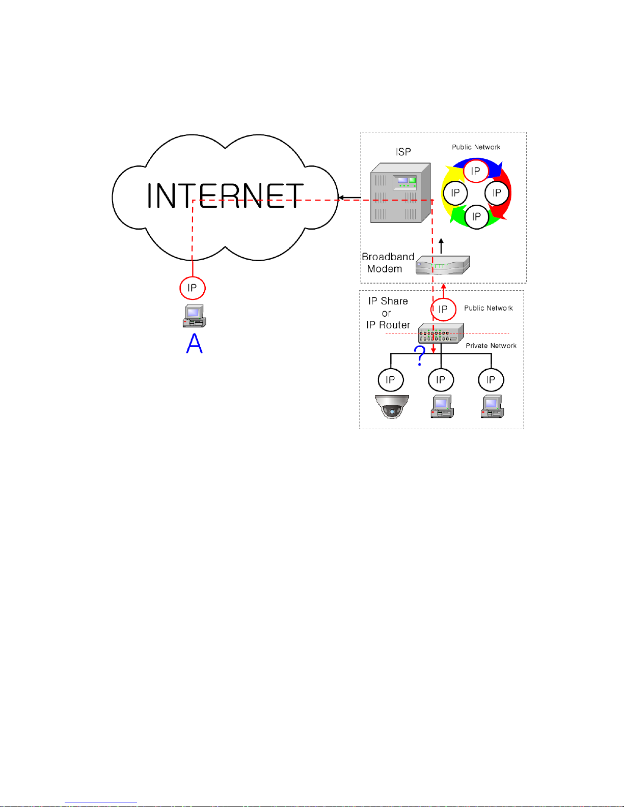
10.2 Private IP
[Pic. 6-2]Internet connection by IP sharing device.
The most common us e of these addresses is in home networks, since most Internet Service Providers
(ISPs) only allocate a s ingle IP address to each cus tomer, but many homes have more than one
networking device (for example, several computers, or a printer). That’s why we recommended use IP
sharing device. IP sharing device uses only one public IP. Private IP is allocated such as
192.168.xxx.xxx, and ca n not be us ed as public IP.
When using the router, connect the router and inpu t IP address of the unit(IP address of the unit is s et
as 192.168.1.8 on ex -fac tory) in DMZ menu.
If the user ca nnot us e the DMZ function because there is no DMZ menu in the rou ter or some other
reasons, go into Por t Forwarding or NAT menu on the router and map the por t of the unit on e by one.
[Reference] Private IP range to use private address is hereby.
CLASS A : 10.0.0.0 ~ 10.255.255.255
CLASS B : 172.16.0.0 ~ 172.31.255.255
CLASS C : 192.168.0.0 ~ 192.168.255.255
* For more detailed in formation, please refer to manual of IP s haring device.

61
10.3 Ping test
Ping is the test to check response among the devices connected with ne twork.
Input "Ping IP address " to command window of PC and check response.
In case of Ping failure, there is some communication problem be tween the devices.
By firewall, this test can not be available.

62
[Ping Failure]
[Ping Success]

63
Chapter 11. Appendix
11.1 Basic setting table
Item
Default(Basic setting)
Remarks
Network
Static IP / Dynamic IP
Static IP
IP Server
Enable
IP address
192.168.1.30
Gateway
192.168.1.1
Subnet Mask
255.255.255.0
Web Connection Port
80
Do not duplicate the s ame Port.
RTSP port
554
RTP port range
5000 ~ 5999
ID and Password
Adminis trator
ID/Password
admin/admin
User ID/Password
root/root, gues t/guest
Domain of Related Ser ver
DDNS Server
iplinker.net
Domain of server to connect to register IP
Stream setting
Stream 1
H.264 15 fps @1280x1024
rtsp://<ip 주소>:554/stream1
Stream 2
MJPEG 15fps @640x480
rtsp://<ip 주소>:554/stream2
Stream 3
None
rtsp://<ip 주소>:554/stream3
Video output
On
After installation, deactivate it
Other setting
Time Zone
Asia/Seoul(Korea)
[Reference] In case to reset hardware and network setting, ID and password of user and
Adminis trator will be automa tically returned to the above default value.

64
11.2. Troubleshooting of cable connection
11.2.1 Power cable connection check
Check if the power cable is connected to the camera properly.
※ Check whe ther the ou tput of the ada ptor is regulated 12V DC 1A(for built-in IR LED model)
or 500mA(for No IR LE D model)
11.2.2 Network cable(LAN Cable) connection check
Check whether the network cable is connected correctly.
[Caution] Use direct LAN Cable or cross ca ble according to network condition. (Re fer to chapter
2 Video check)
① Cable check
[Direc t Cable]
Hold each end o f both side a nd check if s ame color's cable is connected to s a me location in
RJ45 jack or no t.(Connection with IP sharing device or cable modem)
A. B.
[Cross Cable]
Hold each end of both side and check whether 1, 2(Tx +, Tx -) and 3, 6(Rx+, Rx -) ar e cross or
not.(Connection with PC)
C. D.

65
11.3 Troubleshooting of network connection
11. 3.1 Cannot connect with network
Check with "7.2.2 Network cable(LAN cable) and cable connection check". [PING Tes t]
① In cas e camera uses Static/Public IP : inpu t "Ping IP addr ess " to co mmand window o f PC and
check res ponse.
② In cas e camera uses dynamic/public IP : If user cannot find camera's IP address , reset hardware
and connect PC with the camera through cross cable and ping test by en tering "192.168.1.8".
③ In cas e camera uses private IP through IP s haring device : Do ping test of private IP address set
for camera in PC tha t is connected in the local network through IP sharing device.
[Reference] Please refer to "PING Test of Basic Network".
If "ping test"get res ponse, network setting for camera is done correctly.
Ping tes t is okay but there is no connection, check with "7.3.2 check port setting ".
11. 3.2 Check port s etting
If user can't connect wi th camera even though "Ping test" is okay, please check port setting by the
following s teps.
The unit us es 3 ports as follow.
Web Connection Port : Port 80 TCP
Authen tication, Con trol and video s treaming port : Port 9000 TCP
① No t available to connect to web
If it is not available even to connect to web, check web connection por t because web connection por t
may be set with other number is not "80".
Use IP Finder program.(Default value of web port is "80".)
[Reference] Web port "80" can not be available in some internet service.
In this case, go to the administrator's page and change the web port.
② Problem in video monitoring
In cas e there is problem in video moni toring even though there is no problem in web connection,
check if "Authentication and Con trol Port" and "Video S treamin g.
Port" of the unit is s et on IP s haring device(Refer to the manual of IP s haring device regarding P ort
forwarding).
[Reference] It is strongly recommended to register the number under 9999 of por t.
Port Number more than "10,000" can not be available in some network.

66
Chapter 12. Troubleshooting
※If you can not solve the problem, please contact an authorized technician.

67
Chapter 13. Warranty Card
 Loading...