


Version:3.02.28
Easytrac Getting Started
Date:2007/3/1
© 2007 ORION Technology LTD. All right reserved. 1/19

Contents
1. Introduction ............................................................................................................3
I. Package contents: ............................................................................................3
II. Front panel: ..................................................................................................3
III. Rear panel:....................................................................................................4
IV. V-16 Cable pin assignment: .........................................................................5
2. Configuration..........................................................................................................6
I. Hardware and Software preparations .............................................................. 6
II. Configuration step by step ...........................................................................7
III. Running on normal mode........................................................................... 11
IV. Test protocol commands via RS-232 connection.......................................16
V. Get the system logs via RS-232 connection for advanced debugging..........17
© 2007 ORION Technology LTD. All right reserved. 2/19
1. Introduction
I. Package contents:
1. Easytrac x 1 (with 700mAh Ni-MH backup battery)
2. GSM quad-band antenna (850/900/1800/1900) x 1
3. GPS active antenna x 1
4. V-16 cable x 1 (with 16-pin connector and 10A fuse)
5. AC adapter x 1
6. Vehicle power adapter x 1
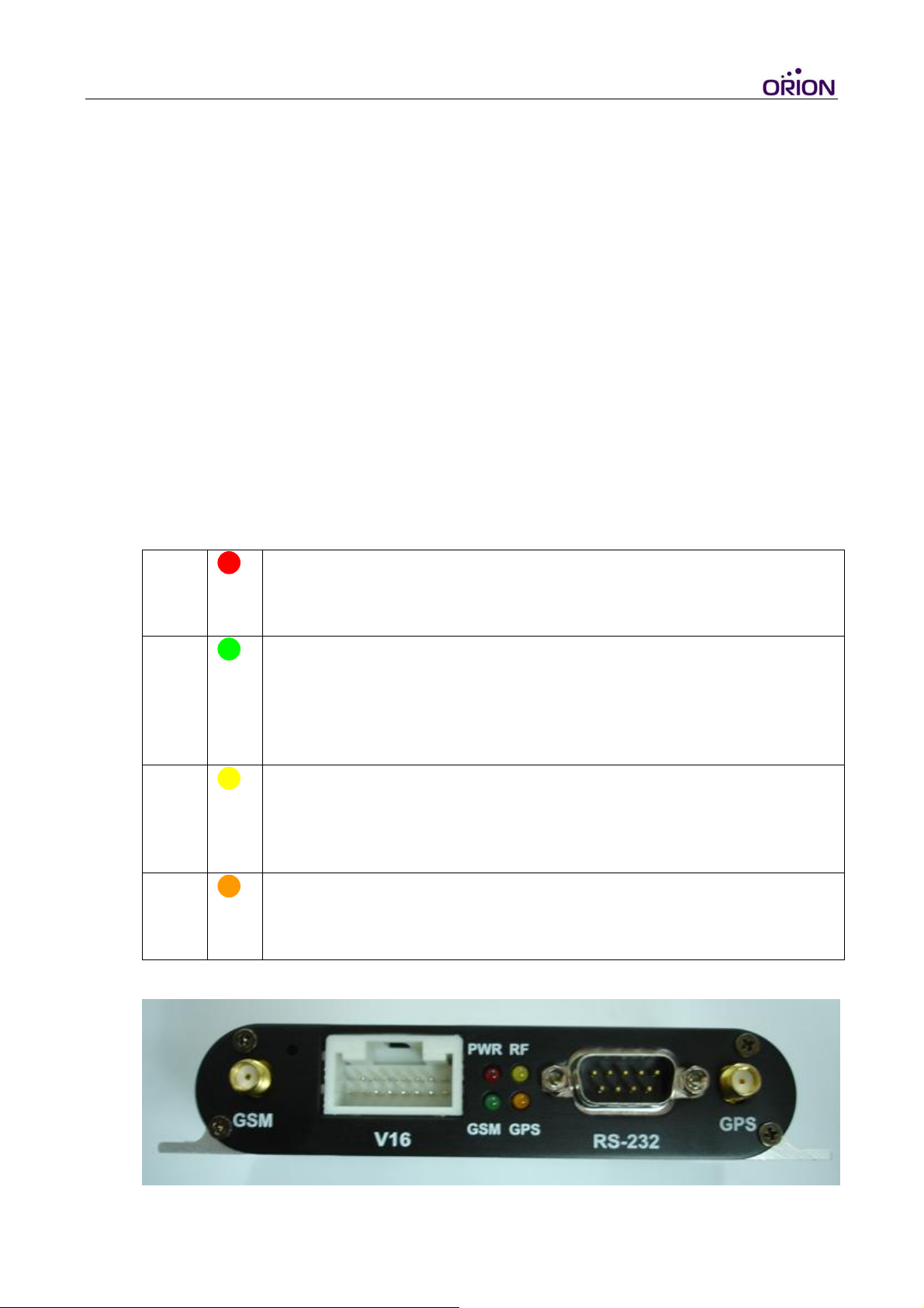
II. Front panel:
1. GPS antenna jack (Right side of the panel)
2. GSM antenna jack (Left side of the panel)
3. RS-232 connector (For configuration and debugging)
4. V-16 Connector
5. LED indicators
PWR
GSM
RF
GPS
OFF: Power OFF
DIM: Backup battery power low
ON: Power ON
OFF: GSM module OFF or Error, No SIM Card, Searching networks)
Flash: GSM registered (0.5sec ON 0.5sec OFF)
Flash: GPRS connecting (0.25sec ON 0.25sec OFF)
ON: Socket session online (connect to tcpserver running on the
Gateway Server which is the Primary Server of a tracker)
ON: System Error
OFF: System Error
Flash: System running( 1sec ON 1sec OFF)
(Also reserved for Remote controller learning)
OFF: GPS module OFF or Error
Flash: Searching GPS signal
ON: GPS fixed
© 2007 ORION Technology LTD. All right reserved. 3/19
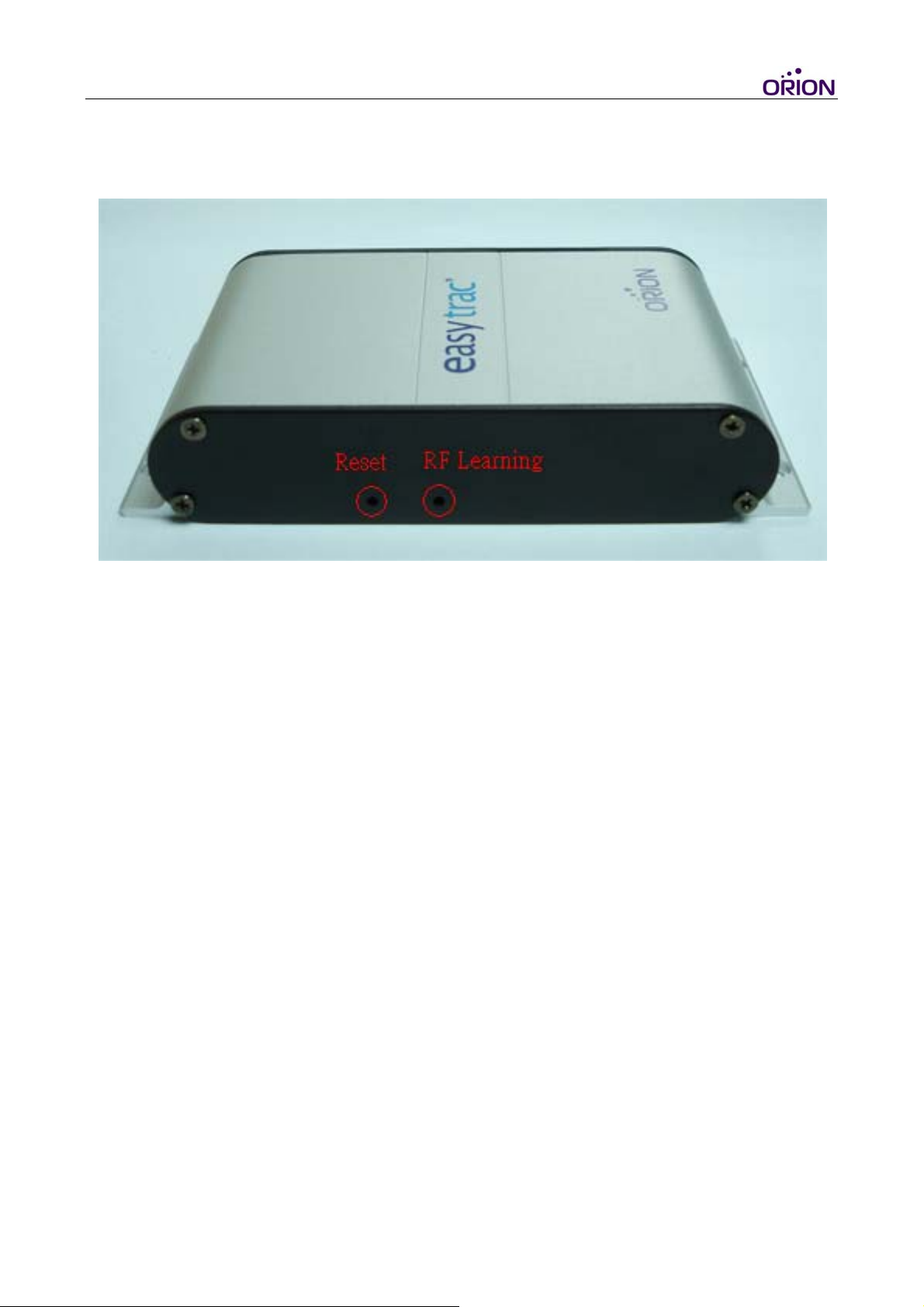
III. Rear panel:
1. RESET (Left tact switch button): System reboot
2. LEARNING (Right tact switch button): Remote controller learning
© 2007 ORION Technology LTD. All right reserved. 4/19
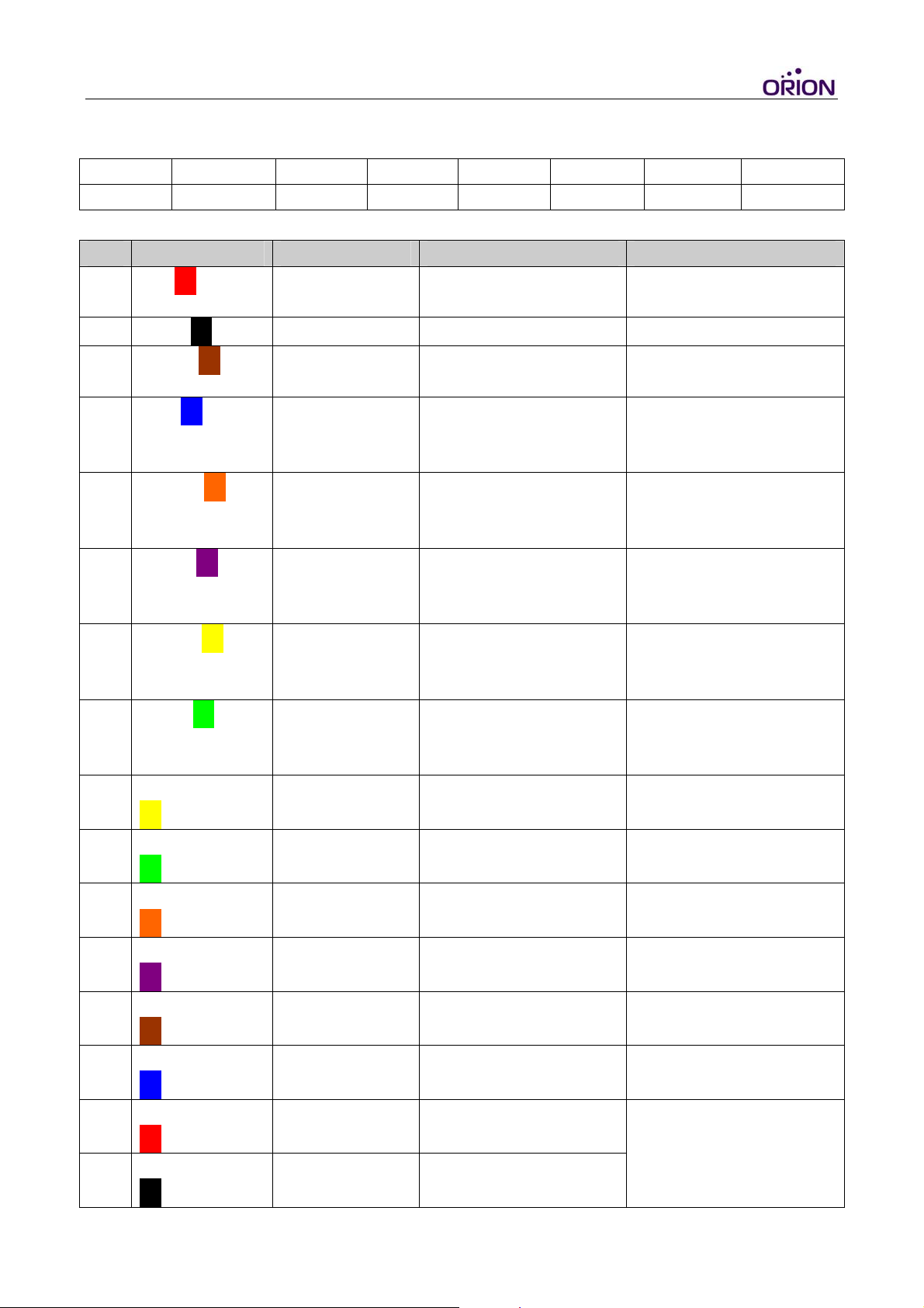
IV. V-16 Cable pin assignment:
V-16 Connector Pin Assignment
1-PWR 3-DI1 5-DI3 7-DI5 9-AI1 11-DO1 13-DO3 15-MICP
2-GND 4-DI2 6-DI4 8-DI6 10-AI2 12-DO2 14-DO4 16-MICN
V-16 Cable Pin Assignment
PIN Color Name Description Range
1
2
Red□
Black□
PWR Power supply input DC, 12V~24V +- 5%
Imax <= 2A
GND Ground 0V
3
4
5
6
7
8
9 Yellow-White
Brown□
Blue□
Orange□
Purple□
Yellow□
Green□
□-□
Digital Input 1 Reserved for Ignition
Digital Input 2 General purpose
Digital Input 3 General purpose
Digital Input 4 General purpose
Digital Input 5 General purpose
Digital Input 6 General purpose
Analog Input 1 General purpose
Input (ACC Input)
digital input (Positive
trigger)
digital input (Positive
trigger)
digital input (Positive
trigger)
digital input (Positive
trigger)
digital input (Positive
trigger)
analog input
High : 12V~24V
Low : 0V
High : 12V~24V
Low : 0V
High : 12V~24V
Low : 0V
High : 12V~24V
Low : 0V
High : 12V~24V
Low : 0V
High : 12V~24V
Low : 0V
Up to 24V DC/8bit
resolution
10 Green-White
□-□
11 Orange-White
□-□
12 Purple-White
□-□
13 Brown-White
□-□
14 Blue-White
□-□
15 Red-White
□-□
16 Black-White
□-□
© 2007 ORION Technology LTD. All right reserved. 5/19
Analog Input 2 General purpose
analog input
Digital Output 1 General purpose
digital output
Digital Output 2 General purpose
digital output
Digital Output 3 General purpose
digital output
Digital Output 4 General purpose
digital output
MIC-P Microphone +
MIC-N
Microphone
-
Up to 24V DC/8bit
resolution
500 mA max @
12V~24V
500 mA max @
12V~24V
500 mA max @
12V~24V
500 mA max @
12V~24V
R=50 kΩ differential
VImax = 20 mVpp

2. Configuration
I. Hardware and Software preparations
1. Remove the front panel of Easytrac and insert a SIM card with GPRS service
enabled. Lock the SIM card. (Caution: DO NOT remove the backup battery
from the Easytrac at anytime. Circuit short may occurred if the backup
battery is removed)
2. Re-cover the front panel.
3. Connect GPS antenna to Easytrac.
4. Connect GSM antenna to Easytrac.
5. Use a RS-232 cable (DB-9) to connect Easytrac to a PC COM port.
6. Open Hyper Terminal (or other terminal program) at Windows Start Menu
All Programs\Accessories\Communications\Hyper Terminal.
7. Add a new connection, input name ‘Easytrac’. Click “OK” and select the
COM Port for the Easytrac connection.
8. Set the Baud rate as 38,400bps and Flow control as none. Press “OK”.
9. Connect the V-16 cable to Easytrac.
© 2007 ORION Technology LTD. All right reserved. 6/19

10. Connect the V-16 cable power plug to the AC adapter and press the ‘ESC’
key of the PC within 3 second after AC adapter POWER ON and until the
text messages show on the Hyper Terminal screen. In doing so, Easytrac
boots on Configuration Mode.
11. Normally, the PWR LED is ON and the RF LED flashing constantly
which means the Easytrac is POWER ON and running. It shows as the
following on the Hyper Terminal.
EasyTrac Version : 0A04
- Build Date : Feb 27 2007
- Build Time : 07:40:20
- Serial Number : 1000000001
- IMEI : 352021002992709
Type "H" for the Debug Mode Commands Menu.
$>
12. If you don’t see the above messages on the Hyper Terminal, please check the
settings of Hyper Terminal and reconnect the power adapter or press the
RESET button on the Easytrac rear panel. Otherwise, please send an email to
support@oriontech.com.tw
for technical support.
II. Configuration step by step
1. Use ‘SCFG’ command to enter Main Setting Menu. All commands should be
upper case. (Wanning: ‘H’ command is for debug functions used by
advanced users. Misusing may cause system crash)
EasyTrac Version : 0A04
- Build Date : Feb 27 2007
- Build Time : 07:40:20
- Serial Number : 1000000001
- IMEI : 352021002992709
Type "H" for the Debug Mode Commands Menu.
$> <Press Enter>
Invalid Command
$> SCFG <Press Enter>
Main Setting Menu :
1. Basic Setting
2. GSM/GPRS Connection Setting
3. Remote Server Setting
© 2007 ORION Technology LTD. All right reserved. 7/19

E. Exit
Selection [1-3]? 1 <Press Enter>
2. Type ‘1’ in Main Setting Menu and press ‘Enter’ to configure basic settings.
Normally, no basic setting is needed to be changed at sample testing.
Basic Setting Menu :
1. EasyTrac Hardware : V5
2. EasyTrac Firmware : 0A04
3. EasyTrac Serial Number : 1000000001
4. EasyTrac UnitID : 1000000001 : [0000000000-4294967296]
5. EasyTrac User Password : 0000 <Password of Easytrac, default=0000>
6. EasyTrac GSM/GPRS Module Info :
SIEMEMS
MC55
03.03
7. EasyTrac GPS Module Info :
RoyalTek
REB-3310
1.3.5.56
8. EasyTrac Enable COM1 for DEBUG : YES : [NO|YES] <YES: Export
debugging messages to the Hyper Terminal via COM Port>
9. EasyTrac Enable LOG : YES : [NO|YES] <YES: Easytrac logs all system event in
the internal Flash memory for debugging. Eg. GPS fixed, GPS fail, GPRS online,
GPRS offline>
E. Exit
Selection [1-9]? E <Press Enter>
3. Type ‘2’ in Main Setting Menu to enter GPRS Connection Setting Menu
Main Setting Menu :
1. Basic Setting
2. GSM/GPRS Connection Setting
3. Remote Server Setting
E. Exit
Selection [1-3]? 2 <Press Enter>
Connection Setting Menu :
© 2007 ORION Technology LTD. All right reserved. 8/19

1. EasyTrac Switch Mode : GPRS : [AUTO|GPRS|SMS]
2. EasyTrac GPRS Reconnec : 16 : [16-65535]
3. EasyTrac SMS Duration : 180 : [180-65535]
4. SIM PIN1&2 Setting
SIM PIN1 :
SIM PIN2 :
5. GPRS Connection Setting
6. SMS Connection Setting
E. Exit
Selection [1-6]? 5 <Press Enter>
4. Set the GPRS settings item by item according to the information provided by
the carrier. The settings with * sign are required. After finishing setting, type
‘E’ to exit.
GPRS Connection Setting Menu :
*1. GPRS Dial Number : *99***1#
2. GPRS User Name :
3. GPRS Password :
*4. GPRS APN : mobiusone.com.tw <Access Point Name of GPRS service>
*5. GPRS Enable : ACCON : [STOP|START|ACCON] <STOP: Easytrac only
sends SYNC packet to the gateway server instead of GPS data; START: Easytrac
sends GPS data for continuous tracking as long as the Easytrac is POWER ON;
ACCON: Easytrac sends GPS data only if the Easytrac is POWER ON and the
ACC ON (Ignition ON) signal sent to Easytrac via Brown wire of V-16 cable. When
ACC OFF (Ignition OFF), Easytrac only sends SYNC packets to the gateway
server>
*6. GPRS Report Interval : 30 : [15-65535] <Time interval to send GPS data to the
gateway server. Default is 30 sec>
*7. GPRS SYNC Interval : 30 : [15-65535] <Time interval to send SYNC packet to
the gateway server. Default is 30 sec>
8. GPRS Filter : NO : [YES|NO] <YES: Easytrac only sends valid GPS data; NO:
Easytrac sends valid and invalid GPS data to the gateway server.>
9. GPRS DNS : 168.95.1.1 <DNS Server IP address of the carrier>
E. Exit
Selection [1-9]? E <Press Enter>
© 2007 ORION Technology LTD. All right reserved. 9/19

5. Return to Connection Setting Menu and type ‘E’ to return to Main Setting
Menu..
Connection Setting Menu :
1. EasyTrac Switch Mode : GPRS : [AUTO|GPRS|SMS]
2. EasyTrac GPRS Reconnec : 16 : [16-65535]
3. EasyTrac SMS Duration : 180 : [180-65535]
4. SIM PIN1&2 Setting
SIM PIN1 :
SIM PIN2 :
5. GPRS Connection Setting
6. SMS Connection Setting
E. Exit
Selection [1-6]? E <Press Enter>
6. Type ‘3’ in Main Setting Menu to enter Remote Server Setting Menu.
Main Setting Menu :
1. Basic Setting
2. GSM/GPRS Connection Setting
3. Remote Server Setting
E. Exit
Selection [1-3]? 3 <Press Enter>
7. Set the Remote Server (Gateway Server) settings. The settings with * sign
are required. Type ‘1’ to change settings. When it is done, type ‘E’ to exit to
the previous menu.
Remote Server Setting Menu :
1. Remote Primary Server
*Main Server IP : 10.1.99.179 <The Gateway Server IP address which running
tcpserver.exe program to communicate with Easytrac and receive GPS data>
*Main Server Port : 9998 : [0-65535] <Port Number corresponds to the setting
of tcpserver.exe program to receive SYNC packet and GPS data. Default is 9998>
E. Exit
Selection [1]? E <Press Enter>
© 2007 ORION Technology LTD. All right reserved. 10/19

8. When finishing all settings. Type ‘E’ to exit Main Setting Menu and save the
changes to the Flash memory of the Easytrac.
Main Setting Menu :
1. Basic Setting
2. GSM/GPRS Connection Setting
3. Remote Server Setting
E. Exit
Selection [1-3]? E <Press Enter>
9. Type ‘YES’ to apply all setting changes.
Write to the External FLASH [YES|NO]? YES <Press Enter>
FLASH Sector Erase Start
Sector Number : 0x03 - Sector Address : 0x00030000
.
FLASH Sector Erase Done
Writing 0x000005DC Bytes
FLASH Reset Done
Done.
10. Make sure GPS antenna, GSM antenna, RS-232 cable, V-16 cable are all
secured to Easytrac main unit before Press RESET button on the Easytrac
rear panel to reboot system.
III. Running on normal mode
1. Easytrac reboots on normal mode. Normally, PWR LED is ON and the
RF LED flashing constantly which means the Easytrac is POWER ON and
running. About 30 sec later, GSM LED starts flashing then keeps ON
which means GPRS session Online. Also GPS LED starts flashing for
searching GPS signal then keeps ON which means GPS fixed.
PWR
GSM
© 2007 ORION Technology LTD. All right reserved. 11/19
ON
ON
RF
GPS
Flash
ON

2. Note: Before running Easytrac on normal mode. A Gateway Server which
runs the tcpserver.exe with a public IP address must be ready. The
tcpserver.exe is basically a TCP socket listener which building the socket
sessions with multiple trackers via TCP/IP over GPRS and internet. Please
refer to About TcpServer.txt , About Demo.txt and ORION gateway server
API.pdf for more information. To verify your Gateway Server working well,
you may use AVL simulator program to send simulated SYNC packets and
GPS data to the Gateway Server. Please refer to AVL Simulator Manual.pdf
for more information.
3. If the Gateway Server is not ready, the GSM LED will keep flashing.
4. If the Easytrac and the Gateway Server are working well. It shows as the
following on the Hyper Terminal.
EasyTrac Version : 0A04
- Build Date : Mar 01 2007
- Build Time : 13:35:03
- Serial Number : 2000000988
- IMEI : 352021002966604
Init. Profiles...
Write - 0009 - AT
Waiting...
Waiting...
Response - SYSSTART
Waiting...
Write - 0008 - AT
Response - OK
Write - 0009 - AT+IPR=38400
Response - OK
Write - 0009 - ATE0
Response - OK
Write - 0009 - AT+CREG=2
Response - OK
Write - 0009 - AT+COPS=0
Response - OK
Write - 0009 - AT&W
Response - OK
© 2007 ORION Technology LTD. All right reserved. 12/19

Write - 0009 - AT+GSN
Response - 352021002966604
Response - OK
IMEI : 352021002966604
Write - 0009 - AT^SICS=0,conType,GPRS0
Response - OK
Write - 0009 - AT^SICS=0,dns1,"168.95.1.1"
Response - OK
Write - 0009 - AT^SICS=0,passwd,""
Response - OK
Write - 0009 - AT^SICS=0,apn,"mobiusone.com.tw"
Response - OK
Write - 0009 - AT^SISS=0,srvType,socket
Response - OK
Write - 0009 - AT^SISS=0,conId,0
Response - OK
Write - 0009 - AT^SISS=0,address,"socktcp://10.1.99.179:9998"
Response - OK
Write - 0009 - AT+CSMS=0
Response - +CSMS: 1,1,1
Response - OK
Write - 0009 - AT+CMGF=0
Response - OK
Init. Profiles Done <Initiating GPRS Profiles is done>
Write - 0011 - AT^SISC=0
Response - OK
GPRS Connection is Closed.
Write - 000F - AT^SISO=0
Waiting...
Waiting...
Waiting...
Waiting...
Waiting...
Response - OK
Waiting...
Response - ^SISW: 0, 1
GPRS Connection is Opened. <Easytrac attaches to GPRS service>
© 2007 ORION Technology LTD. All right reserved. 13/19

SYNC Command:
Write - 0009 - AT^SISW= 0, 8
Response - ^SISW: 0, 8
Write - 0009 - C8 CA 00 00 7A 94 35 77 0D 0A <Send SYNC to Gateway Server>
Response - OK
Response - ^SISW: 0, 1
Write - 0009 - AT^SISR=0, 128
Response - ^SISR: 0, 8
Response - OK
Received Command : C8 CA 00 53 49 53 52 3D <Get SYNC Ack from Gateway
Server>
Write - 0009 - AT^SISR=0, 128
Response - ^SISR: 0, 34
Response - $SetTimeStamp,1724,0000,226171453&
Response - OK
Received Command : $SetTimeStamp,1724,0000,226171453& <Get TimeStamp
from Gateway Server>
Server Request Command
00 : SetTimeStamp
01 : 1724
02 : 0000
03 : 226171453
FLASH Sector Erase Start
Sector Number : 0x01 - Sector Address : 0x00010000
FLASH Sector Erase Done
Writing 0x000005DC Bytes
FLASH Reset Done
Done.
Time Stamp = 0D7B1A3E <Set TimeStamp to Easytrac>
Response Command
$SetTimeStamp,1724,OK&
Write - 0009 - AT^SISW= 0, 24
Response - ^SISW: 0, 24
Write - 0009 - $SetTimeStamp,1724,OK& <Send SetTimeStamp OK to Gateway
Server>
Response - OK
Response - ^SISW: 0, 1
© 2007 ORION Technology LTD. All right reserved. 14/19

Counter : 0001
Time Stamp : 0D7B1A3E
Type : U
Resend : N
Data : SetTimeStamp,1724,OK
GPRS Track:
Write - 0009 - AT^SISW= 0, 90
Response - ^SISW: 0, 90
Write - 0009 -
$evtGPRSTrack,2000000122,110905000017.044,V,00000.0000,E,0000.000
0,N,00,13,0.00,0,0,0,2& <Send GPS data to Gateway Server>
Response - OK
Response - ^SISW: 0, 1
5. If the Demo.exe and Gateway Server are working well, it shows the SYNC
packet and GPS data on the Demo window, too. You can compare them to
those showing on the Hyper Terminal window.
6. To parse the GPS data string, please refer to the command 2.1
ActGPRSTrack of ORION Protocol.pdf.
7. If the Easytac can not connect to the Gateway Server and send GPS data,
please recheck the settings. Otherwise please send an email to
support@oriontech.com.tw
for technical support.
© 2007 ORION Technology LTD. All right reserved. 15/19

IV. Test protocol commands via RS-232 connection
1. You may test commands of ORION Protocol.pdf by RS-232 connection
instead of GPRS connection. Type ‘H’ to enter Debug Mode Command
Menu. Type the protocol commands after the prompt and check the tracker
responses. Please refer to ORION Protocol.pdf for more command details.
EasyTrac Version : 0A04
- Build Date : Feb 27 2007
- Build Time : 07:40:20
- Serial Number : 1000000001
- IMEI : 352021002992709
Type "H" for the Debug Mode Commands Menu.
$> <Press Enter>
Invalid Command
$>H <Press Enter>
EasyTrac Debug Mode Command Menu:
A2D - Get the Current Analog Inputs.
DCFG - Firmware Default Configuration.
DI - Show the Current Digital Input's Status.
DO[1|2|3|4] - Toggle the Specified DOx.
EXIT - Return to the Normal Mode.
LED[1|2|3|4] - Toggle the Specified LEDx.
LOG - Display the Logged Records.
LOG_RESET - Reset the Logged Records.
IGPRS - Init. GPRS Profiles.
ISMS - Init. SMS Profiles.
MA2D - Monitor the Current A2D Status.
MDI - Monitor the Current DI Status.
MGPRS - Monitor the Current GPRS's Status.
MINT - Monitor the Current INTs' Status.
MRTC - Monitor the Current RTC Status.
FCFG - FLASH Saved Configuration.
FLASH_RESET - Reset Whole FLASH Chip to 0x00.
RD Address - Read Data from the Address Address.
RTC - Get the Current RTC Status.
RUN - Return to the Running Mode.
SCFG - Set Configuration.
SETMODE DOWNLOAD - Set to the Download Mode.
SETVL [GPRS|GPS] - Set Virtual Link to GPRS or GPS Mode.
SRAM_FLASH - Test the External SRAM and FLASH.
© 2007 ORION Technology LTD. All right reserved. 16/19

WR Address Data - Write Data to the Address.
WTD - Watchdog Reset.
$...& - Protocol Commands Test. <Start by $ sign, End by & sign>
$>$GetUnitID,1234,0000& <Press Enter>
Server Request Command
00 : GetUnitID
01 : 1234
02 : 0000
Response Command
$GetUnitID,1234,1000000001&
$>
V. Get the system logs via RS-232 connection for advanced debugging
1. The GPS tracker behaviors may be various in different areas because of the
GSM coverage and GPRS service settings. If the GPRS connection of a
tracker is not stable, you may retrieve the system logs from the tracker to
verify them and figure out the reason causing the problems. Type ‘H’ to enter
Debug Mode Command Menu. Type ‘LOG’ after the prompt to retrieve the
system logs and check the system logs with ORION’s engineers. This feature
helps us to fine tune the firmware to improve the tracker’s performance in
different countries. For more information, please contact
support@oriontech.com.tw
EasyTrac Version : 0A04
- Build Date : Feb 27 2007
- Build Time : 07:40:20
- Serial Number : 1000000001
- IMEI : 352021002992709
Type "H" for the Debug Mode Commands Menu.
for more information.
$> <Press Enter>
Invalid Command
$>H <Press Enter>
EasyTrac Debug Mode Command Menu:
A2D - Get the Current Analog Inputs.
© 2007 ORION Technology LTD. All right reserved. 17/19

DCFG - Firmware Default Configuration.
DI - Show the Current Digital Input's Status.
DO[1|2|3|4] - Toggle the Specified DOx.
EXIT - Return to the Normal Mode.
LED[1|2|3|4] - Toggle the Specified LEDx.
LOG - Display the Logged Records. <Get system logs from the tracker>
LOG_RESET - Reset the Logged Records.
IGPRS - Init. GPRS Profiles.
ISMS - Init. SMS Profiles.
MA2D - Monitor the Current A2D Status.
MDI - Monitor the Current DI Status.
MGPRS - Monitor the Current GPRS's Status.
MINT - Monitor the Current INTs' Status.
MRTC - Monitor the Current RTC Status.
FCFG - FLASH Saved Configuration.
FLASH_RESET - Reset Whole FLASH Chip to 0x00.
RD Address - Read Data from the Address Address.
RTC - Get the Current RTC Status.
RUN - Return to the Running Mode.
SCFG - Set Configuration.
SETMODE DOWNLOAD - Set to the Download Mode.
SETVL [GPRS|GPS] - Set Virtual Link to GPRS or GPS Mode.
SRAM_FLASH - Test the External SRAM and FLASH.
WR Address Data - Write Data to the Address.
WTD - Watchdog Reset.
$...& - Protocol Commands Test.
$>LOG <Press Enter>
FLASH Reset Done
Display - First User Sector Found : 08
Display - User Sector : 08
*******************
Time Stamp : 0D771C7E
Type : U
Resend : N
Data : SetTimeStamp,1644,OK
Time Stamp : 0D771C80
Type : U
Resend : N
Data : SetTimeStamp,1644,OK
Time Stamp : 0D771C9C
Type : U
© 2007 ORION Technology LTD. All right reserved. 18/19

Resend : N
Data :
evtGPRSTrack,2000000963,270207084246.000,A,12131.2661,E,2502.8625,N,08,30
,178.93,0.00,0,0,126
Time Stamp : 0D771CBA
Type : U
Resend : N
Data :
evtGPRSTrack,2000000963,270207084316.000,A,12131.2572,E,2502.8579,N,08,31
,178.93,0.00,0,0,126
Time Stamp : 0D771CD8
Type : U
Resend : N
Data :
evtGPRSTrack,2000000963,270207084346.000,A,12131.2609,E,2502.8542,N,09,30
,178.93,0.00,0,0,126
FCC warning statement
This model complies with part 15/22H/24E
subject to the condition that this device does not cause harmful interference.
This device complies with Part 15 of the FCC Rules. Operation is subject to
the following two conditions:(1) this device may not cause harmful
interference and (2) this device must accept any interference received,
including interference that may cause undesired operation.
of the FCC Rules. Operation is
TEL: 886-2-2521-2610
http://
Email:
www.oriontech.com.tw
support@oriontech.com.tw
© 2007 ORION Technology LTD. All right reserved. 19/19
 Loading...