

Orion Optics Europa 114, Europa 150, Europa 200, Europa 200 f4 SCH, Europa 250 Instruction Manual
EUROPA
INSTRUCTIO}IS
Instruclion
Manual
Europa
il4
Europa
150
Europa 2OO
Ewopa 25O
Europa 2O0
f4 SCH
Orion
Optics
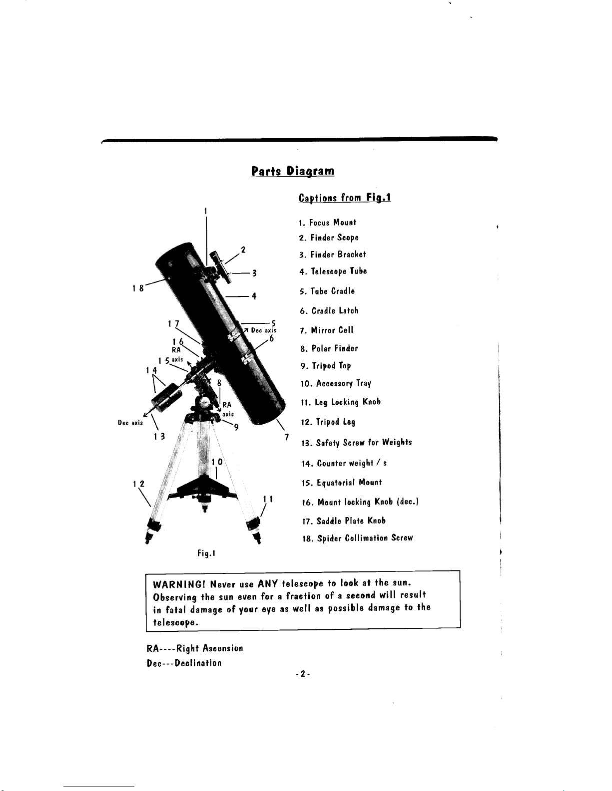
Parts
Diagram
I
J
1
Capiions
from
Fig.l
l. Focus
Mount
2. Finder
ScoPe
3. Finder
Bracket
4.
TelescoPe
Tube
5. Tube
Cradle
6. Cradle
Latch
7.
Mirror
Cell
8.
Polar
Finder
9.
Tripod
ToP
10. Accessory
TraY
ll. Leg
Locking
Knob
12.
Tripod
leg
13.
Safety
Screw
for
Weights
14.
Counter
weight
/ s
15.
Equatorial
Mount
16.
Mount
locking
Knob
(dec.)
17. Saddle
Plate
Knob
18.
Spider
Collimation
Screw
F ig.l
I
I
I
RA----Righi
Ascension
Dec-
--
Dec
! i nation
WARNING!
Never
Observing
the
sun
in
fataf
damage
ot
ie I escope
.
telescope
to
look
at
fhe
sun-
a fraclion
of a
second
will
result
as
wef l
as
possible
damage
to
fhe
use
even
you r
ANY
for
eve
-2-

Parts
Diagram
Pre
assembly
notes
Telescope
assembly
Legs
Accessory
tray
Equatorial
mount
Telescope
attachment
Positioning
of
the telescope
Assembling
the finderscope
Balancing
the
telescope
Alignmeni
of the
finderscope
Your
firsi
observaiion
Using your
Polar
finder
How
to
use ihe
setting
circles
Collimation
Seeing
conditions
Trouble
shooting
Spec
ifications
Gem
Drives
N otes
2
4
5
5
5
6
7
8
8
8
9
t0
l0
l2
l3
t5
t5
t6
l7
l7
E--
-3-

PLEASE
READ
THIS
LEAFLET
THOROUGHLY,
PRIOR
TO
ASSEMBLY
OR
USAGE'
Pre Assembly
Notes
Your
tetescope
assembly
will
be
easily
accomplished
providing
the
following
instructions
are
carried
our
in
the
order
they
are
given-
lf
they
are
carried
out
incorreclly
or
ihe
lelescope
is
not
assembled
in
the
order
prescribed,
considerable
damage
could
be
caused
io
the
instrument'
All
the
models
in
the
Europa
range
are
assembled
in
the
same
manner'
The
only
modification
is
the
slightly
different
Europa
2OO
14
Schmidt
Newionian.
This
model
has
a stightly
different
meihod
of
collimation
compared
to
the
olher
telescoPes.
This
will
be
dealt
wirh
in
a separale
section
within'Collimation"
All
fhrough
the
insiructions
manua!
pictures
and
illustrations
of
the
Europa
2OO
are
shown,
apart
from
obuious
differences
in
size
of
the
25omm
and
2OOmmf4sch,
the
altachment
method
of
all
the
parts
are
in the
same
mannef.
when
checking
all
the
constituent
parts
of
the
ielescope
prior
to
assembly'
plr.*,
ensure-no
damage
has
occrtrred
in
transil.
No
claim
for
damage
or
missing
items
can
be
a-ccepted
if
made
more
than 48
hours
afler
receipt
or
collection,
unless
agreed
by
Orion
Optics'
Themosiimportantandaccurateparisofthetelescopearethetwo
mirrors
within
the
tube.
These
ate
coaled
with
two
microscopically
thin
layers
of
aluminium
which
are
over-coated
with
quartz'
lo
give
the
alu-
miniumaddedprotection.TheseoPtica!surfacesarequiiedelicaieand
MUsTNoTBEToUcHEDWITHFINcERSoRANYUNSUITABLE
CLEANING
PRODUCT.
Unfortunately
we
cannot
eccepl
responsibility
for
any
optical
surface
which
has
been
cleaned
incorrectly'
WARNING!
Never
Observing
ihe
sun
in
fatal
damage
of
telescoPe.
use
ANY
telescoPe
even
for
a
fraciion
your
eye
as
well
as
to
look
ai
the
sun.
of
a
second
will
resu
lt
possible
damage
to
the
Ietescope
essemUh
The
following
notes
apply to all
models,
any small
difference in
assembly will
be
indicated
where
appropriate.
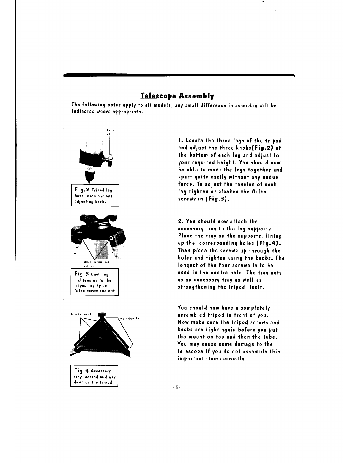
Knobs
l. Locate the
three legs
of the fripod
and
adjusl fhe
three knobs(Fig.2)
at
the
botiom of each
leg and adjusl
to
your
required
height.
You should
now
be able
to move the
legs together
and
apart quile
easily without
any
undue
force.
To adjust the
tension of
each
leg
tighten or
slacken fhe
Allen
screws in
(
Fig.3).
2.
You shou ld
now attach the
accessory iray
to the leg
supports.
Place
the tray on the
supports,
lining
up the corresponding
holes
(Fig.al.
Then
place
lhe screws
up through the
holes and tighten
using
the knobs.
The
longest
of the four screws
is to be
used
in fhe
cenlre hole.
The tray acts
as an accessory
lray as
well as
sfrengthening
the
tripod itself.
You should now
have a completely
assembled
tripod
in front of
you.
Now
make sure fhe
tripod screws
and
knobs
are tight
again before you
puf
the mounl
on fop and
then the tube.
You
may cause
some
damage
to
the
telescope if
you
do
nol assemble
lhis
importanf item
correclly.
Fig.4
Accessory
lray
localed nid
way
down on the
tripod.
Allen scrcrr
and
nul
13
Fig.3 Each
tes
tighiens
up to the
tripod
top by
an
Allen screr,v and
nut.
Fig.2
Tripod leg
base, each
has one
adjusiing
knob.
Tray lnobs
r6
-5
 Loading...