

ORION Images 17RTCLD, 19RTCLD, 19RTCLDSR Installation And User Manual
Installation and User's Guide
All contents of this document may change without prior notice, and actual product appearance may differ from that depicted herein
ULTRA BRIGHT MONITOR SERIES
(17~19 inches)
http://www.orionimages.com
2
Installation and User's Guide
1. SAFETY INSTRUCTION
Follow this safety instruction to use the monitor properly and prevent the damages.
Keep this user’s guide book for later use.
This safety instruction has “Warning” & “Caution” as below
Warning -
If the user does not follow this instruction,
it may cause the serious damage to the user.
Caution -
If the user does not follow this instruction, it may cause the slight
damage to the user or cause some damages to the monitor.
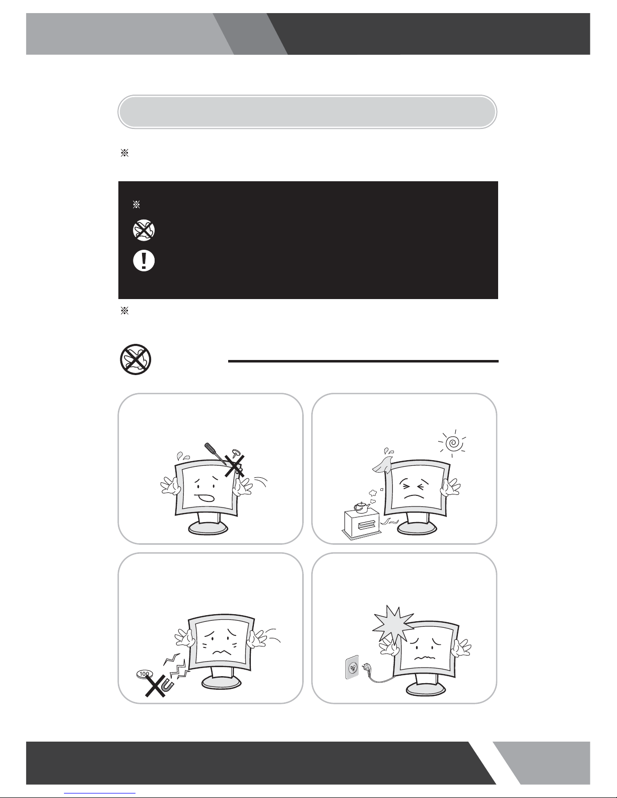
Warning
Keep away the monitor from the
direct sunlight and a heating appliance.
Never push objects of any kind into
this product as they may result in
a risk of fire or electric shock.
Connect the power code to the wall
outlet tightly. If the power code or plug
are defective and the wall outlet is not
tight, please do not use them.
Never remove the back over and
touch the inside of the monitor.
If you need a service, please
contact the service center.

3
Installation and User's Guide
Warning
Do not install this monitor on the outside
and near water. If may cause damage to
the product, electric shock and fire.
For cleaning do not use liquid cleaners.
Never touch the power plug with wet-hands.
When lightning and thundering, unplug the
monitor from the wall outlet and never touch
it.
When smoking and noising from the monitor,
unplug the product from the wall outlet and
contact a service center.
Unplug this product from the wall outlet, when
It does not operate for a long time.
W
W
A
A
R
RNN
IIN
N
G
G
:
:
How to fix
Do not open this product as it contains high voltage inside.
It may create an electric shock.
It the user disassembles and remove the back cover, it does not make sure
to make up for the damages and do a service and exchange the monitor.
4
Installation and User's Guide
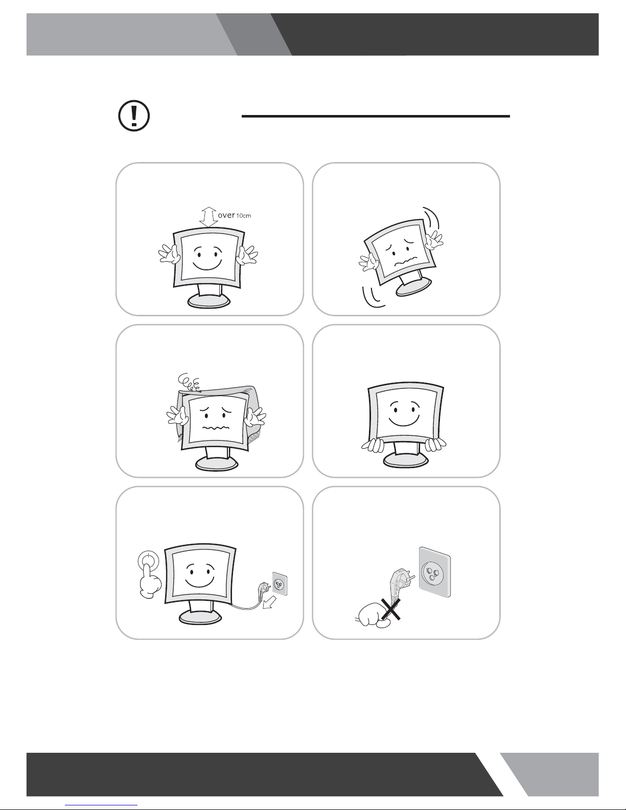
Cautions
Install this monitor some distance
From the wall and do not install unless
Proper ventilation is provided.
Place this product on a stable place.
If not, it may fall, causing serious
Damages to the monitor and people.
The openings must not be blocked by
curtain, rug or other similar surface.
Before carrying the monitor, tum it off and
Unplug the signal cables and the power code
From the wall outlet.
When carrying this monitor, be careful
not to damage the panel and drop it
It may cause some trouble.
Take the power plug out from the wall
outlet.
Do not pull the cable. It may snap the innerwires and cause overheating and fire.
5
Installation and User's Guide
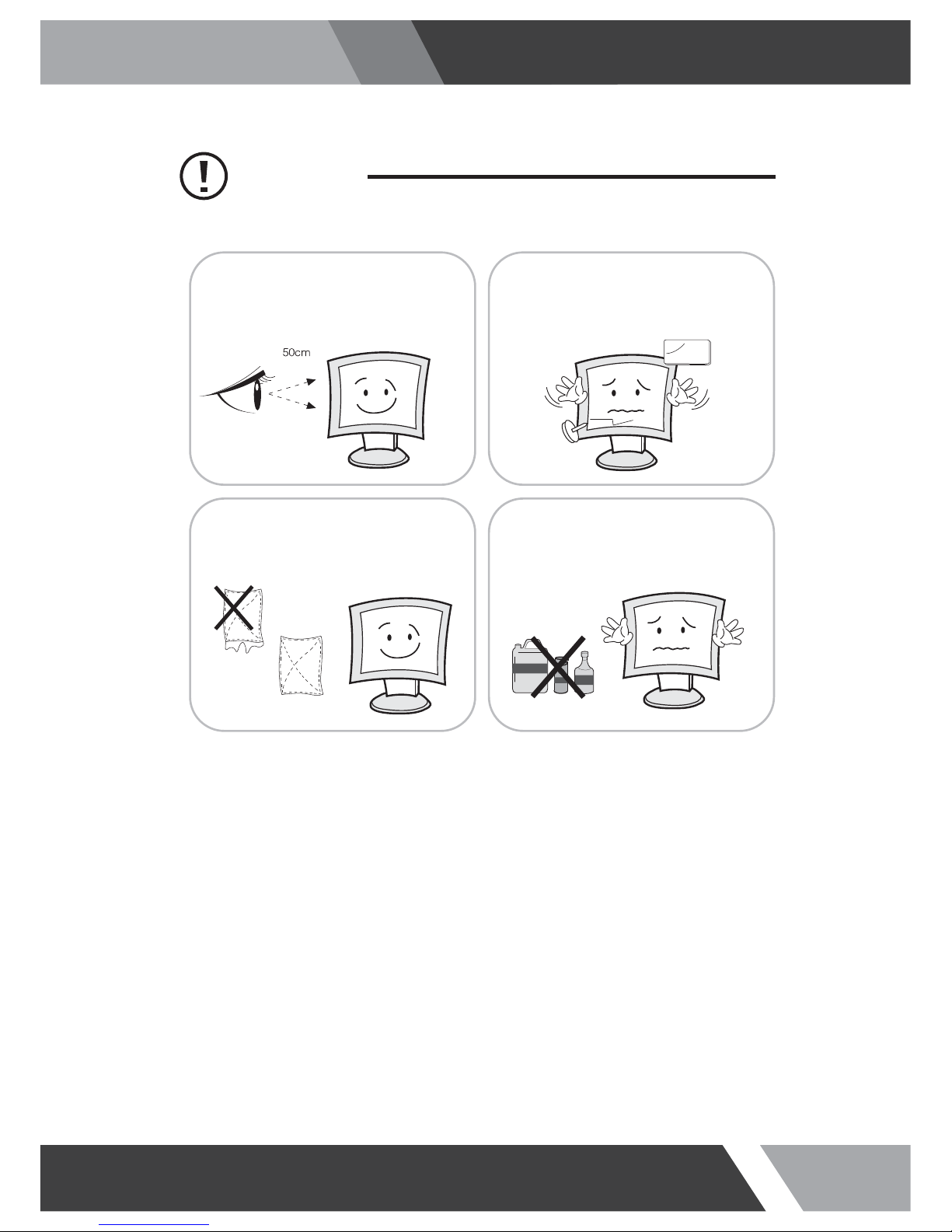
Cautions
Install this monitor about 50cm far from
the eyes and an angle of 0~15 degrees
below eyes. Too close installation may
cause having weak sight.
Do not press the LCD panel with hands or
the sharpened material hardly.
Do not use the chemical liquid for cleaning.
It may cause fading and breakage.
For cleaning, unplug the monitor from the
Wall outlet. Do net use the liquid cloth.
Use the soft cloth.
6
Installation and User's Guide
This equipment has been tested and found to comply with the limits for a Class A digital device, pursuant
to Part 15 of the FCC Rules. These limits are designed to provide reasonable protection against harmful
interference in a residential installation. This equipment generates, uses and can radiate radio frequency
energy and, if not installed and used in accordance with the instructions, may cause harmful
interference to radio communications. However, there is no guarantee that interfe
renc
e will not occur in a
particular installation. If this equipment does cause harmful interference to radio or television reception
which can be determined by turning the equipment off and on, the user is encouraged to try to correct
the interference by one or more of the following measures.
N
TE
Reorient or relocate the receiving antenna.
Increase the separation between the equipment and receiver.
Connect the equipment into an outlet on a circuit different from that to which the receiver
is connected.
Consult the dealer or an experienced radio, TV technician for help.
Only shielded interface cable should be used.
Finally, any changes or modifications to the equipment by the user not expressly approved by the
grantee or manufacturer could void the users authority to operate such equipment.
DOC COMPLIANCE NOTICE
This digital apparatus does not exceed the Class A limits for radio noise emissions from digital apparatus
set out in the radio interference re
g
ulation of Canadian Department of communications.
2. FCC RF INTERFERENCE STATEMENT

7
Installation and User's Guide
2
1. SAFETY INSTRUCTION
1-1 Warning
1-2 Caution
6
2. FCC STATEMENT
3-1 Parts
3-2 How to Install
32
7. TROUBLESHOOTING
6. LIMITED WARRANTY
8
3. INSTALLATION
4-1 Mode Setting
4-2 Menu Setting (VIDEO, S-VIDEO, COMPONENT Mode)
4-3 Menu Setting (VGA Mode)
4-4 Menu Setting (DVI, HDMI Mode)
12
4. OSD MENU SETTING
33
5. FEATURES
34
TABLE OF CONTENTS
8
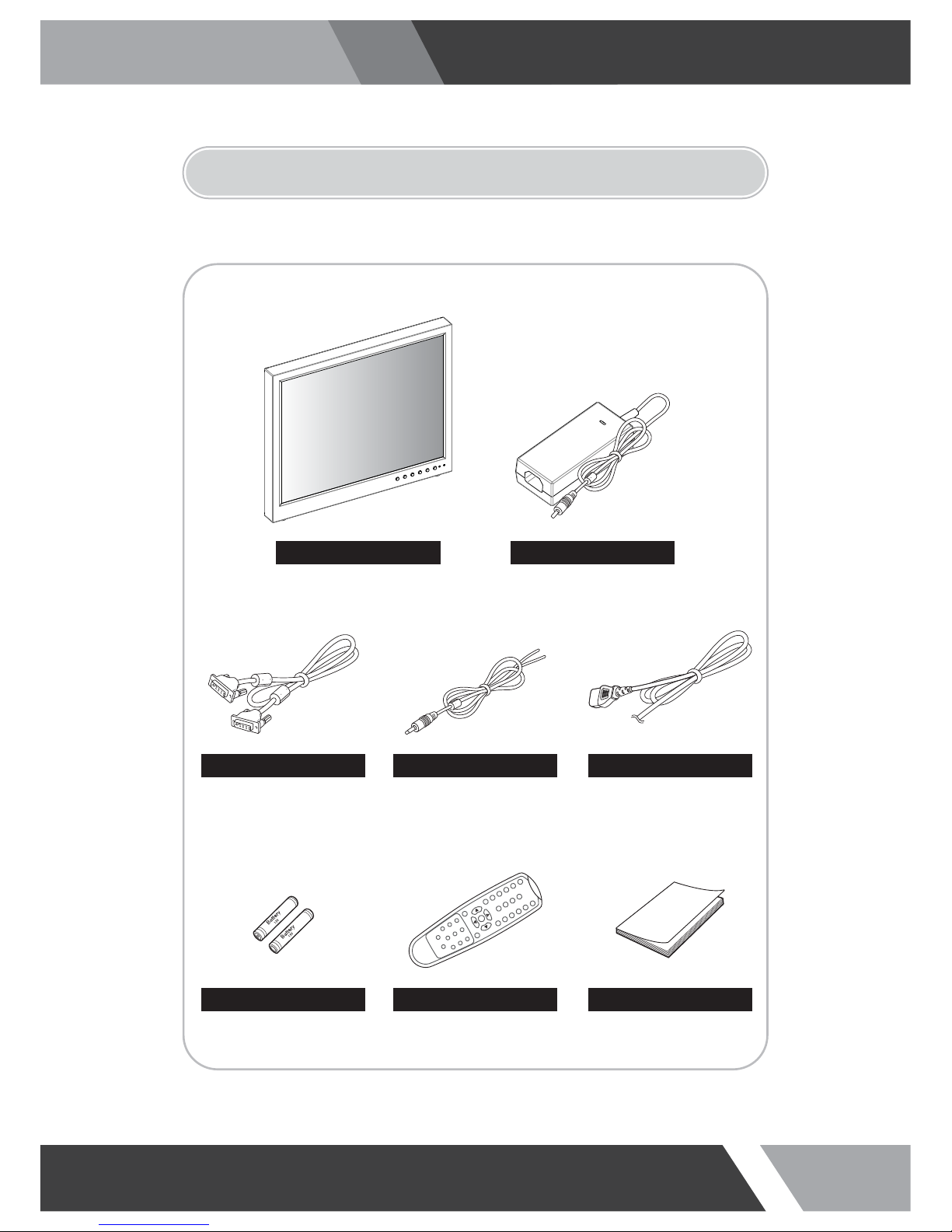
Installation and User's Guide
3. INSTALLATION
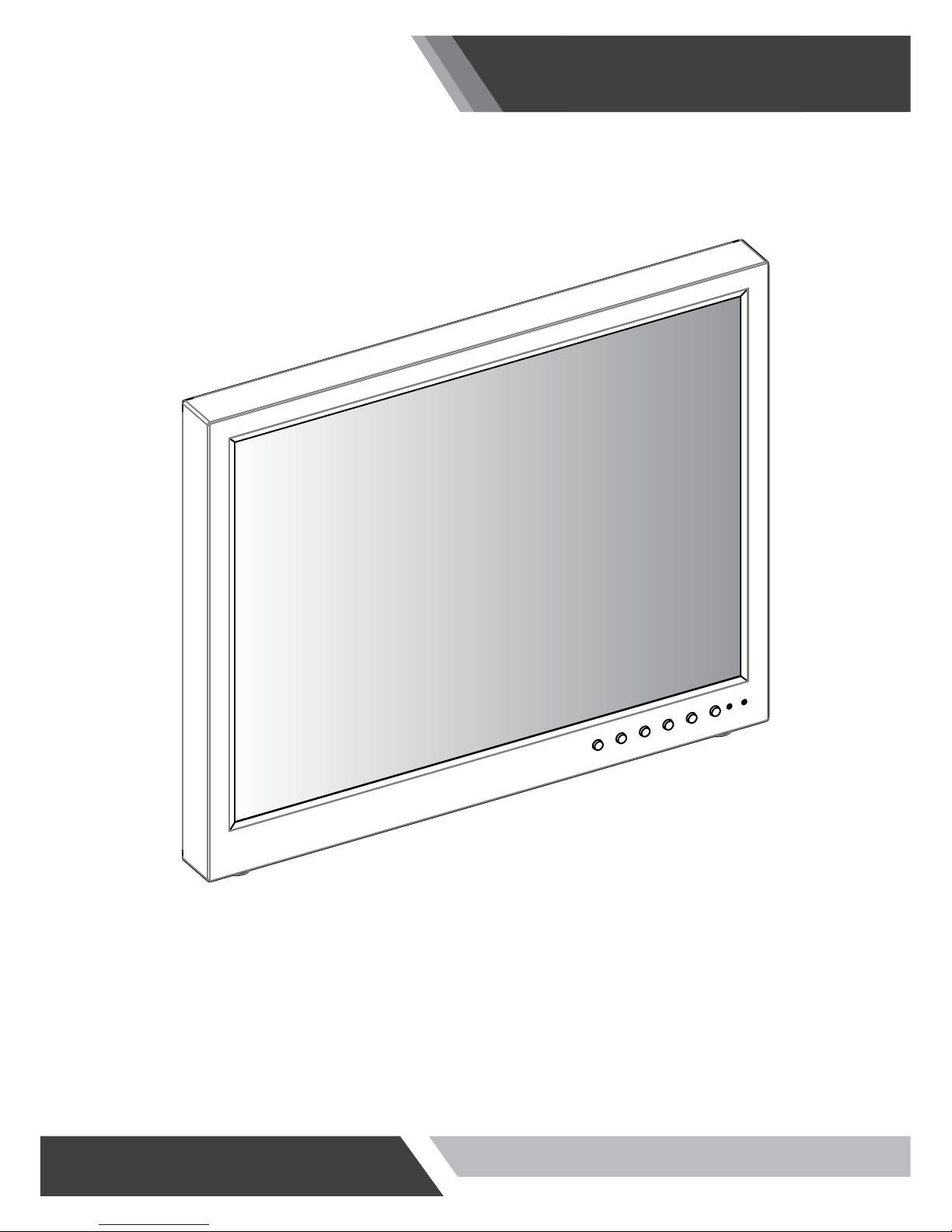
3-1 Parts
LCD Monitor
VGA Cable Trigger Cable Power Cable
Remote Controller
Battery User Manual
Adapter
* The Adapter might be attached to the back of product
9
Installation and User's Guide
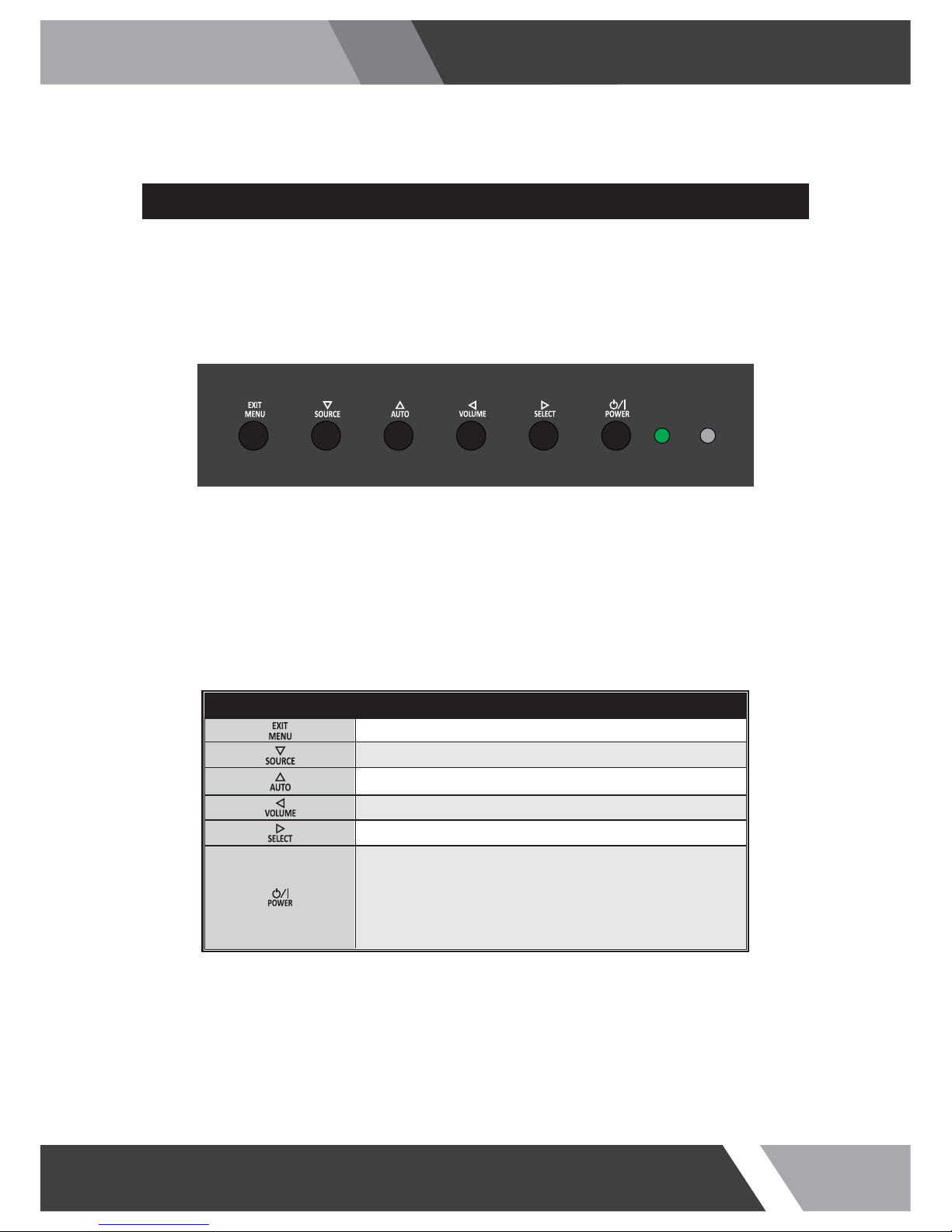
3-2 How to Install
SHORT KEY FUNCTION
KEY BUTTON
OSD Key Function
Activates and exit the OSD
Select input source, and select the OSD menu
Move the OSD menu and auto adjustment of RGB source
Decrease the level of volume and move the previous menu
Increase the level of volume and select rhe OSD menu
Turns the power ON or OFF.There will be a few seconds
delay before the display appears.The power LED (next to the
power switch) lights with green when the power is turned ON.
The power is turned o ff by pressing the power switch again
and the power LED goes red.
10
Installation and User's Guide
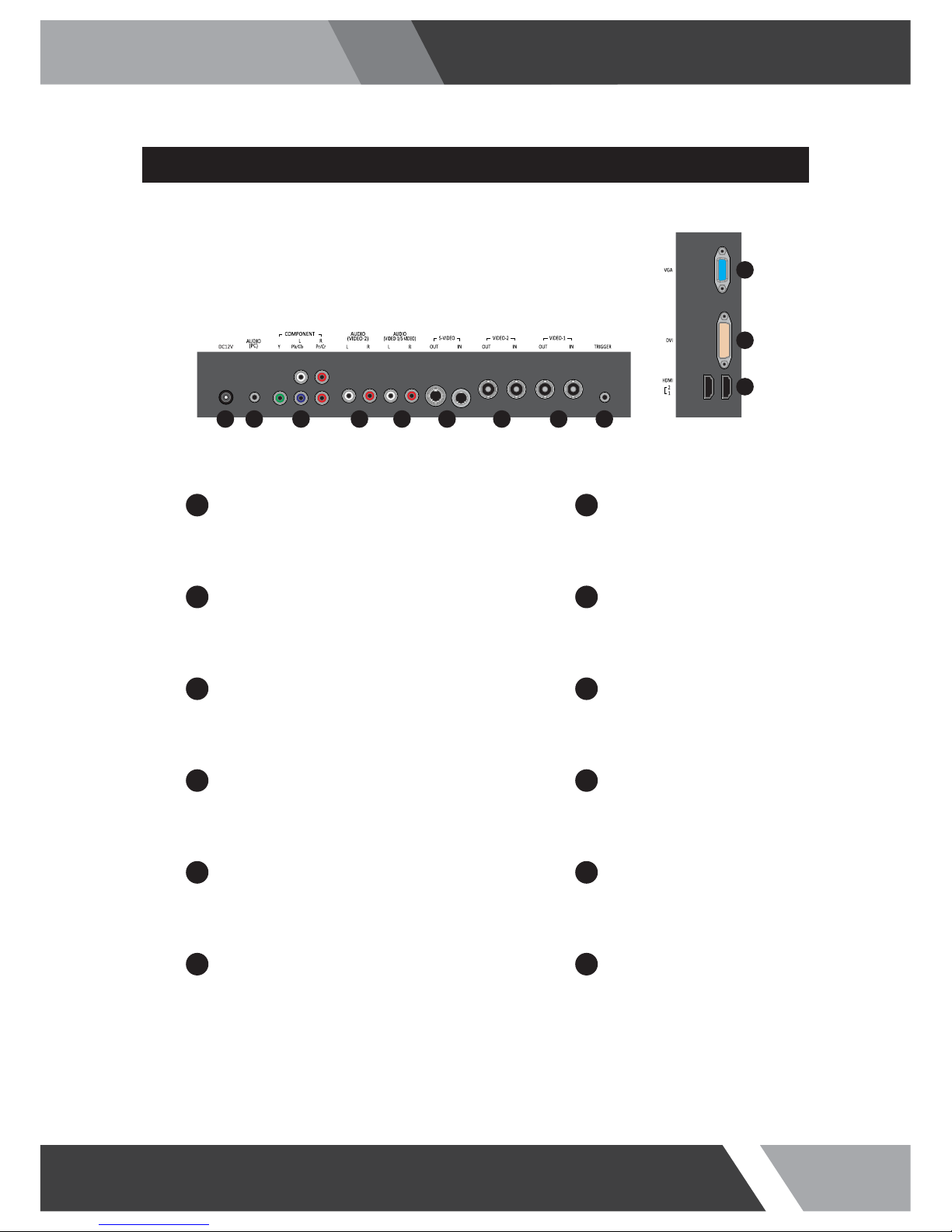
CONNECTION
DC12V
1
VIDEO-2 IN / OUT
DC adapter input VIDEO-2 signal input / looping out
7
AUDIO (PC)
2
VIDEO-1 IN / OUT
Stereo audio input for VGA VIDEO-1 signal input / looping out
8
COMPONENT
3
TRIGGER
COMPONENT (Y/Pb/Pr) signal & stereo audio input TRIGGER signal input
9
AUDIO (VIDEO-2)
4
HDMI
Stereo audio input for VIDEO-2 HDMI signal 1 / 2 input
10
AUDIO (VIDEO-1 / S-VIDEO)
5
DVI
Stereo audio input for VIDEO-1 or S-VIDEO DVI signal input
11
S-VIDEO IN / OUT
6
VGA
S-VIDEO signal input / looping out VGA (PC RGB) signal input
12
10
11
12
1 2 3 4 5 6 7 8 9
11
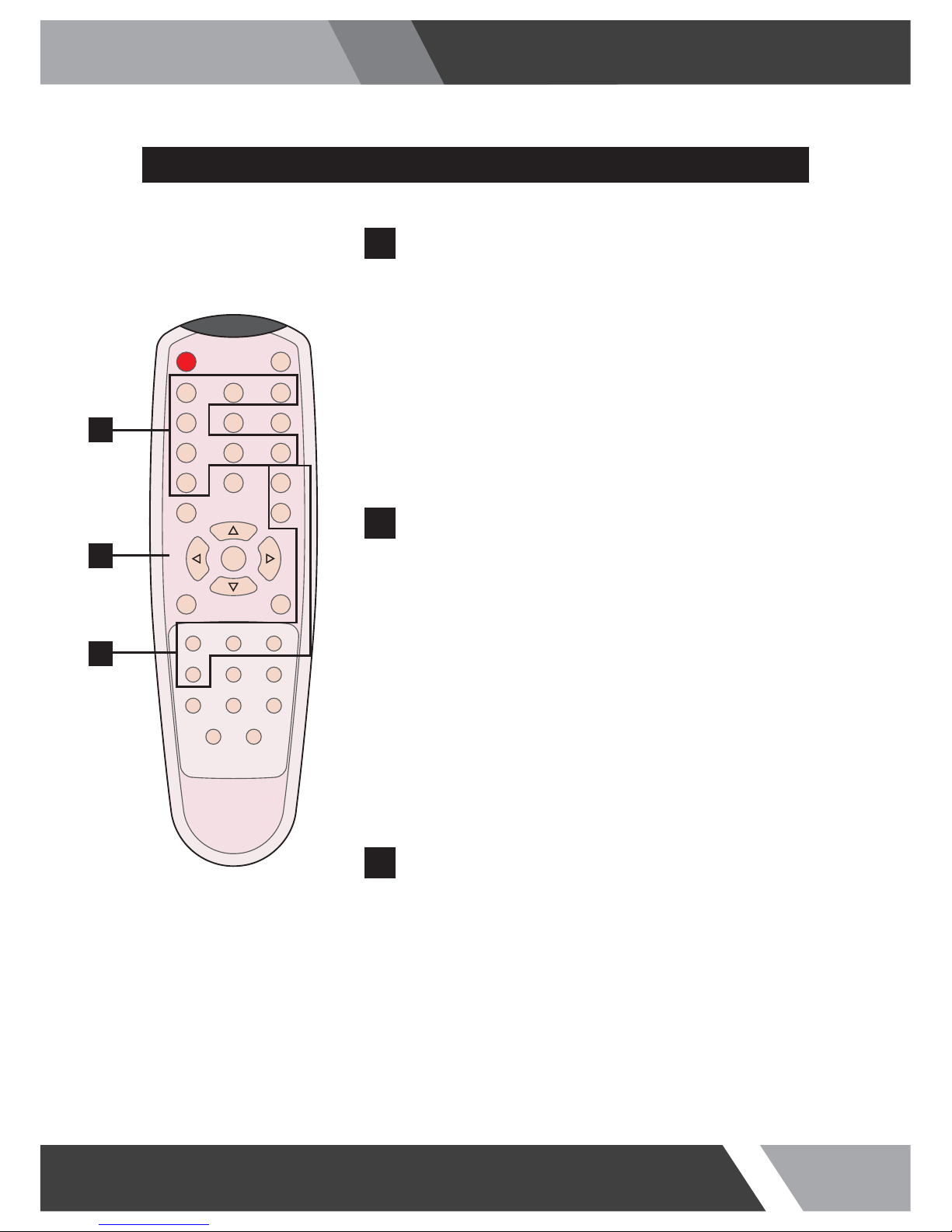
Installation and User's Guide
REMOTE CONTROLLER
MODE SELECT MENU
VIDEO1
Select VIDEO1 mode
VIDEO2
Select VIDEO2 mode
S-VIDEO
Select S-VIDEO mode
VGA (RGB)
Select VGA mode
DVI
Select DVI mode
HDMI1
Select HDMI1 mode
COMPONENT
Select COMPONENT mode
HDMI2
Select HDMI2 mode
POWER
Turn ON / OFF the monitor
MUTE
Turn ON / OFF the sound
AUTO
Auto adjust position of the screen (in VGA mode)
COLOR TEMPERATURE
Select color temperature of the screen
SCAN MODE
Select the scan mode of the screen
VOL- / VOL+
Increase / Decrease the volume level
MENU / EXIT
Activate and exit the OSD menu
STILL
Freeze the current image
KEY LOCK
Locking the button (Prevent operation)
S. SET
Select between main and PIP audio input
PIP
Activates PIP/PBP mode
P. INPUT
Select an input source for PIP mode
P. LOCATION
Select a location for PIP mode
P. SIZE
Select a size for PIP mode
P. SWAP
Swap between main and PIP input
POWER MUTE
VIDEO1 VIDEO2 S-VIDEO
VGA AUTO COLOR TEMP
DVI HDMI1 COMPONENT
HDMI2 S.SET
SCAN MODE PIP
MENU/EXIT
P.INPUT P.LOCATION
P.SWAP STILL
P.SIZE
KEY LOCK
VOL- VOL+
A
B
C
A
OSD CONTROL MENU
B
PIP CONTROL MENU
C
 Loading...