

ORION ELECTRIC M4C9F User Manual
OWNER'S MANUAL
MANUAL DE INSTRUCCIONES
VIDEO CASSETTE RECORDER
VIDEOGRABADOR DE CASSETTE
MVR4040A
For your protection in the event of theft or loss of this product, please fill in the
information listed below which is for your own personal records.
Por su precaucion en caso de robo o pérdida de este producto, favor de llenar
la información listada baja que es para sus inscripciones personales de usted.
Date of purchase :
Fecha de compra :
Serial No. :
Número de serie :
Place od Purchase :
Lugar de compra :
When shipped from the factory, the TV/CATV menu option is set to the "CATV"
(Cable Television) mode.
If not using CATV (Cable TV), set this menu option to the "TV" mode.
A la salida de fábrica, la opción de menú TV/CATV está en el modo "CATV"
(televisión por cable).
Si no se va a utilizar el CATV (TV cable), cambie la opción de este menú al
modo TV.
Before operating the unit, please read this manual thoroughly.
Antes de utilizar su aparato favor de leer las siguientes instrucciones.
4C93401A-E(C-09) 04.10.99, 12:171
ATTENTION
ATENCION
TV/CATV MODE SELECTION
SELECCION DE MODO DE TV/CATV
ENGLISH
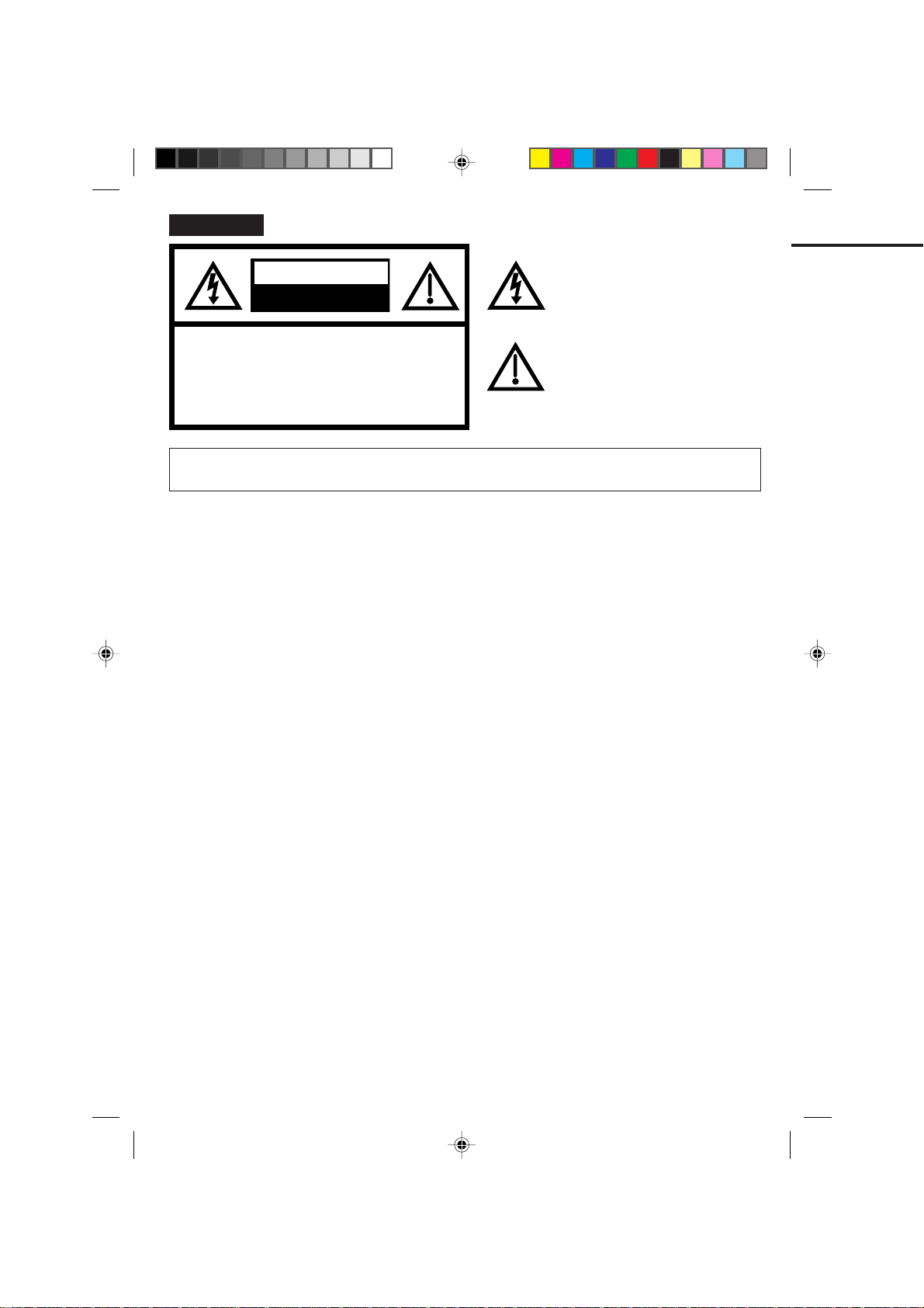
CAUTION:
CAUTION
RISK OF ELECTRIC SHOCK
DO NOT OPEN
TO REDUCE THE RISK OF ELECTRIC
SHOCK, DO NOT REMOVE COVER (OR
BACK). NO USER-SERVICEABLE PARTS
INSIDE. REFER SERVICING TO QUALIFIED SERVICE PERSONNEL.
The lightning flash with arrowhead symbol
within an equilateral triangle is intended to
alert the user to the presence of
uninsulated dangerous voltage within the
product's enclosure that may be of
sufficient magnitude to constitute a risk of
electric shock to persons.
The exclamation point within an equilateral
triangle is intended to alert the user to the
presence of important operating and
maintenance (servicing) instructions in the
literature accompanying the appliance.
WARNING:
WARNING:
CAUTION:
TO REDUCE THE RISK OF FIRE OR ELECTRIC SHOCK, DO NOT EXPOSE THIS APPLIANCE TO
RAIN OR MOISTURE.
This equipment has been tested and found to comply with the limits for a Class B digital device,
pursuant to Part 15 of the FCC Rules. These limits are designed to provide reasonable protection
against harmful interference in a residential installation. This equipment generates, uses, and can
radiate radio frequency energy and, if not installed and used in accordance with the instructions, may
cause harmful interference to radio communications.
However, there is no guarantee that interference will not occur in a particular installation. If this equipment does cause harmful interference to radio or television reception, which can be determined by
turning the equipment off and on, the user is encouraged to try correcting the interference by one or
more of the following measures:
-
Reorient or relocate the receiving antenna.
-
Increase the separation between the equipment and receiver.
-
Connect the equipment into an outlet on a circuit different from that to which the receiver is connected.
-
Consult the dealer or an experienced radio/TV technician for help.
Changes or modifications not expressly approved by the party responsible for compliance with the FCC
Rules could void the user's authority to operate this equipment.
2
4C93401A-E(C-09) 04.10.99, 12:172
IMPORTANT SAFEGUARDS
READ INSTRUCTIONS
1.
All the safety and operating instructions should be read before the unit is operated.
RETAIN INSTRUCTIONS
2.
The safety and operating instructions should be retained for future reference.
HEED WARNINGS
3.
All warnings on the unit and in the operating instructions should be adhered to.
FOLLOW INSTRUCTIONS
4.
All operating and use instructions should be followed.
CLEANING
5.
Unplug this unit from the wall outlet before cleaning. Do not use liquid cleaners or aerosol cleaners.
Use a damp cloth for cleaning.
ATTACHMENTS
6.
Do not use attachments not recommended by the unit's manufacturer as they may cause hazards.
WATER AND MOISTURE
7.
Do not use this unit near water. For example, near a bathtub, washbowl, kitchen sink, or laundry tub, in a wet
basement, or near a swimming pool.
ACCESSORIES
8.
Do not place this unit on an unstable cart, stand, tripod, bracket, or table. The unit may
fall, causing serious injury, and serious damage to the unit. Use only with a cart, stand,
tripod, bracket, or table recommended by the manufacturer.
An appliance and cart combination should be moved with care. Quick stops, excessive
8A.
force, and uneven surfaces may cause the appliance and cart combination to overturn.
VENTILATION
9.
Slots and openings in the cabinet and in the back or bottom are provided for ventilation and to ensure reliable
operation of the unit and to protect it from overheating. These openings must not be blocked or covered. The
openings should never be blocked by placing the unit on a bed, sofa, rug, or other similar surface. This unit
should never be placed near or over a radiator or heat source. This unit should not be placed in built-in installations such as a bookcase or rack unless proper ventilation is provided or the manufacturer's instructions have
been adhered to.
POWER SOURCES
10.
This unit should be operated only from the type of power source indicated on the rating plate. If you are not
sure of the type of power supply to your home, consult your appliance dealer or local power company. For units
intended to operate from battery power, or other sources, refer to the operating instructions.
GROUNDING OR POLARIZATION
11.
This unit is equipped with a polarized alternating-current line plug (a plug having one blade wider than the
other). This plug will fit into the power outlet only one way. This is a safety feature. If you are unable to insert
the plug fully into the outlet, try reversing the plug. If the plug should still fail to fit, contact your electrician to
replace your obsolete outlet. Do not defeat the safety purpose of the polarized plug If your unit is equipped with a
3-wire grounding-type plug, a plug having a third (grounding) pin, this plug will only fit into a grounding-type
power outlet. This too, is a safety feature. If you are unable to insert the plug into the outlet, contact your
electrician to replace your obsolete outlet.
Do not defeat the safety purpose of the grounding-type plug.
PORTABLE CART WARNING
(symbol provided by RETAC)
S3125A
ENGLISH
4C93401A-E(C-09) 04.10.99, 12:173
3

IMPORT ANT SAFEGUARDS (CONTINUED)
12.
POWER-CORD PROTECTION
Power-supply cords should be routed so that they are not likely to be walked on or pinched by items placed
upon or against them, paying particular attention to cords at plugs, convenience receptacles, and the point
where they exit from the appliance.
13.
LIGHTNING
To protect your unit from a lightning storm, or when it is left unattended and unused for long periods of time,
unplug it from the wall outlet and disconnect the antenna or cable system. This will prevent damage to the unit
due to lightning and power line surges.
14.
POWER LINES
An outside antenna system should not be located in the vicinity of overhead power lines or other electric light or
power circuits, or where it can fall into such power lines or circuits. When installing an outside antenna system,
extreme care should be taken to keep from touching such power lines or circuits, as contact with them might be
fatal.
15.
OVERLOADING
Do not overload wall outlets and extension cords, as this can result in a risk of fire or electric shock.
16.
OBJECT AND LIQUID ENTRY
Do not push objects through any openings in this unit as they may touch dangerous voltage points or short out
parts that could result in fire or electric shock. Never spill or spray any type of liquid into the unit.
17.
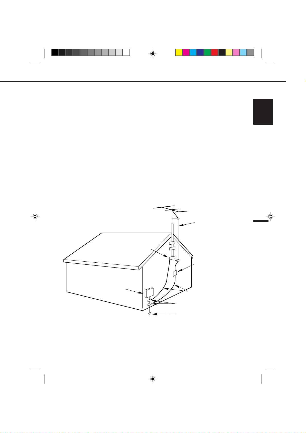
OUTDOOR ANTENNA GROUNDING
If an outside antenna or cable system is connected to the unit, be sure the antenna or cable system is grounded
so as to provide some protection against voltage surges and built-up static charges. Section 810 of the National
Electrical Code, ANSI/NFPA 70, provides information with respect to proper grounding of the mast and supporting structure, grounding of the lead-in wire to an antenna discharge unit, size of grounding conductors, location
of antenna discharge unit, connection to grounding electrodes, and requirements for the grounding electrode.
18.
SERVICING
Do not attempt to service this unit yourself as opening or removing covers may expose you to dangerous
voltage or other hazards. Refer all servicing to qualified service personnel.
19.
DAMAGE REQUIRING SERVICE
Unplug this unit from the wall outlet and refer servicing to qualified service personnel under the following
conditions:
a.
When the power-supply cord or plug is damaged.
b.
If liquid has been spilled, or objects have fallen into the unit.
c.
If the unit has been exposed to rain or water.
d.
If the unit does not operate normally by following the operating instructions. Adjust only those
controls that are covered by the operating instructions, as an improper adjustment of other controls
may result in damage and will often require extensive work by a qualified technician to restore the
unit to its normal operation.
e.
If the unit has been dropped or the cabinet has been damaged.
f.
When the unit exhibits a distinct change in performance, this indicates a need for service.
20.
REPLACEMENT PARTS
When replacement parts are required, be sure the service technician uses replacement parts specified by the
manufacturer or those that have the same characteristics as the original parts.
Unauthorized substitutions may result in fire, electric shock or other hazards.
4
4C93401A-E(C-09) 04.10.99, 12:174
SAFETY CHECK
21.
Upon completion of any service or repairs to this unit, ask the service technician to perform safety checks to
determine that the unit is in proper operating condition.
WALL OR CEILING MOUNTING
22.
The product should be mounted to a wall or ceiling only as recommended by the manufacturer.
HEAT
23.
The product should be situated away from heat sources such as radiators, heat registers, stoves, or other
products (including amplifiers) that produce heat.
NOTE TO CATV SYSTEM INSTALLER
24.
This reminder is provided to call the CATV system installer's attention to Article 820-40 of the NEC that provides
guidelines for proper grounding and, in particular, specifies that the cable ground shall be connected to the
grounding system of the building, as close to the point of cable entry as practical.
ENGLISH
S2898A
EXAMPLE OF ANTENNA GROUNDING AS PER THE
ELECTRIC
SERVICE
EQUIPMENT
NATIONAL ELECTRICAL CODE
GROUND
CLAMP
NEC-NATIONAL ELECTRICAL CODE
ANTENNA
LEAD IN
WIRE
ANTENNA
DISCHARGE UNIT
(NEC SECTION 810-20)
GROUNDING CONDUCTORS
(NEC SECTION 810-21)
GROUND CLAMPS
POWER SERVICE GROUNDING
ELECTRODE SYSTEM
(NEC ART 250, PART H)
4C93401A-E(C-09) 04.10.99, 12:175
5

FEATURES
High Quality Picture Technology - This video cassette recorder marked "HQ" incorporates VHS high quality
technology. A built-in detail enhancer is used to boost the recorded signal and provide maximum picture
quality in playback. It is compatible with other VHS video cassette recorders.
Frequency Synthesized Tuning - Quartz locked direct access tuner automatically locks in each channel for
perfect reception.
4 Video Heads - Provides optimal picture quality for special effects playback.
Hi-Fi Stereo Sound - With a frequency response of 20 to 20,000 Hz and a dynamic range of better than 90dB,
this VCR provides a level of excellence that rivals compact discs.
Full Load Tape Transport - Permits rapid access between modes.
8-Program/1-Month Programmable Timer with Everyday/Every Week Capability - The built-in timer allows
automatic absentee recording of up to 8 TV programs within 1month. It is also possible to record a program
which is broadcast at the same time everyday or every week.
On-Screen Display and Programming - When you select a channel or make other changes, the TV will show
an indicator on the screen for a few seconds. Clock settings, timer setting and other set-up operations can be
carried out using the on-screen display menu system.
Digital Auto Tracking - Automatically adjusts tracking during playback for the best possible picture.
181 Channel Tuner - Receives standard VHF and UHF broadcast channels and up to 113 cable channels.
One-Touch Timer Recording (OTR) - Simply by pressing the REC/OTR button, the VCR can be programmed
for up to 5 hours of recording with an immediate start.
Automatic Power On - When loading a cassette tape, this VCR will automatically turn on.
Automatic Playback - When loading a cassette tape without the erase prevention tab, this VCR will
automatically turn on and play back the cassette tape at the correct speed.
Automatic Rewind-Stop-Eject-Power Off - When a tape reaches its end during playback and recording, it will
automatically stop, rewind, stop, eject the tape and the VCR will turn off.
Automatic Repeat Play System - When the AUTO REPEAT option is turned on, this VCR will automatically
play back the same cassette tape repeatedly.
On-Screen 3 Language Display - You can select one of 3 languages; English, Spanish or French, for on-
screen programming.
Variable Speed Slow Motion - This VCR provides Variable speed slow motion which offers steady, noise free
playback at 1/5-1/30 normal speed.
Frame by Frame Advance - Press the SLOW button during still playback to advance the tape one frame at a
time.
Skip Search - When the SKIP SEARCH button is pressed during playback, the TV/VCR will automatically
search forward in 30 second increments to amaximum of 3 minutes with each press of the SKIP SEARCH
button, and then return to normal playback.
Real Time Tape Counter with Zero Return - The counter displays real tape time and the zero return function
can be used to return the tape to a preselected position (00:00:00) while the counter can be used to locate
programs.
TV Monitor - When the TV MONI. (Monitor) button on the remote control is pressed during playback, the TV
channel selected on the VCR can be viewed.
Channel Skip - An unwanted channel can be deleted when using the CHANNEL ▲ or ▼ button.
Fluorescent Multi-Function Display - Selected functions are immediately indicated on the display.
2 Speed Picture Search - 3 or 5 times normal speed in SP mode (7X or 9X in LP and 9X or 15X in SLP).
3 Speed Record/Playback - Records and plays three tape speeds (SP, LP, SLP).
Stereo/SAP Reception - This VCR is designed to receive stereo and separate audio program (SAP)
broadcasts where available.
Auto Head Cleaning System - Cleans the video heads automatically when a cassette tape is loaded and
ejected.
6
4C93401A-E(C-09) 04.10.99, 12:176
TABLE OF CONTENTS
We recommend that you carefully read the descriptions and operating procedures contained in this Owner's
Manual prior to operating your new VCR.
PRECAUTIONS
PRECAUTIONS ....................................................................................................................................................... 8
LOCATION OF CONTROLS.................................................................................................................................. 10
REMOTE CONTROL ............................................................................................................................................. 12
BASIC CONNECTIONS......................................................................................................................................... 14
CATV (CABLE TV) CONNECTIONS ..................................................................................................................... 18
AUDIO/VIDEO CONNECTIONS ............................................................................................................................ 22
SETTING THE VIDEO CHANNEL ......................................................................................................................... 23
ON-SCREEN LANGUAGE SELECTION ............................................................................................................... 24
SETTING THE CLOCK .......................................................................................................................................... 25
SETTING THE CHANNELS................................................................................................................................... 26
NOISE ELIMINATION (BLUE SCREEN) ............................................................................................................... 29
ENGLISH
PLAYBACK
LOADING AND UNLOADING VIDEO CASSETTE TAPES ......................................................................................30
PLAYBACK ............................................................................................................................................................ 31
SPECIAL PLAYBACK ............................................................................................................................................ 33
RECORDING
RECORDING A TV PROGRAM............................................................................................................................. 36
ONE TOUCH TIMER RECORDING (OTR) ........................................................................................................... 39
SETTING THE TIMER RECORDING .................................................................................................................... 40
ADDITIONAL INFORMATION
ON-SCREEN FUNCTION DISPLAY...................................................................................................................... 43
USING ZERO RETURN......................................................................................................................................... 44
VIDEO INDEX SEARCH SYSTEM (INDEX).......................................................................................................... 45
STEREO RECORDING AND PLAYBACK............................................................................................................. 46
SEPARATE AUDIO PROGRAM (SAP) ................................................................................................................. 47
DUPLICATING A VIDEO TAPE ............................................................................................................................. 48
VIDEO HEAD CLEANING...................................................................................................................................... 49
BEFORE REQUESTING SERVICE....................................................................................................................... 50
SPECIFICATIONS ................................................................................................................................................. 52
4C93401A-E(C-09) 04.10.99, 12:177
7
PRECAUTIONS
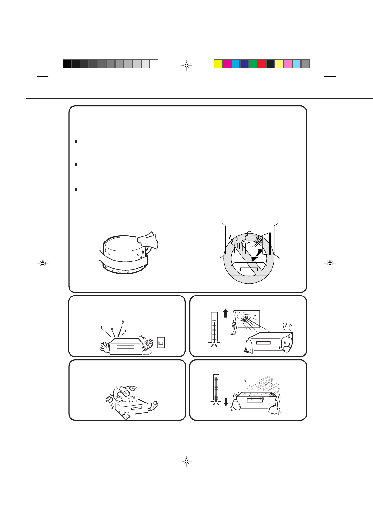
MOISTURE CONDENSATION
DO NOT OPERATE THIS VCR FOR AT LEAST TWO OR THREE HOURS WHEN MOISTURE IN THE AIR
CONDENSES ON THE VCR.
WHAT IS MOISTURE CONDENSATION?
When a cold liquid is poured into a glass, for example, water vapor in the air will condense on the surface of the
glass. This is called moisture condensation.
MOISTURE WILL CONDENSE ON THE UNIT IN THE FOLLOWING CASES;
When you move this VCR from a cold to a warm place.
•
After heating a cold room or under extremely humid conditions.
•
WHEN YOU EXPERIENCE THE ABOVE CONDITIONS,
Plug the power cord into an AC outlet, set the power switch to ON and leave the unit at room temperature until
moisture condensation disappears.
Depending on the surrounding conditions, this may take two or three hours.
Head Drum
Video Tape
If you cause a static discharge when touching the
VCR, and the VCR fails to function, simply unplug the
unit from the wall outlet, wait a few minutes and plug
it back in. The VCR should return to normal operation.
Do not place the VCR on or near appliances which
may cause electromagnetic interference, e.g. TV ,
speakers, etc. Doing so may cause erratic operation
of the VCR including picture and/or sound distortion
or noise.
8
4C93401A-E(C-09) 04.10.99, 12:188
Avoid extreme heat.
104
°
F
(40
°
C)
Avoid extreme cold.
(5°C)
41
°
F
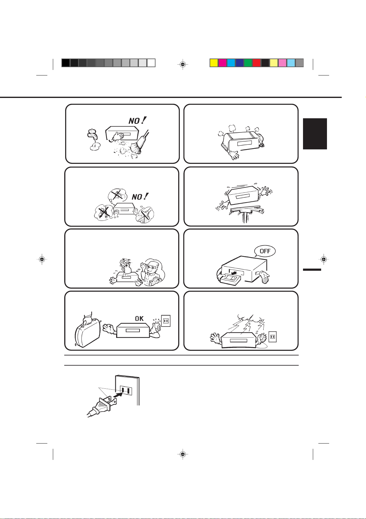
Avoid extreme moisture and dust.
The ventilation holes prevent overheating. Do not
block or cover these holes. Especially avoid covering
the holes with soft materials such as cloth or paper.
ENGLISH
Do not insert fingers or any other objects into the
cassette loading slot. Do not spray cleaner or wax
directly on the VCR or use forced air to remove dust.
Keep the VCR away from flower vases, sinks, etc.
If liquids should be spilled into the VCR, serious
damage will result. If you spill any liquids into the
VCR, unplug the AC power cord immediately and
consult qualified service personnel before attempting
to use the VCR again.
When you leave your home for a long time, unplug
the AC power cord.
Avoid places subject to strong vibration. Use in a
horizontal (flat) position only.
When you finish operating the VCR, always unload
the cassette and turn off the power.
To protect the VCR from a lightning storm, unplug
the AC power cord from the wall outlet and
disconnect the antenna.
AC Outlet
Wider Hole
and Blade
Polarized AC Cord Plug
(One blade is wider than the other.)
4C93401A-E(C-09) 04.10.99, 12:189
POWER SOURCE
TO USE AC POWER SOURCE
Use the AC polarized line cord provided for operation on AC. Insert the
AC cord plug into a standard 120V 60Hz polarized AC outlet.
NOTES:
1. Never connect the AC line cord plug to other than the specified
voltage (120V 60Hz). Use the attached power cord only.
2. If the polarized AC cord does not fit into a non-polarized AC
outlet, do not attempt to file or cut the blade. It is the user’s
responsibility to have an electrician replace the obsolete outlet.
3. If you cause a static discharge when touching the unit, and the
unit fails to function, simply unplug the unit, from the AC outlet,
wait a few minutes, and plug it back in. The unit should return to
normal operation.
9
LOCATION OF CONTROLS
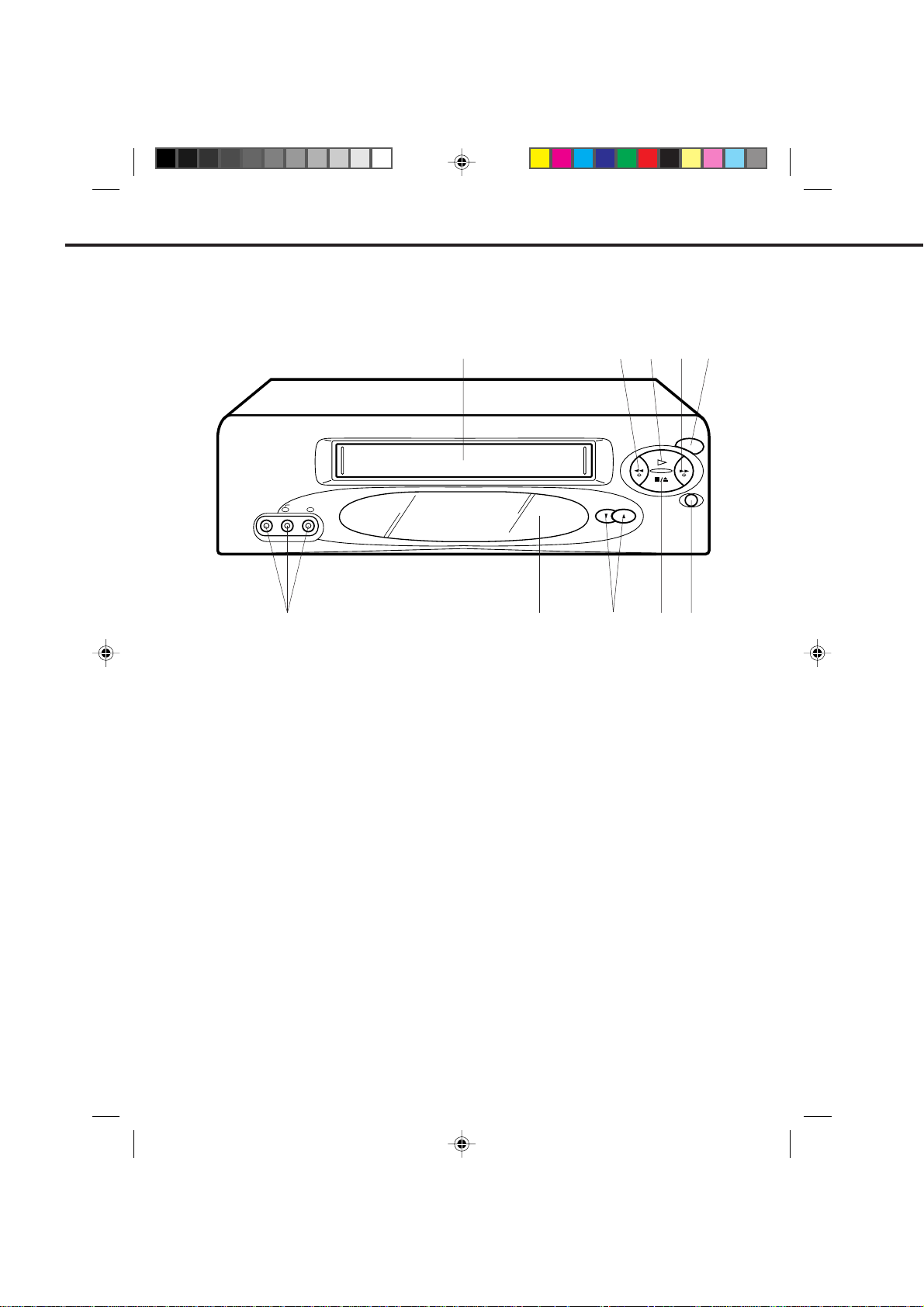
FRONT
MONO
VIDEO IN
AUDIO IN
L R
10
DESCRIPTION OF CONTROLS
1.
Cassette Loading Slot - To insert or remove a
video tape.
2.
REW button - In the STOP mode, this button rapidly
winds the tape backwards. In the PLAY mode, this
button activates Reverse Search.
1 2
9
7.
STOP/EJECT button - Press once to stop the tape
CHANNEL
8
REW
3
PLAY
STOP/EJECT
in any mode. Press again (on the VCR) to eject
the tape.
8.
CHANNEL ▲ / ▼ buttons - Used to select a
channel for viewing or recording.
45
POWER
F.FWD
REC/OTR
67
3.
PLAY button - Press to play a prerecorded tape.
4.
F. FWD button - In the STOP mode, this button
rapidly winds the tape forward. In the PLAY mode,
this button activates Forward Search.
5.
POWER button - Turns the VCR power on and off.
6.
REC/OTR button - Press once to start normal
recording. Additional presses activate One Touch
Recording.
10
4C93401A-E(P10-19) 04.10.99, 12:1610
9.
Remote Sensor - Signals from the Remote Control
are received here.
10.
AUDIO (L/R)/VIDEO IN Jacks - Audio (L/R) and
video signal cables from an external source can be
connected here.
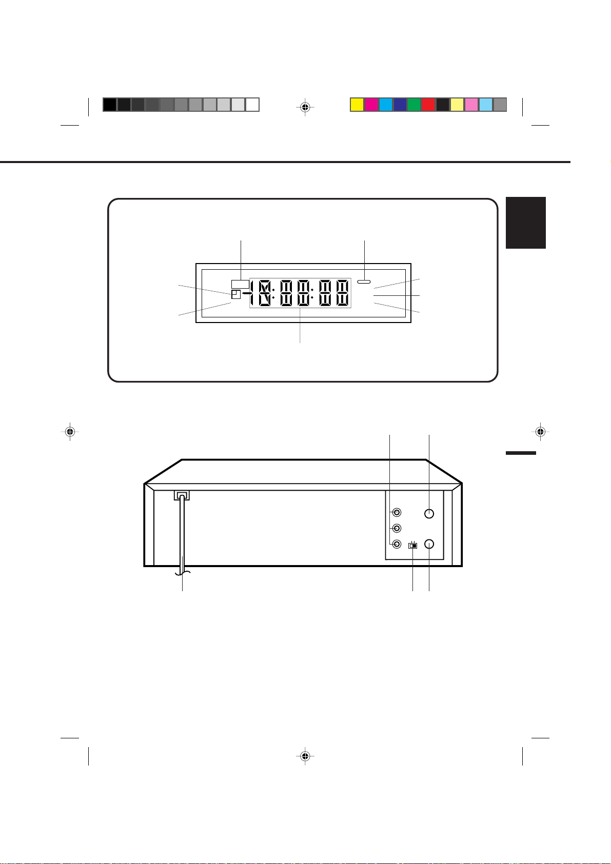
FLUORESCENT DISPLAY
REAR
Timer Record
Tape Speed
One Touch Timer
Recording
OTR
SLP
Multi-Function Display
LOCATION OF CONNECTORS
POWER indicator
VCR
ATR
APM
1
VIDEO
AUDIO
VCR
ATR (Auto Tracking)
AM/PM
UHF/VHF
OUT
IN(ANT)
L
OUT(TV)
3CH4
R
ENGLISH
2
5 3
DESCRIPTION OF CONTROLS
AUDIO (L/R)/VIDEO OUT Jacks - Used to output
1.
audio (L/R) and video signals to a TV, amplifier or
VCR.
VHF/UHF IN (ANT) Jack - Connect a VHF/UHF
2.
antenna or CATV cable to this jack.
VHF/UHF OUT (TV) Jack - Used to output VHF/
3.
UHF or CATV signals to a TV.
4C93401A-E(P10-19) 04.10.99, 12:1611
4
4.5.3/4 Channel Selector Switch - Selects the channel
through which the VCR outputs its signal to a TV.
AC Power Cord - Connect to a 120V 60Hz outlet.
11
REMOTE CONTROL
1
2
POWER
12
3
45
789
4
5
6
7
8
9
10
11
12
13
14
15
0
AUTO
TRACKING
CLOCK/
COUNT
COUNTER
RESET
RETURN
SELECT
INDEX
INPUT ENTER CANCELAUDIO
SLOWSLOW
PAUSE/STILL STOP
REW
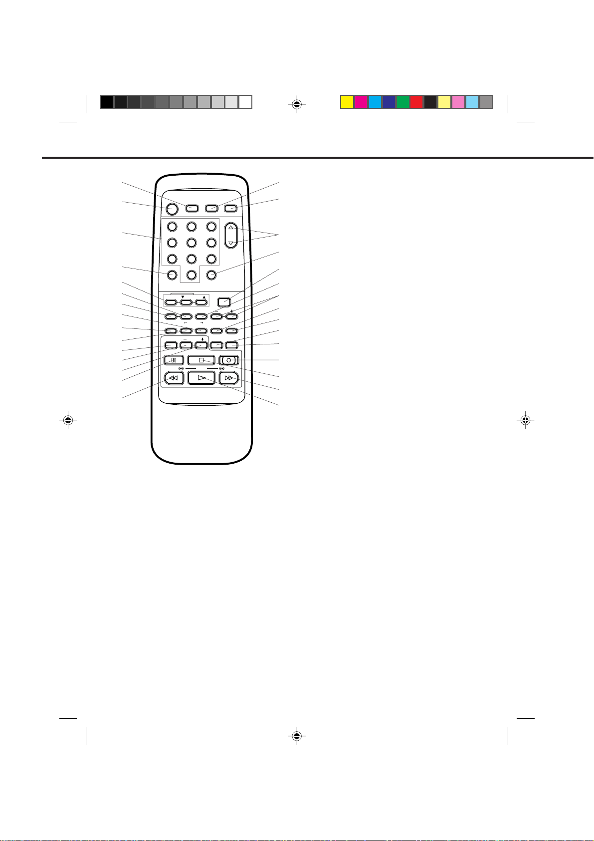
DESCRIPTION OF BUTTONS
TIMER REC button - Used to set the VCR to start
1.
recording at a preset time.
POWER button - Turns the VCR power on and off.
2.
Direct Channel Selection buttons (0-9) - Allow
3.
direct access to any channel.
CALL button - Displays the status of the unit on the
4.
TV screen.
DIGITAL AUTO/MANUAL TRACKING buttons -
5.
Allow automatic or manual adjustment of tracking to
minimize picture noise during playback.
COUNT RESET button - Resets the Real Time
6.
Counter to "00:00:00".
CLOCK/COUNTER selector button - Switches
7.
between the clock and the real time tape counter.
AUDIO SELECT button - Switches sound between
8.
mono and stereo, and SAP when receiveing
broadcasts in stereo or SAP.
EJECTTIMER REC TV MONI.
CHANNEL
3
6
TV/VCRCALL
MENU
ZERO
SET
SKIP
SPEED
SEARCH
REC/OTR
PLAY F.FWD
9.
16
17
INDEX button - Used to search for the INDEX mark.
10.
INPUT SELECT button - Switches the program for
viewing between the VCR and external input
sources.
11.
SLOW button - Press to play back a tape in slow
motion or to advance the tape one frame at a time
18
19
20
21
22
23
24
25
26
27
28
29
30
during still playback.
12.
SLOW – button - Press to speed down slow motion
playback until it is 1/30 of normal speed playback.
SLOW + button - Press to speed up slow motion
13.
playback until it is 1/5 of normal speed playback.
PAUSE/STILL button - During recording, this
14.
button temporarily stops the tape. During playback, it
stops the tape and displays a still image on the TV
screen.
REW button - In the STOP mode, this button
15.
rapidly winds the tape backwards. In the PLAY
mode, this button activates Reverse Search.
TV MONI. (Monitor) button - Used to temporarily
16.
view a TV channel selected on the VCR while in the
playback mode.
EJECT button - Press to eject the tape.
17.
CHANNEL ▲ / ▼ buttons - Used to select a
18.
channel for viewing or recording.
TV/VCR selector button - Switches between TV
19.
and VCR.
MENU button - Press to display the on-screen menu
20.
function.
ZERO RETURN button - Used to stop the tape
21.
when the counter reaches "00:00:00".
SET +/– buttons - Used to set or adjust in the menu
22.
mode.
ENTER button - Used to enter information in the
23.
menu mode.
CANCEL button - Used to clear the selected timer
24.
recording program and to move the cursor backward
for correction.
SPEED (SP/LP/SLP) selector button - Sets
25.
the tape speed for recording.
SKIP SEARCH button - Press in the playback mode
26.
to search forward through approximately 30 seconds
of tape.
REC/OTR button - Press once to start normal
27.
recording. Additional presses activate One-touch
Timer Recording.
STOP button - Press once to stop the tape.
28.
F. FWD button - In the STOP mode, this button
29.
rapidly winds the tape forward. In the PLAY mode,
this button activates Forward Search.
PLAY button - Press to play a prerecorded tape.
30.
12
4C93401A-E(P10-19) 04.10.99, 12:1612
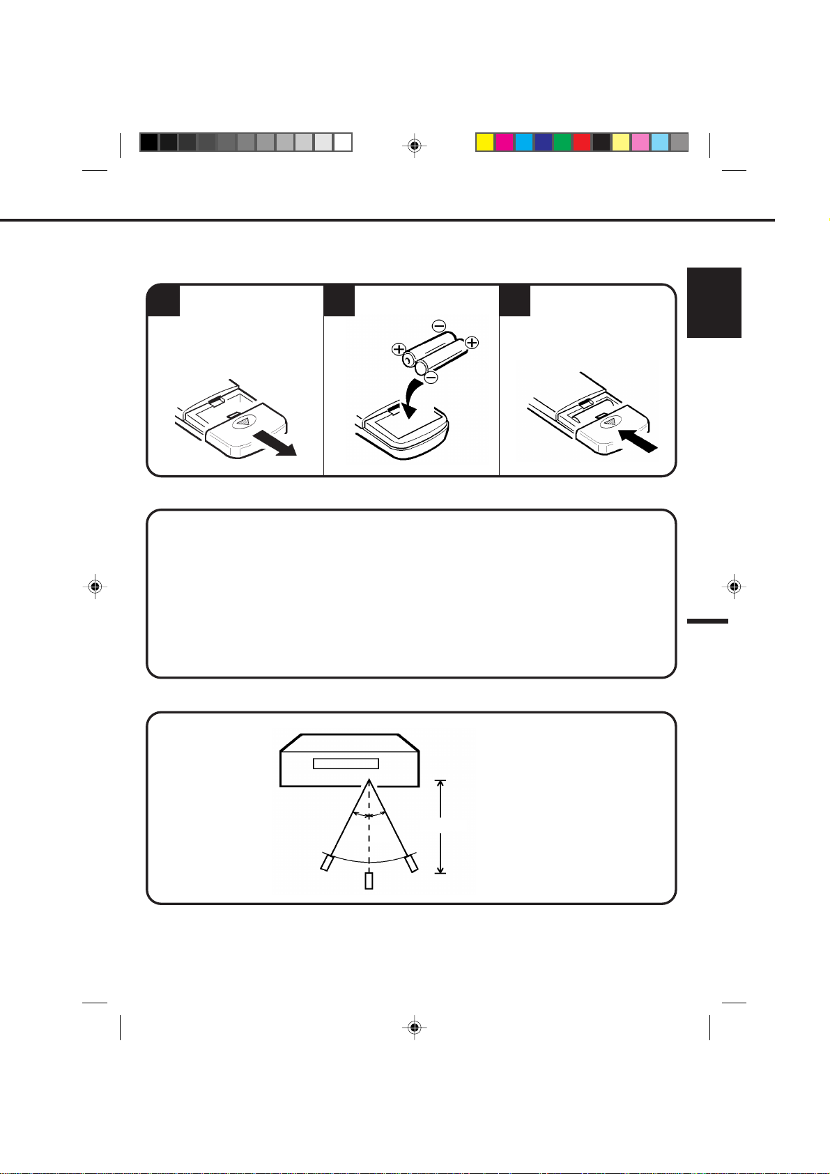
BATTERY INSTALLATION
Open the battery compart-
1
ment cover.
Install two "AAA" (penlight
23
size) batteries.
BATTERY CAUTIONS
Follow these precautions when using batteries in this device:
1.
Use only the size and type of batteries specified.
2.
Be sure to follow the correct polarity when installing the batteries as indicated in the battery compartment.
Reversed batteries may cause damage to the device.
3.
Do not mix different types of batteries together (e.g. Alkaline and Carbon-zinc) or old batteries with fresh
ones.
4.
If the device is not to be used for a long period of time, remove the batteries to prevent damage or injury
from possible battery leakage.
5.
Do not try to recharge batteries not intended to be recharged; they can overheat and rupture. (Follow
battery manufacturer's directions.)
Replace the cover.
ENGLISH
EFFECTIVE DISTANCE OF THE REMOTE CONTROL TRANSMITTER
30˚
30˚
NOTE: When direct sunlight, an incandescent lamp, fluorescent lamp or any other strong light shines on the
•
Remote Sensor, the remote operation may be unstable.
When there is an obstacle between the VCR and the transmitter, the remote control transmitter may not
•
operate.
4C93401A-E(P10-19) 04.10.99, 12:1613
15 FEET
13

BASIC CONNECTIONS
If you are using an antenna system, follow the instructions on pages 14-17. If you are a cable (CATV) subscriber ,
skip ahead to page 18 for the proper connections.
ANTENNA TO VCR CONNECTION
The VCR must be connected "between" the antenna and the TV . First, disconnect the antenna from the TV and connect
it to the VCR. Then connect the VCR to the TV. Below are 3 common methods of connecting an antenna system to a
VCR. Find the type of antenna system you are using and follow the connection diagram. After you have connected the
antenna to the VCR, follow the instructions on pages 16-17 to connect the VCR to the TV.
COMBINATION VHF/UHF ANTENNA WITH 75 OHM COAXIAL CABLE
1
75 OHM COAXIAL CABLE
COMBINATION VHF/UHF ANTENNA WITH 300 OHM TWIN LEAD (FLAT) WIRE
2
3
SEPARATE VHF AND UHF ANTENNAS
If both VHF and UHF antennas have 300 ohm twin lead (flat) wires, use a combiner having two 300 ohm
NOTE:
inputs and one 75 ohm output.
NOTE:
14
4C93401A-E(P10-19) 04.10.99, 12:1614
A clear picture will not be obtained by the VCR unless the antenna signal is good. Connect the antenna to
•
the VCR properly.
For better quality recording, an indoor antenna or a telescopic antenna is not recommended. The use of an
•
outdoor type antenna is required.
If you are not sure about the connection, please refer to qualified service personnel.
•
300 OHM TWIN LEAD (FLAT) WIRE
UHF
VHF
300 OHM TWIN LEAD (FLAT) WIRE
75 OHM COAXIAL CABLE
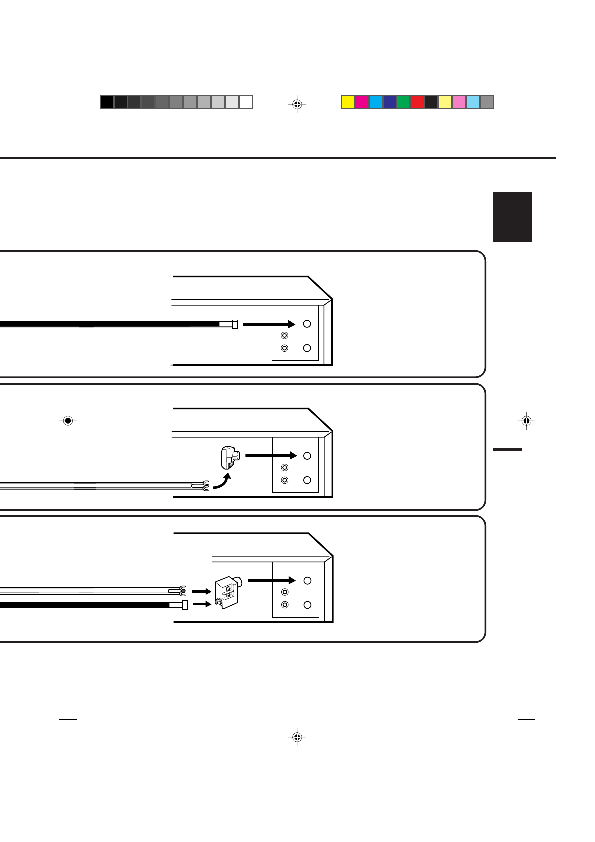
This VCR has a single 75 ohm antenna input for connection to an antenna (VHF/UHF) or cable (CATV) system.
If you have separate VHF and UHF antennas (number 3 below), use a combiner to connect the antennas to
the VCR.
VCR
NOTE: IF A VHF OR UHF
ANTENNA IS USED, SET THE TV/
CATV MENU OPTION TO THE
"TV" MODE.
NOTE: IF A VHF OR UHF
ANTENNA IS USED, SET THE TV/
CATV MENU OPTION TO THE
"TV" MODE.
MATCHING TRANSFORMER
300 OHM INPUT
75 OHM OUTPUT
(NOT SUPPLIED)
IN
OUT
VCR
IN
OUT
ENGLISH
75/300 OHM INPUTS
COMBINER
75 OHM OUTPUT
(NOT SUPPLIED)
4C93401A-E(P10-19) 04.10.99, 12:1615
VCR
IN
OUT
NOTE: IF A VHF OR UHF
ANTENNA IS USED, SET THE TV/
CATV MENU OPTION TO THE
"TV" MODE.
15

BASIC CONNECTIONS (CONTINUED)
VCR TO TV CONNECTION
After you have connected the antenna to the VCR (see pages 14 & 15), you must connect the VCR to the TV.
Below are 3 common methods of connecting your VCR to a TV. Find the type of TV you are using and follow
the connection diagram.
1
IN
OUT
75 OHM COAXIAL CABLE (SUPPLIED)
VCR
2
IN
3
16
4C93401A-E(P10-19) 04.10.99, 12:1616
OUT
75 OHM COAXIAL CABLE (SUPPLIED)
VCR
IN
OUT
75 OHM COAXIAL CABLE (SUPPLIED)
VCR
 Loading...