

Page 1
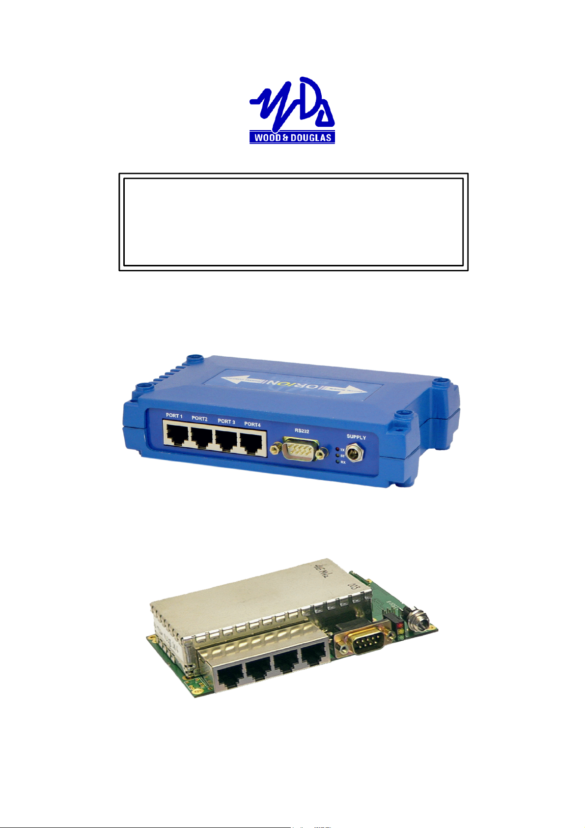
ORION RADIO MODEM WITH I/O
OPERATING INSTRUCTIONS
1892 1335
THIS IS A DRAFT VERSION OF THE MANUAL. THERE MAY BE ERRORS OR
OMISSIONS IN IT, AND YOU USE IT AT YOUR OWN
RISK.
Figure 1 - Orion Radio Modem
Figure 2 - Orion Radio Modem - OEM PCB version
1892 1335 - Orion Radio Modem Operating Instructions - v1.3 / Aug 2006 1
Page 2
OVERVIEW
The Orion is a radio modem with on-board telemetry inputs and outputs. It is available in
a number of different versions to suit different applications, and has many userprogrammable features, which may be locally or remotely set. It is supplied with a
Graphical User Interface (GUI) program which runs under Windows on a PC, and can be
used both to configure the Orion and as an interface to control and display the telemetry
inputs and outputs.
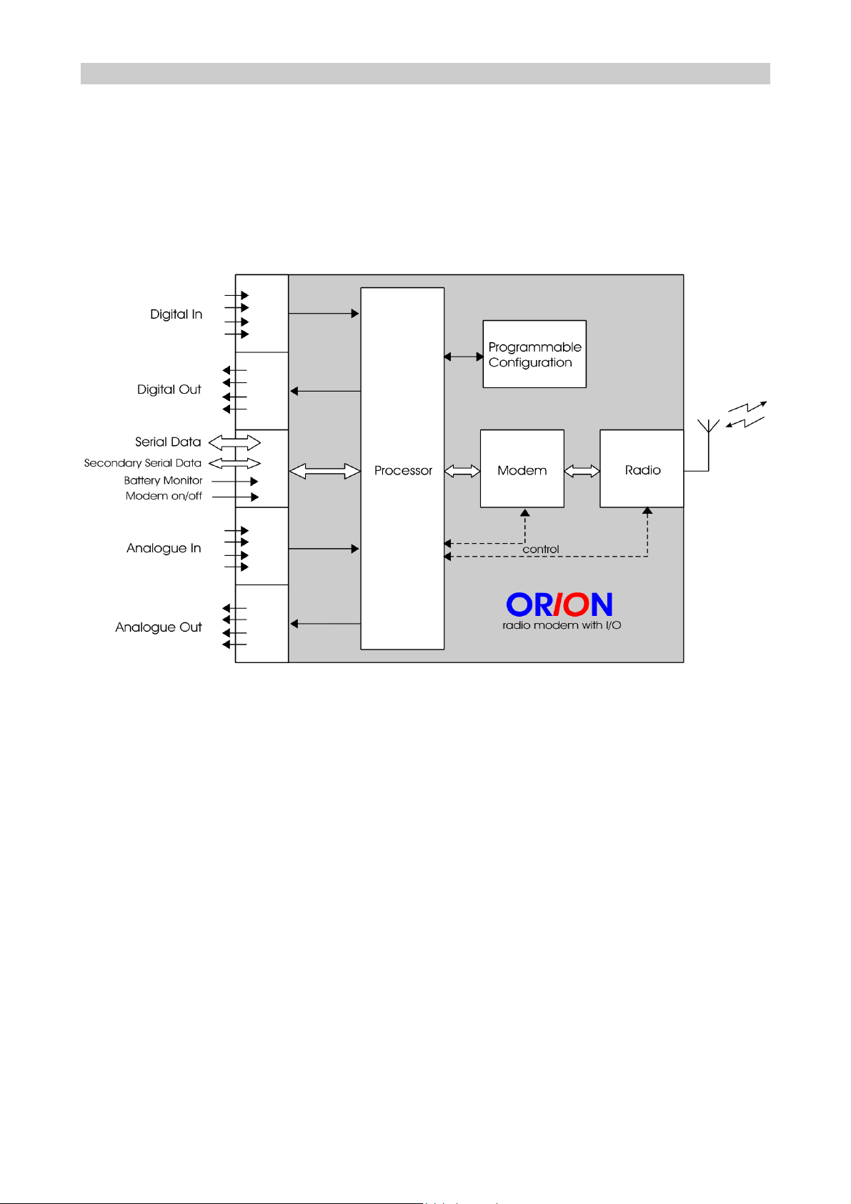
Figure 3 shows the Orion in block diagram form.
Figure 3 - Orion block diagram
Summary of notable features and options:
v Four digital inputs*
v Up to four digital outputs
v Counter input
v Up to four analogue inputs (current loop or voltage)
v Up to four analogue outputs (voltage)
v Floating relay digital output/fail warning option
v RS232/RS422/485 asynchronous data. Secondary channel with RS232.
v Sampling mode transmits any data format
v Unidirectional or half-duplex link, choice of error correction
v Choice of frequency band and power
v AT command set, local or remote programming of most features
2 1892 1335 - Orion Radio Modem Operating Instructions - v1.3 / Aug 2006
Page 3

v One-to-one or master + outstations configuration
v Outstations can be polled, or volunteer data when thresholds are reached
(‘alarms’).
v GUI for simple programming and operation
*The four analogue inputs can also be used to transmit digital data if required
1892 1335 - Orion Radio Modem Operating Instructions - v1.3 / Aug 2006 3
Page 4

OPTIONS WHEN ORDERING
Many options are user-programmable, but the options below must be specified when
ordering so that the correct version of the Orion can be supplied:
OEM PCB version
The Orion is available uncased as a PCB for mounting in OEM equipment.
In/Out capability
The Orion is also available as a straight radio modem without the telemetry in/out
capability.
Frequency band of operation
The Orion can be supplied to operate in the VHF, UHF and higher (e.g. 868MHz) bands.
The radio module in each Orion is built to operate over a certain range of frequencies (its
switching bandwidth) under software control, for example 450-458MHz. Consult Sales at
Wood & Douglas for available frequency bands.
RF Power
The RF power can be chosen from very low powers up to 5W, depending on the radio
module.
Data rate
The Orion can operate at up to 19,200 baud maximum. If a lower data rate, up to 9,600
baud, is acceptable, a version which uses less radio spectrum (12.5kHz rather than
25kHz) can be ordered. (Transmitters and receivers must match.)
RSSI output
Analogue output 1 can be configured as a Received Signal Strength Indication (RSSI)
output.
Serial port mode
The serial port can be configured for RS232, RS422 or RS485 protocols. Serial baud rate
can be adjusted up to 38,400 baud maximum, hardware flow-controlled using RTS/CTS.
4 1892 1335 - Orion Radio Modem Operating Instructions - v1.3 / Aug 2006
Page 5
INSTALLATION
Physical
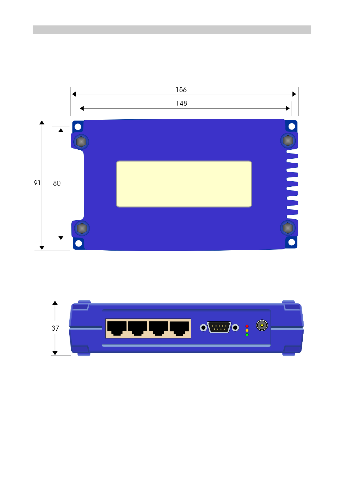
The cased version may be used freestanding or fixed using the four holes provided:
Figure 4 - Orion (cased) dimensions and mounting (mm)
Figure 5 - Orion (cased) clearance (mm)
The PCB version should be mounted using the holes provided, and requires clearances
as shown overleaf.
1892 1335 - Orion Radio Modem Operating Instructions - v1.3 / Aug 2006 5
Page 6
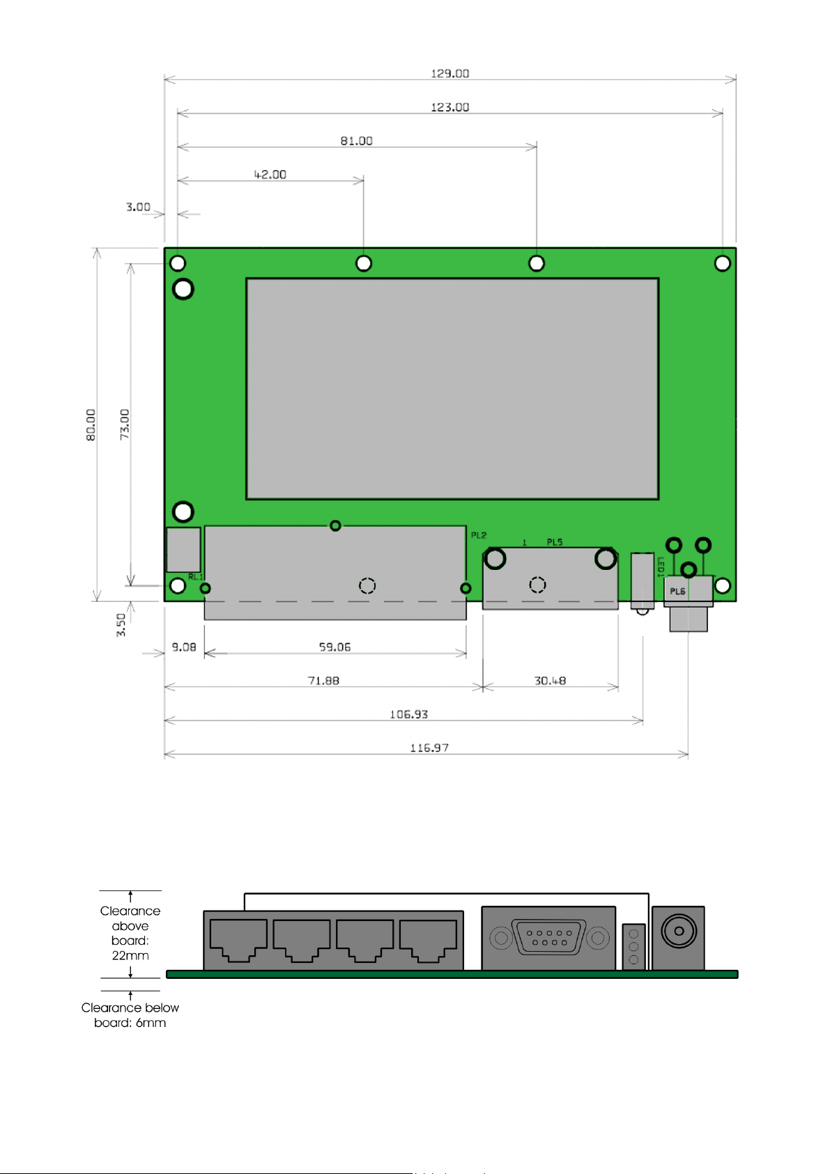
Figure 6 - Dimensions of Orion PCB (mm)
Figure 7 - Required mounting clearances for Orion PCB
6 1892 1335 - Orion Radio Modem Operating Instructions - v1.3 / Aug 2006
Page 7

Connections
Power
Front panel, locking power plug, 2 pole with 2.1mm centre pin.
Centre conductor: +9 to +15V DC
Outer conductor: 0V (connected to unit ground)
Antenna
Female BNC, 50O
Antenna connection for both transmit and receive. The antenna will typically be mounted
directly onto this connector; otherwise the connection to the antenna should be as short
as possible and made in high-quality low-loss coaxial cable.
v Caution: do not power the Orion without an antenna or dummy load
connected, or the unit may be damaged.
Telemetry Ports (when fitted)
Four RJ45 8-way female connectors:
RJ45
Pin No.
Port 1
Digital In
Port 2
Digital Out
Port 3
Analogue In
Port 4
Analogue Out
1 0V Relay NC 0V 0V
2 Digital input 1 Relay Common Analogue input 1 Analogue output 1
or RSSI output
3 0V Relay NO 0V 0V
4 Digital input 2 Digital output 2 Analogue input 2 Analogue output 2
5 0V 0V 0V 0V
6 Digital input 3 Digital output 3 Analogue input 3 Analogue output 3
7 0V 0V 0V 0V
8 Digital input 4 Digital output 4 Analogue input 4 Analogue output 4
1892 1335 - Orion Radio Modem Operating Instructions - v1.3 / Aug 2006 7
Page 8

Serial Port
9-way D-type male connector - NOT a standard serial port
v Protocol (RS232, RS422 or RS485) is fixed by soldered links. See page 10.
Pin No RS232 RS422 RS485
1 SHDN Modem on/off input
If < 0.6V, Modem = OFF
If o/c (internal pull-up to +5V) Modem = ON
2 RXD Receive Data
output
3 TXD Transmit Data
input
4 TXB Secondary
Transmit Data
input
5 0V
6 VSENSE External Battery Monitor input +50VDC max
7 RTS RTS input
8 CTS CTS output OP Receive Data
9 RXB Secondary
Receive Data
output
OP Receive Data
inverting output
IP Transmit Data input NC No function
NC No function NC No function
IP Transmit Data
inverting input
output
NC No function NC No function
IO Inverting
input/output
NC No function
IO Non-inverting
input/output
8 1892 1335 - Orion Radio Modem Operating Instructions - v1.3 / Aug 2006
Page 9
Graphical User Interface (GUI)
The GUI is a program which runs on a PC under Windows, and provides a simple and
convenient way to set up local or remote units before use. It can also be used in
conjunction with the telemetry inputs and outputs as a display and control console (mimic
panel) during normal operation. It is connected to the serial port of the local or master
unit.
v The Orion can also be interrogated and controlled using your own equipment
and software. Again, a connection to the serial port of the local or master
unit is required. AT commands (detailed in Appendix A on page 21) are used
for local units and over-air commands (detailed in Appendix B on page 27)
for remote units.
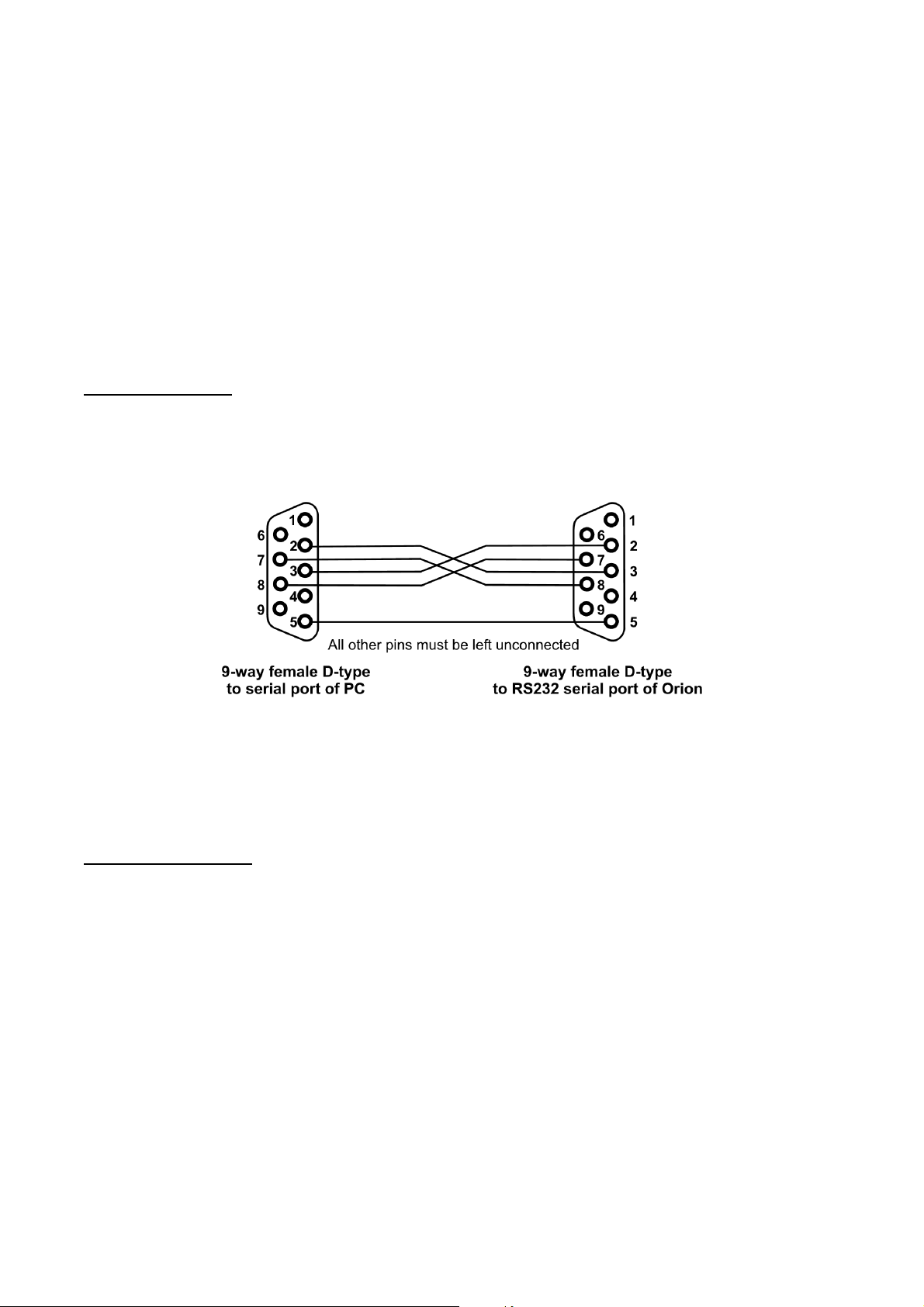
Serial Connection
If the Orion is configured for RS232 serial data, a cable of this pattern should be used to
connect the COM port of the PC which will run the GUI to the serial port of the Orion:
If the Orion is configured for RS422 or RS485 working, the PC must communicate with it
using the matching protocol, and be connected to it with the corresponding serial port
connections shown in the table on page 8.
Software Installation
The GUI software is provided on a CD-ROM with an automatic installer. Insert the CD-
ROM in the PC’s CD drive to auto-run the program which installs the GUI software on your
computer.
v If auto-run is disabled, you should run the file SETUP.EXE in the root
directory of the CD to install the software.
Follow the on-screen instructions to complete the software installation.
The GUI is now ready to run. Keep the CD in a safe place in case it is needed again.
1892 1335 - Orion Radio Modem Operating Instructions - v1.3 / Aug 2006 9
Page 10
SETTING UP AN ORION
The Orion has some options which are chosen when it is ordered (see page 4) and many
which you can configure yourself with hardware links, or soft-configure using data
commands. The best way to set up the soft-configurable options is to connect the
supplied Graphical User Interface (GUI) to the unit, although it is also possible to use your
own equipment using the commands described in Appendix A (page 21) and Appendix B
(page 27).
Hardware Link Settings
In order to change the links, open the case using the four screws, one at each corner, to
access the PCB.
You will need a fine-tipped soldering iron to make links, and a removal tool or aid to break
links.
v This equipment is made with lead-free solder to comply with the RoHS
directive, and you should use lead-free solder when making links.
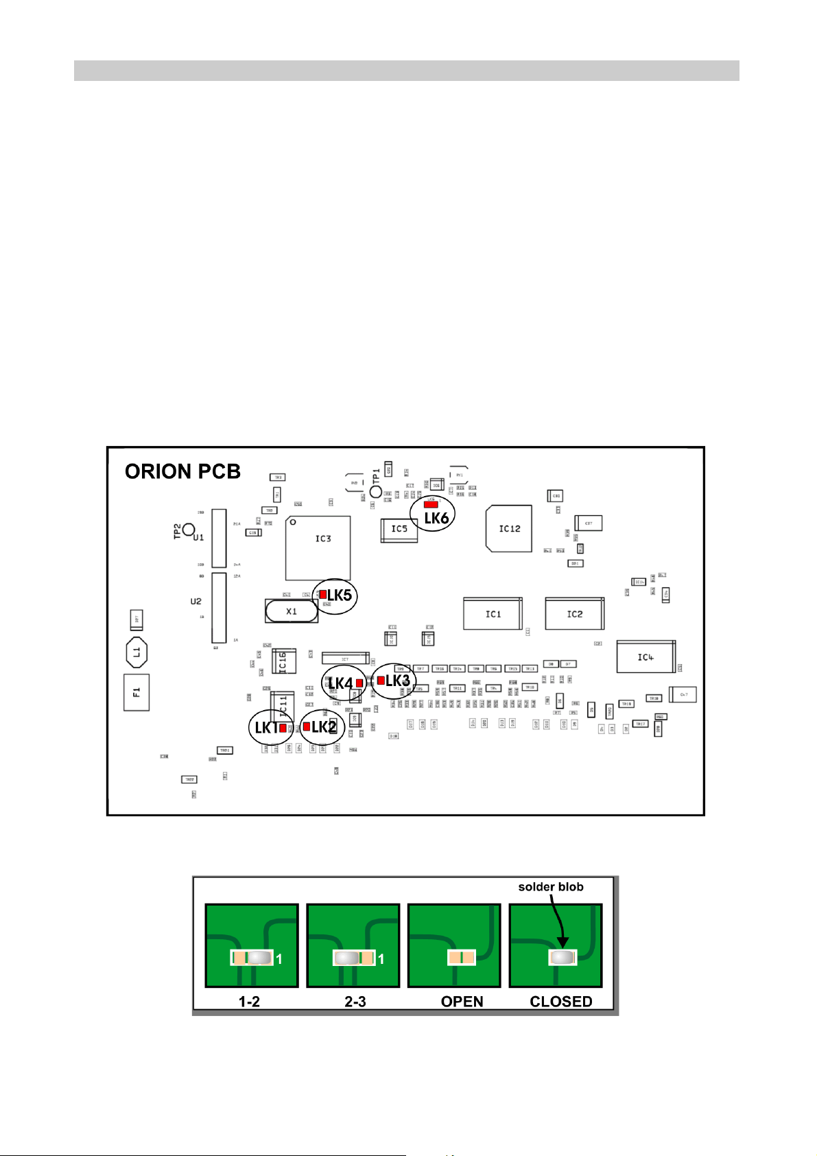
Figure 9 - Link locations
Figure 10 - Making links
10 1892 1335 - Orion Radio Modem Operating Instructions - v1.3 / Aug 2006
Page 11

Links can be closed with a solder blob as shown in Figure 10 to select these options:
Option Choice Links
Protocol RS232 LK1 open
RS422/RS485 LK1 closed
Duplex Full duplex LK2 open
Half duplex LK2 closed
In/Out mode Full I/O + modem LK5 open
Modem only LK5 closed
Use of
Analogue Out 0
Analogue user
output
LK3 open, LK4 closed, LK6
1-2 open
For GMAX radios,
LK6 2-3 closed.
Power level is
RSSI output LK3 closed, LK4 open, LK6
1-2 open
preset HI or LO.
For other radios,
don’t care.
Variable power
control (GMAX
LK3 open, LK4 open, LK6 1-2 closed, LK6 2-3
open
radios only)
Using the GUI
Ensure that the serial comms port of the PC which is used to run the GUI program is
connected to the Orion using a suitable cable as described on page 9. The type of cable
depends on whether your Orion’s serial port uses RS232, RS422 or RS485.
v Note that this is NOT a standard serial cable, which must not be used.
The GUI must have been installed on the PC as described on page 9.
Switch on power to the Orion.
Start the GUI, typically by double-clicking the icon on the desktop, or selecting Start,
Programs, Wood & Douglas, Orion GUI. You should see a display similar to the following,
depending on whether you are currently able to connect to an Orion and what options are
in force:
1892 1335 - Orion Radio Modem Operating Instructions - v1.3 / Aug 2006 11
Page 12
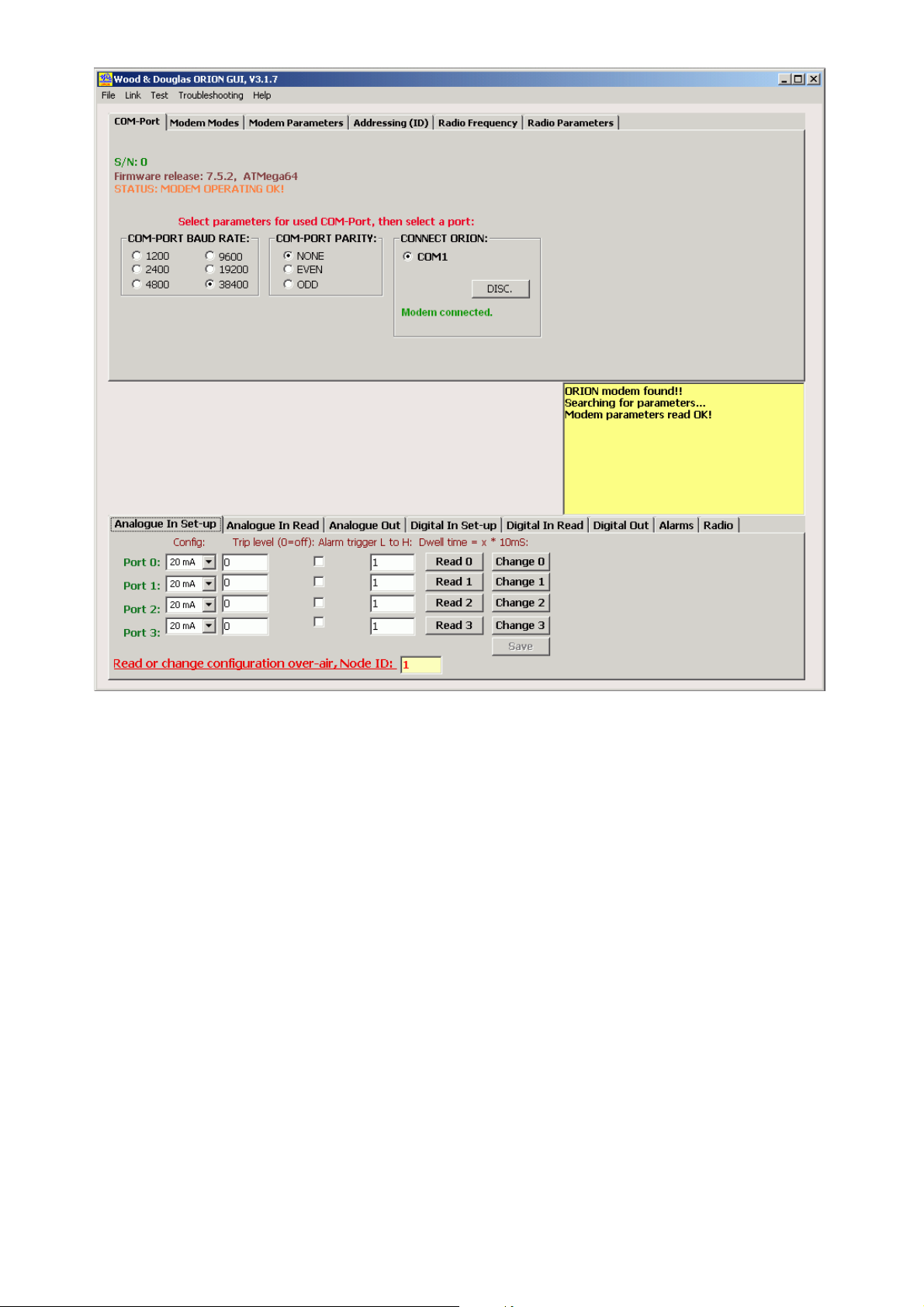
Figure 11 - Orion GUI window
Note the set of tabs at the top which set the Orion up.
The tabs at the bottom are used to set up in/out functions, and also to monitor and control
during operation. These tabs may be modified or absent on your display, depending on
the mode that the Orion is currently in and whether their parameters are relevant or not.
v This section of the manual deals with setting up - see page 20 for details of
operation.
12 1892 1335 - Orion Radio Modem Operating Instructions - v1.3 / Aug 2006
Page 13

COM Ports and General Status
Figure 12 - COM Port tab
This tab is the first one which the GUI presents to you, because the GUI must be set to the
same baud rate and parity as the port on the Orion in order to communicate with it.
If the message Modem connected does not appear immediately, select the correct baud
rate and parity, then click the COMn radio button (even if it is already selected), where n is
the number of the port to which the Orion is connected. The message Modem connected
appears.
To change the baud rate or parity, select the values you want, then select Link, Write
Parameters from the menu bar. A successful outcome is reported in the yellow message
area.
v The baud rate and/or parity do not actually change at the GUI until you click
the one of the COM radio buttons.
v The baud rate and/or parity do not actually change at the Orion until you
disconnect from it.
To disconnect from the Orion, click the DISC button.
Modem Status
You can also read the unit serial number, firmware release and general status on this tab.
If one or more errors exist, this will be displayed together with a single code number which
you can give to Wood & Douglas technical support.
Some possible errors are listed below.
v NO VALID PARAMETERS IN MODEM! (Error code 2)
When the factory set-up was uploaded to the modem FLASH and EEPROM memories, a
parameter check sum was also written. If the check sum calculated by the modem does not
match the written check sum, this error will be generated, indicating that the FLASH and
EEPROM memory contents are corrupt. You can use menu item Troubleshooting,
Reprogram with Factory Settings to correct the parameters, or upload your own custom
settings to the modem in the normal way.
1892 1335 - Orion Radio Modem Operating Instructions - v1.3 / Aug 2006 13
Page 14

v FLASH FACTORY SETTINGS CORRUPT! (Error code 4)
When the modem was first programmed at the factory, a backup factory settings table was
written in the FLASH memory. This is used if it is necessary to invoke the Reprogram with
Factory Settings command. You can write your own custom settings into this backup table
if you wish, using menu item Link, Factory settings, Write, which is password protected.
If this is corrupt, please consult Wood & Douglas technical support for assistance.
v PLL NOT IN LOCK! (Error code 16)
If the radio PLL does not lock, the radio module might be damaged. Turn off power to the
unit, and power it up again. If this does not clear the error, please consult Wood &
Douglas technical support for assistance.
Modem Modes
Figure 13 - Modem Modes tab
Orion units can ‘talk’ to each other in a number of ways to suit your application and the
conditions. This section lists the options and tells you which mode you need to select.
Choose the Modem Modes tab in the GUI, and click to select options.
v The set of tabs at the bottom of the window may change or disappear
depending on the option you choose, and whether or not they are relevant.
Normal Data Modem
The Orion makes an excellent data modem without using its built-in telemetry capabilities.
It has four data modes, which allow for different kinds of data and different levels of error
correction depending on your application. As you might expect, the more error correction
you select, the lower the maximum throughput. (See specifications for figures.)
These modes provide a point-to-point, half-duplex link.
TR caters for non-standard data formats by sampling the input and recreating it at the
other end. Any format can be sent, but no error correction can be provided. The
RTS line must be active as long as data is to be transmitted.
14 1892 1335 - Orion Radio Modem Operating Instructions - v1.3 / Aug 2006
Page 15

TS is the basic two-way link for asynchronous RS232 data. It has no error correction.
TU also provides a two-way asynchronous RS232 data link, but it has Feed-forward
Error Correction (FEC) so that many errors can be corrected.
TP provides a two-way asynchronous RS232 data link with both FEC and requests for
repeat transmission of corrupt packets to provide an error-free link.
TRR
TSR
TUR
configure a modem as a simplex repeater, retransmitting received data to extend
the range of the radio link. They are used in conjunction with the corresponding
TR, TS and TU modes. (Repeater mode is not available for mode TP.)
Several repeaters can be used in the same network, because the repeater will only
re-transmit the same message once if received several times.
Telemetry Options
These modes communicate only telemetry information, not user data.
TMR
TNT
TMX
The simplest telemetry link is where the inputs at one end are mimicked at the
other end. By configuring the master station as TMR, and the outstation as
TNT, the inputs at the outstation are relayed to the master’s outputs.
This is a similar link, but two-way. By configuring the master station as TMX ,
and the outstation as TNX, the inputs at either end are relayed to the outputs at
TNX
the other. Hence this could be used for control as well as data acquisition.
TOM
TOS
This configuration allows one master to control and acquire data from many (up
to 255) outstations. The master is configured as TOM, and each outstation as
TOS, with an ID number so that it can be individually addressed. External
equipment (the GUI for example) is needed at the master to supervise the
operation and receive data. The master’s telemetry inputs and outputs are not
used.
If a repeater is needed for any of these modes, configure it as TUR.
Combination Options
The Orion is capable of passing both user data and telemetry information between the
outstation(s) and the master.
1892 1335 - Orion Radio Modem Operating Instructions - v1.3 / Aug 2006 15
Page 16

TOR
TOT
Single outstation. The master is configured as TOR, and the outstation as TOT.
Data input at the outstation is output at the master’s normal data port, I/O
???and alarm messages are output on the secondary data port. External
equipment (the GUI for example) is needed at the master to supervise the
operation and receive data.
TOX
TOT
Modem Parameter Configuration
The master is configured as TOX, and each outstation as TOT, with an ID
number so that it can be individually addressed. When it is polled by the
master, data input at the outstation is output at the master’s normal data port,
and I/O data and alarm messages are output on the secondary data port. The
secondary data port operates at a fixed data rate of 19200 baud. External
equipment (the GUI for example) is needed at the master to supervise the
operation and receive data.
Figure 14 - Modem Parameters tab
Transmitter key-up time
This time is allowed to elapse before any data is sent, to ensure that the radio is ready.
The value depends on the particular radio fitted.
Squelch to start of preamble
During receive, the modem allows this period to elapse after the squelch has operated
before reporting a missing preamble.
No of preamble blocks
The number of preamble blocks which will be sent after the key-up time. Too few will not
allow the remote receiver to establish sync, too many will waste transmission time. 9 is a
typical value.
16 1892 1335 - Orion Radio Modem Operating Instructions - v1.3 / Aug 2006
Page 17

No. of retries (TP mode only)
If a received packet fails its CRC check, the receiving modem will ask for retransmission.
For each packet, this will be repeated until either a good copy is received, or the number
of retries set here has been reached. A typical setting is 10 - 15.
Max no. of bytes in a data frame (TP mode only)
The maximum number of bytes in each packet as it is transmitted. Select a value from the
drop-down list, which are the only values available. A high value ensures maximum data
throughput where there is a good signal path, whereas a low value is the best compromise
where there is a poor signal path.
RX-TX Priority
Normally, the Orion will not transmit if the squelch indicates that there is already a
transmission on frequency. However, where there is interference, this box may be
checked to transmit regardless.
Inverted TX audio, Inverted RX audio
Some radio modules invert the audio (modem) TX and/or RX signal. Using these
checkboxes, the signal can be restored to the original polarity by correcting the inversion.
Radio Baud Rate
Selects an over-air baud rate appropriate to the radio bandwidth and the data rate you
propose to send over the air. 19200 bps can be used with a 25kHz channel, and 9600 or
4800 bps in a 12.5kHz channel.
Sync Tolerance
Regular sync frames of known content are sent over the link. Sometimes they are
imperfect, but because of forward error correction this does not indicate that the data is
unusable. This value indicates the number of imperfections which can be tolerated, and is
usually set at 4.
AT Commands Guard Time
Sets the minimum time in ms required to elapse either side of the ‘+++’ AT command string
for it to be recognised as such. 15ms is a typical value. See p.21 for details.
ATI3 Test Message Interval
The time which is allowed to elapse in between transmissions of the test string in response
to the ATI3 command, in tens of milliseconds.
1892 1335 - Orion Radio Modem Operating Instructions - v1.3 / Aug 2006 17
Page 18

This space reserved for additional material
18 1892 1335 - Orion Radio Modem Operating Instructions - v1.3 / Aug 2006
Page 19

Telemetry Option Configuration
Depending on which mode you are using the Orion unit in, you may need to set up other
options such as alarm levels.
v These options are not relevant if you are using the unit as a straight modem.
Analogue Input Setup
Figure 15 - Analogue In Set-up
For each input, select:
Type: 20mA input
Alarm threshold: 1 to 1023 - proportion of full scale (0 = never alarm)
Alarm validation period: 1 to 255 - time for which condition must persist (in 10ms
Alarm condition: Greater than or less than threshold level
Digital Input Setup
0 to +5V input
0 to 10V input
blocks)
Figure 16 - Digital In Set-up
1892 1335 - Orion Radio Modem Operating Instructions - v1.3 / Aug 2006 19
Page 20

For each input, select:
Alarm: enable
Alarm validation period: 1 to 255 - time for which condition must persist (in 10ms
Alarm condition: low-high transition
Alarm Behaviour
disable
blocks)
high-low transition
Figure 17 - Alarms
Alarm repeat: 1 to 1023 - alarm is repeated at this interval (in 10ms
blocks) during alarm condition
0 - alarm is sent once when condition first occurs
Alarm retry: 1 to 1023 - when link is unidirectional, alarm will be sent
this number of times to ensure that it gets through.
20 1892 1335 - Orion Radio Modem Operating Instructions - v1.3 / Aug 2006
Page 21

This space reserved for additional material
1892 1335 - Orion Radio Modem Operating Instructions - v1.3 / Aug 2006 21
Page 22

OPERATION
LED Indications
Three LED indicators are visible on the front panel, with the following meanings:
Yellow Status Slow blink (every 2 seconds) indicates normal operation.
Fast flash (5Hz) indicates one of the following:
v the receiver is detecting carrier with no data modulated on it
v the modem is in AT command mode
v the radio module is reporting a lock error
v the modem is not configured
Green RX Steady on state indicates valid data reception or
communication with the GUI software.
Red TX On when the radio is transmitting.
22 1892 1335 - Orion Radio Modem Operating Instructions - v1.3 / Aug 2006
Page 23

APPENDIX A: AT COMMAND CODES
Normally the GUI is the best way to configure, control and interrogate a local Orion unit.
However, if you want to use your own equipment and software to do this, you can use the
serial port to send ASCII AT commands and receive replies, which are listed in this
Appendix.
The modem is configurable via the same port as is normally used for data. To configure it,
you need to connect a terminal or equivalent to the port, and to switch the modem into
Command Mode by sending a special code. The next three sections explain how to enter
Command Mode, the syntax used during configuration, and how to exit Command Mode
and return to sending and receiving data normally. The remaining sections list the
commands in detail.
In this part of the manual, characters which are sent or received literally through the port
are shown thus: ATB0. Non-printing characters such as the Enter key, or the carriage
return and line feed characters, are shown thus: <enter>, <CR>, <LF>.
Where <enter> is shown, the modem expects to receive the characters <CR><LF> (codes
0A 0D hex). Most terminals send these codes in response to the <enter> key, but the
keystrokes <ctrl+M><ctrl+J> are equivalent.
Important: Any configuration changes made will only be saved to the
non-volatile memory when you issue a write command (AT&W).
Otherwise, the modem will return to its former settings when it is
powered down.
Entering Command Mode (+++)
Command Mode is activated with the string
[wait]+++[wait]<enter>
where [wait] is a period when no data is sent to the modem. It must be at least the period
set by ATS154=, default value 10ms.
The modem responds with:
1892 1335 - Orion Radio Modem Operating Instructions - v1.3 / Aug 2006 23
Page 24

OK<CR><LF>
The modem is now ready to be configured.
v Transmission and reception are blocked during Command Mode.
In order to be recognised as the Command Mode instruction rather than data, these
conditions must be fulfilled:
v The RTS line must be set
v No data must be sent to the modem for at least the time set by register S154
v The symbol + must be sent three times consecutively immediately following
the wait period.
v Again, no data must be sent to the modem for at least the time set by
ATS154=
v The next data received by the modem must be <CR><LF> (usually sent from
a terminal by keying <enter>)
If any of these conditions is not fulfilled, then the string "+++" will be transmitted as normal
data. Note that one or more consecutive “+” characters in the input data will be held in the
modem until it is determined that it is not a Command Mode instruction.
Command Syntax
Once in Command Mode, commands are issued by sending a code consisting of several
ASCII characters starting with AT and terminated with <enter>. The modem then responds
with the characters OK or the information requested, followed by <CR><LF>.
Alternatively, any error is indicated by ERROR<CR><LF>.
For example, the parity type can be set to even using:
ATB1=1<enter>
to which the modem responds
OK<CR><LF>
24 1892 1335 - Orion Radio Modem Operating Instructions - v1.3 / Aug 2006
Page 25

The current value of most parameters can be found out by adding a question mark to the
end of the code which sets it, for example:
ATB1?<enter>
to which the modem responds
1<CR><LF>
Capital letters MUST be used for all command instructions. A space after AT is optional,
so the commands AT B1? and ATB1? are functionally identical.
Ending Command Mode (ATO)
v Before ending Command Mode, make sure that you save any changes you
wish to keep by issuing the AT&W command.
Command Mode is ended by inputting the string
ATO<enter> (letter O)
The modem responds with
OK<CR><LF>
The modem is now ready for normal data transmission, and if a new baud rate was set, it
now comes into effect.
Commands
Command Description Values Note
<wait>+++<wait>
Start Command Mode
<wait> period set by
ATS154=
ATO
1892 1335 - Orion Radio Modem Operating Instructions - v1.3 / Aug 2006 25
End Command Mode letter 0, not zero
Page 26

AT&F=
AT&F?
AT&W
AT&Y8
ATB0=
ATB0?
ATB1=
ATB1?
ATFC?
Set operating
frequency directly
Read operating
frequency
Save to EEPROM
Restore factory
parameters
Set serial baud rate
Read baud rate
Set parity
Read parity
Read channel spacing
(comparison frequency)
xxxx.xxxxxxx MHz
1 4800
2 9600
3 19200
4 38400
5 1200
6 2400
1 even
2 odd
3 none
0 FC = 6.25 kHz
1 FC = 10.0 kHz
2 FC = 12.5 kHz
3 FC = 20 kHz
4 FC = 25 kHz
frequency in MHz
ATFIF?
ATFLB?
ATFHB?
ATM=
ATM?
ATI2=
ATI3=
ATI6=
ATI7=
ATIn?
ATI9?
Read IF frequency +xx.xxxxxxx
Read min operating
frequency
Read max operating
frequency
Set Orion mode
Read Orion mode
Output Preamble (Test
mode)
Output test message
(Test Mode) in TU
mode
Transmit unmodulated
carrier
Output Random Data
(Test mode)
Report on ATIn test
status
Output software
information
xxxx.xxxxxxx MHz
xxxx.xxxxxxx MHz
TS, TU, TP,
TR, TRR,
TSR, TUR,
TMR, TNT,
TMX, TNX,
TOM, TOS,
TOR, TOT,
TOX
0 or 1 off or on
0 or 1 off or on
0 or 1 off or on
0 or 1 off or on
0 or 1 off or active
text string
+ indicates IF osc above
operating frequency,
- indicates below
See explanation of
codes on page ?
26 1892 1335 - Orion Radio Modem Operating Instructions - v1.3 / Aug 2006
Page 27

ATI10=0
ATI10?
ATO
ATPF=n
ATPF?
ATPRT=
ATPRT?
ATPT=
ATPT?
ATRXOFF=
ATRXOFF?
ATS154=
ATS154?
ATS155=
ATS155?
ATS156?
ATS157=
ATS157?
ATS158?
ATS160=
ATS160?
ATS161=
ATS161?
ATS162=
ATS162?
ATS163=
ATS163?
ATS165=
ATS165?
ATS166=
Turn all test modes off
0 = no tests active
Return whether any test
is active
0 or 1
1 = one or more tests
active
End command mode (Letter O, not zero).
Set packet length in TP
mode
Get packet length in TP
mode
n=1 to 52 n*12 bytes
12 to 624 bytes
Set number of retries in
TP mode
Get number of retries in
2 to 19
TP mode
Set TX delay
Read TX delay
Set TX to RX frequency
offset
Get TX to RX frequency
offset
Guard time
Read Guard time
Set centre frequency
Read centre frequency
2 to 29 ms
MHz
+xx.xxxxxx
+ for TX higher than RX
- for TX lower than RX
0 to 255 ms
nnn.nnnnn MHz
Get RSSI 0 to 1023 RSSI
Set Channel number
Get Channel number
Get data quality
Set Power level
Get Power level
Set Channel step
(spacing)
+0 to 99 Channels
??? (XXX if
not available
Data Quality
0=Low, 1= High power
0 or 1
(meaning depends on
radio fitted)
0 6.25kHz
1 10kHz
2 12.5kHz
Get Channel step
3 20kHz
4 25kHz
Set test message
repeat period
Get test message
1 to 255 n*10ms
repeat period
symbols/
s 2400
baud/s 4800
Set Symbol rate
1
2 4800 9600
Get Symbol rate
3 9600 19200
Set Number of
preambles
Get Number of
1 to 9
preambles
Set Sync tolerance
0 0 mismatches
1 2 mismatches
1892 1335 - Orion Radio Modem Operating Instructions - v1.3 / Aug 2006 27
Page 28

ATS166?
ATS167=
ATS167?
ATS168=
ATS168?
ATS169=
ATS169?
ATS170=
ATS170?
ATS172=
ATS172?
ATS175n=m
ATS175n?
ATS176n=a
ATS176n?
ATS177n=l,d,s
Get Sync tolerance
Set Inverted Symbol
Get Inverted Symbol
state
Set Squelch delay
Get Squelch delay
Set Destination ID
Read destination ID
Set Unit ID
Read Unit ID
Set Low battery
threshold
Get Low battery
threshold
Set Analogue input n
type
Read Analogue input
n h/w configuration m = 3 (default) 0 to 10V
Set Analogue output n
to DAC value a 0 to 1023
Read Analogue input n
level
Set parameters of
analogue input 'n'
(Defaults = 0, 0, 0)
2 4 mismatches
3 6 mismatches
0 None invert
1 TX invert
2 RX invert
3 Both invert
1 to 255 ms
001 to 249 Master/slave modes only
001 to 249 Master/slave modes only
0 - 1023 Proportion of full charge
m = 1 0 to 20mA
m = 2 0 to 5V
(Default = 0)
l = 0 to1023
d = 1 - 255 d = dwell time*10ms
ADC level
trip level 1 – 1023
0 = no alarm
ATS177n?
ATS178n=m
ATS178?
ATS179n=t,d,s
ATS179n?
ATS180=
ATS180?
ATS181=
ATS181?
Read Analogue input
n setup
Set Digital O/P n high
or low (Default = 1)
Read Digital I/Ps 0 - 3
Set parameters of
digital input 'n'
(Defaults = 0, 0, 0)
Read digital input
status
Set RX-TX priority
Read RX-TX priority
Set Pulse Count input
on/off (input 0 only)
Read Pulse Count &
reset to 0
transition causing alarm:
s = 0 or 1
m = 0 Output = Low
m = 1 Output = High
value = 0 Input = Low
value = 1 Input = High
t = 0 or 1
d = 1 - 255 d = dwell time*10ms
s = 0 or 1
0 or 1
0 or 1
0 to 65535 counts since last reset
s = 0, high to low
s = 1, low to high
t = 0, no alarm
t = 1, alarm
s = 0, high to low
s = 1, low to high
0 =TX waits for squelch
1 =TX at any time
1 = on
0 = off
28 1892 1335 - Orion Radio Modem Operating Instructions - v1.3 / Aug 2006
Page 29

ATS182=
ATS182?
ATS183=
ATS183?
ATS184=
ATS184?
ATS186=xxx
ATS187=x
ATS185=xx
ATT?
Set power supply trip
level
Read power supply
level
Set delay after last
packet
Read delay after last
packet
Set no. of TX packets
sent
Read no. of TX packets
sent
Set delay period to wait
before transmitting
Set max number of
delays to wait before
transmitting
Set no. of packets
missed before alarm
Display all parameters
0 to 1023 ADC level
0 to 65535 delay *100ms
1 to 7
0 to 255
xxx = delay in units of
10ms
0 to 7
xx = no of missing
packets
comma-
separated text
string
See Appendix C on page
34 for details.
1892 1335 - Orion Radio Modem Operating Instructions - v1.3 / Aug 2006 29
Page 30

APPENDIX B: OVER-AIR COMMAND CODES
Normally the GUI is the best way to configure, control and interrogate a remote Orion unit.
However, if you want to use your own equipment and software to do this, you can use the
serial port of the local Orion to send over-air commands and receive corresponding
replies, which are listed in this Appendix.
Introduction
In the sections listing the various commands the following abbreviations etc are used:
Pulse Count Input = 2 byte value which is state of counter from last poll or power-on
Analogue input = 10 bit ADC value sent as 2 bytes
Analogue output = 10 bit ADC value sent as 2 bytes
IDS = ID bytes (1 digit ID number) of source
IDD = ID bytes (1 digit ID number) of destination
Note that base station will always be ID = 0
CH = CHECKSUM additive sum of bytes in message where CH is the
low order byte of the sum of all the bytes in the message, apart
from the first three. i.e. for an 04 IDS IDH 20 message, CH = the
sum of 20.
nn = 1 byte data
mmmm = 2 byte data
After a set command is sent, the unit will reply with a confirmation message. All I/O config
will be stored in EEPROM until an AT&W command is issued (serial port) or store config
over-air message (04 IDS IDD 27 CH) is received, when it will transfer it to non-volatile
storage.
30 1892 1335 - Orion Radio Modem Operating Instructions - v1.3 / Aug 2006
Page 31

Messages from Base Station to Outstation:
04 IDS IDD 20 CH
04 IDS IDD 21 nn tt dd ss CH
04 IDS IDD 22 nn cc llll dd ss
CH
04 IDS IDD 23 nn mmmm CH
04 IDS IDD 24 nn CH
Poll outstation IDD
Note: IDS = 0 for base station
Set input trigger state for digital input port nn
Logic 1 in byte tt = send alarm message, 0 = don’t
Dwell time dd, (1 -255)*10ms, (0 = no dwell time)
Logic 0 in byte ss indicates a High to Low change
Logic 1 in byte ss indicates a Low to High change
Set analogue input set by bit in byte nn to:
Analogue input type: cc = 1, 20mA; cc = 2, 0 - 5V; cc = 3; 0 -
10V
ADC trip level ll, 1 - 1024, (0 = no trip level)
Note: if trip level = 0, no alarm message sent
Dwell time dd, (1 -255)*10ms, (0 = no dwell time)
If bit 0 in byte ss = 1 then alarm sent if above trip level
If bit 0 in byte ss = 0 then alarm sent if below trip level
Set analogue output port nn to ADC value mmmm
Set digital outputs:
Logic 0 in byte nn indicates output = Low
04 IDS IDD 25 pp dd CH
04 IDS IDD 26 bbbb CH
04 IDS IDD 27 CH
04 IDS IDD 28 aa ff CH
04 IDS IDD 29 bb CH
04 IDS IDD 30 bbbb CH
04 IDS IDD 31 nn CH
04 IDS IDD 32 nn CH
04 IDS IDD 33 CH
04 IDS IDD 40 CH
04 IDS IDD 41 CH
04 IDS IDD 42 nn CH
Logic 1 in byte nn indicates output = High
Enable/Disable pulse count input:
If pp = 1, enable pulse count (Input bit 1) with Dwell time dd, (1 -
255)*10ms, (0 = no dwell time)
If bit 0 of pp = 0, disable pulse count (Input bit 1)
Set battery trip level to ADC value bbbb (1 to 1023, where 1023
= 50VDC)
Store config in EEPROM
Set channel of outstation to value ff (0 to 99) where aa is + or -
from centre frequency.
Channel change will occur after acknowledge message
received.
Set TX power to level bb
If bb = 0 then LOW, if bb = 1 then HIGH
Set Pulse Counter alarm trip level (1 to 1023)
Read setup for digital input port nn
Read setup for analogue input port nn
Read Pulse Counter alarm level
Read analogue input ADC level for all ports
Read state of digital inputs
Read analogue input ADC value for port nn
1892 1335 - Orion Radio Modem Operating Instructions - v1.3 / Aug 2006 31
Page 32

04 IDS IDD 45 CH
04 IDS IDD 46 CH
04 IDS IDD 47 nn CH
04 IDS IDD 48 CH
04 IDS IDD 49 CH
Read pulse count (which will reset counter)
Read radio channel and TX setting
Read Analogue output level for port nn
Read Digital output states
Read RSSI Value (for last message received)
32 1892 1335 - Orion Radio Modem Operating Instructions - v1.3 / Aug 2006
Page 33

Messages from Outstation to Base Station
04 IDS IDD 50 bbbb CH
04 IDS IDD 51 nn tt dd ss CH
04 IDS IDD 52 nn cc llll dd ss CH
Reply to poll with bbbb = battery ADC level
(reply to 20 command)
Setup status of digital input (set by bit in byte nn)
(reply to 21 or 31):
If tt = 0 then don’t send alarm message
If tt = 1 then= send alarm message
If tt = 2 and port = 00 then poll counter is used
Dwell time dd, (1 -255)*10ms, (0 = no dwell time)
Logic 0 in byte ss indicates a High to Low change
Logic 1 in byte ss indicates a Low to High change
Setup status of analogue input (set by bit in byte nn)
(reply to 22 or 32 command:
Analogue input type: cc = 1, 20mA; cc = 2, 0 - 5V; cc = 3;
0 - 10V
ADC trip level ll, 1 - 1023, (0 = no trip level)
Dwell time dd, (1 -255)*10ms, (0 = no dwell time)
If bit 0 in byte ss = 1 then alarm sent if above trip level
04 IDS IDD 53 nn mmmm CH
04 IDS IDD 54 nn CH
04 IDS IDD 55 pp dd CH
04 IDS IDD 56 bbbb CH
04 IDS IDD 57 CH
04 IDS IDD 58 ffff CH
If bit 0 in byte ss = 0 then alarm sent if below trip level
Analogue output port nn ADC value mmmm
(reply to 23 command)
Digital outputs state
(reply to 24 command):
Logic 0 in byte nn indicates output = Low
Logic 1 in byte nn indicates output = High
Pulse count status
(reply to 25 command)
If pp = 1 pulse count enabled with Dwell time dd
Battery trip level bbbb
(reply to 26 command)
Config stored in Flash
(reply to 27 command)
New channel ffff (1 to 400) of outstation
(reply to 28 command)
Channel change to occur after this acknowledge
message
04 IDS IDD 59 bb CH
TX power set to level bb (reply to 29 command)
Power change to occur before this acknowledge message
1892 1335 - Orion Radio Modem Operating Instructions - v1.3 / Aug 2006 33
Page 34

04 IDS IDD 60 aaaa bbbb cccc dddd
CH
Analogue input levels (reply to 40 command)
aaaa = ADC level of analogue input 0, 1 - 1023
bbbb = ADC level of analogue input 1, 1 - 1023
cccc = ADC level of analogue input 2, 1 - 1023
dddd = ADC level of analogue input 3, 1 - 1023
04 IDS IDD 61 nn CH
04 IDS IDD 62 nn aaaa CH
04 IDS IDD 65 nn cccc CH
04 IDS IDD 66 cccc pp CHCH
04 IDS IDD 67 nn aaaa CH
04 IDS IDD 68 nn CH
Digital input levels (reply to 41 command or after an
alarm)
Logic 0 in byte nn indicates output = Low
Logic 1 in byte nn indicates output = High
Analogue input level for port nn (reply to 42 command or
after an alarm)
aaaa = ADC level of analogue input nn 1 - 1023
Pulse counter value (reply to 45 command)
cccc = 1 - 1023
Used channel and power setting (reply to 46 command)
cccc = channel 1 - 400
pp = 0, low power and pp = 1, high power
Analogue output level for port nn (reply to 47 command)
aaaa = 1 - 255 with 16 bit reserved
Digital output status (reply to command 47)
Logic 0 in byte nn indicates output = Low
Logic 1 in byte nn indicates output = High
04 IDS IDD 69 bbbb CH
04 IDS IDD 70 bbbb CH
04 IDS IDD 73 bbbb CH
04 IDS IDD 74 aaaa CH
04 IDS IDD 91 nn bb CH
04 IDS IDD 92 aaaa CH
04 IDS IDD 93 aaaa CH
Power supply battery trip level (reply to command 49)
bbbb = alarm trip level 1 - 1023
Pulse counter alarm trip level (reply to commands 30 and
33)
bbbb = 1 - 1023
Poll counter alarm trip level (reply to command 30)
bbbb = 1 - 1023
RSSI level for last received message (reply to command
48)
aaaa = 1 - 1023
Digital input alarm for port nn
00 in byte bb indicates output = Low
FF in byte bb indicates output = High
Analogue input alarm for port nn
aaaa = 1 - 1023
Pulse count alarm when pulse count > alarm trip level
aaaa = 1 - 1023
34 1892 1335 - Orion Radio Modem Operating Instructions - v1.3 / Aug 2006
Page 35

1892 1335 - Orion Radio Modem Operating Instructions - v1.3 / Aug 2006 35
Page 36

APPENDIX C: ATT? PARAMETER STRING STRUCTURE
The modem responds to the ATT? command by sending a comma-separated list of all
available parameters used for the selected modem mode. The structure of this string is as
follows:
RS232 baud,
RS232 parity,
Guard time,
Centre frequency,
Channel number,
Channel step,
TX frequency,
RX offset,
RX frequency,
RX IF,
Radio baud,
Inverted symbol,
Squelch delay,
TX delay,
Preambles,
Frame sync tolerance,
RSSI,
Data quality,
Group ID,
Base ID,
Node ID,
Regenerator (always 0)
Low battery level (ADC value 0-1023) (always 0),
Battery level (ADC value 0 -1023),
Modem mode,
”Analogue”, port no, level, h/w config, trip level, dwell time, edge type (port0 input),
”Analogue”, port no, level, h/w config, trip level, dwell time, edge type (port1 input),
”Analogue”, port no, level, h/w config, trip level, dwell time, edge type (port2 input),
”Analogue”, port no, level, h/w config, trip level, dwell time, edge type (port3 input),
36 1892 1335 - Orion Radio Modem Operating Instructions - v1.3 / Aug 2006
Page 37

“Analogue”, port no, level (port0 output),
“Analogue”, port no, level (port1 output),
“Analogue”, port no, level (port2 output),
“Analogue”, port no, level (port3 output),
“Digital”, port no, logic, alarm enabled, dwell time, edge type, poll counter enabled, poll
counter trip level (port0 input),
“Digital”, port no, logic, alarm enabled, dwell time, edge type (port1 input),
“Digital”, port no, logic, alarm enabled, dwell time, edge type (port2 input),
“Digital”, port no, logic, alarm enabled, dwell time, edge type (port3 input),
“Digital”, port no, logic (port0 output),
“Digital”, port no, logic (port1 output),
“Digital”, port no, logic (port2 output),
“Digital”, port no, logic (port3 output)
Wood & Douglas Ltd, Lattice House © Wood & Douglas Ltd 2006
Baughurst, Tadley, Hants, RG26 5LP
Tel:+44 (0)118 981 1444 Fax: +44 (0)118 981 1567
email: sales@woodanddouglas.co.uk
website: www.woodanddouglas.co.uk
1892 1335 - Orion Radio Modem Operating Instructions - v1.3 / Aug 2006 37
 Loading...