

Orion Air 9312791019-01 Installation Manual
SPLIT TYPE ROOM AIR CONDITIONER
INSTALLATION MANUAL
(PART NO. 9312791019-01)
The basic installation work procedures are the same as conventional refrigerant (R22) models.
However, pay careful attention to the following points:
(1) Since the working pressure is 1.6 times higher than that of conventional refrigerant(R22) models,
some of the piping and installation and service tools are special.(See the table below.)
Especially, when replacing a conventional refrigerant(R22) model with a new refrigerant R410A
model, always replace the conventional piping and flare nuts with the R410A piping and flare
nuts.
(2) Models that use refrigerant R410A have a different charging port thread diameter to prevent
erroneous charging with conventional refrigerant(R22) and for safety. Therefore, check
beforehand.[The charging port thread diameter for R410A is 1/2 threads per inch.]
(3) Be more careful that foreign matter (oil, water, etc.) does not enter the piping than with refrigerant
(R22) models. Also, when storing the piping ,securely seal the opening by pinching ,taping, etc.
(4) When charging the refrigerant, take into account the slight change in the composition of the
gas and liquid phases, and always charge from the liquid phase side whose composition is
stable.
This air conditioner uses new refrigerant HFC (R410A).
Special tools for R410A
Copper pipes
It is necessary to use seamless copper pipes and it is desirable
that the amount of residual oil is less than 40 mg/10m. Do not
use copper pipes having a collapsed, deformed or discolored
portion (especially on the interior surface). Otherwise, the
expansion value or capillary tube may become blocked with
contaminants.
As an air conditioner using R410A incurs pressure higher than
when using R22, it is necessary to choose adequate materials.
Thicknesses of copper pipes used with R410A are as shown in Table1.Never us copper pipes thinner than 0.8mm even
when it is available on the market.
Tool name
Gauge manifold
Charge hose
Vacuum pump
Gas leakage detector
Contents of change
Pressure is high and cannot be measured with a conventional gauge. To prevent erroneous
mixing of other refrigerants, the diameter of each port has been changed.
It is recommended the gauge with seals-0.1 to 5.3 MPa (-1 to 53 bar) for high pressure.
-0.1 to 3.8 MPa (-1 to 38 bar) for low pressure.
To increase pressure resistance, the hose material and base size were changed.
A conventional vacuum pump can be used by installing a vacuum pump adapter.
Special gas leakage detector for HFC refrigerant R410A.
Table 1 Thicknesses of Annealed Copper Pipes
Thickness (mm)
Nominal
diameter
1/4
3/8
Outer diameter
(mm)
6.35
9.52
R410A
0.80
0.80
[ref.] R22
0.80
0.80
(1) Do not use the existing (for R22) piping and flare nuts.
• If the existing materials are used, the pressure inside the refrigerant cycle will rise and cause breakage, injury,
etc.(Use the special R410A materials.)
(2) When installing and relocating the air conditioner, do not mix gases other than the specified refrigerant(R410A)
to enter the refrigerant cycle.
• If air or other gas enters the refrigerant cycle, the pressure inside the cycle will rise to an abnormally high value
and cause breakage, injury, etc.
WARNING
Decide the mounting position with the customer as follows:
1. INDOOR UNIT
(1) Install the indoor unit level on a strong wall which is not subject to
vibration.
(2) The inlet and outlet ports should not be obstructed : the air should
be able to blow all over the room.
(3) Install the unit near an electric outlet or special branch circuit.
(4) Do not install the unit where it will be exposed to direct sunlight.
(5) Install the unit where connection to the outdoor unit is easy.
(6) Install the unit where the drain pipe can be easily installed.
(7) Take servicing, etc. into consideration and leave the spaces shown
in (Fig. 2). Also install the unit where the dustbox and the filter can
be removed.
2. OUTDOOR UNIT
(1) If possible, do not install the unit where it will be exposed to direct
sunlight. (If necessary, install a blind that does not interfere with
the air flow.)
(2) Do not install the unit where a strong wind blows or where it is very
dusty.
(3) Do not install the unit where people pass.
(4) Take you neighbors into consideration so that they are not disturbed
by air blowing into their windows or by noise.
(5) Provide the space shown in Fig. 2 so that the air flow is not blocked.
Also for efficient operation, leave open three of the four directions
front, rear, and both sides.
WARNING
Install at a place that can withstand the weight of the
indoor and outdoor units and install positively so that
the units will not topple or fall.
CAUTION
(1) Do not install where there is the danger of com-
bustible gas leakage.
(2) Do not install near heat sources.
(3) If children under 10 years old may approach the
unit, take preventive measures so that they can-
not reach the unit.
(4) Install the indoor unit on the wall where the height
from the floors more than 230 cm.
SELECTING THE MOUNTING
POSITION
[Indoor unit piping direction]
The piping can be connected in the five directions indicated by 1,
2, 3, 4, and 5 in (Fig. 1). When the piping is connected in
direction 2 or 5, cut along the piping groove in the side of the
front cover with a hacksaw.
When connecting the piping in direction 3, cut a notch in the thin
wall at the front bottom of the front cover.
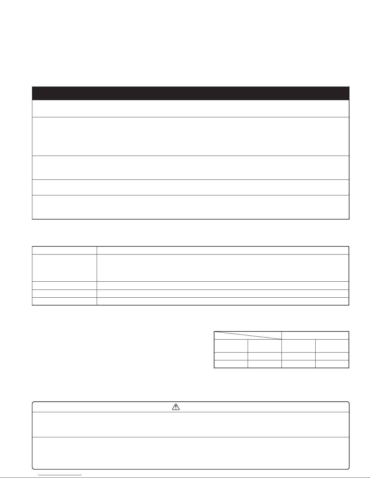
INSTALLATION DIAGRAM OF
INDOOR AND OUTDOOR UNITS
Fig. 2
[INDOOR UNIT]
6.7 cm or
over
Wall hook bracket
6.5 cm or over
5 cm or over
(Wall cap)
Fig. 1
3Rear piping
1Right piping
2Bottom piping
4Left-bottom
piping
5Left-rear piping
Connection Cord
Conform to Type245 IEC57
[OUTDOOR UNIT]
10 cm or over
60 cm or over
10 cm or over
30 cm or over
30 cm or
over
Fig. 3
54 cm
32 cm
150 cm or over
Drain hose
Outdoor unit bottom
230 cm or
over
Front panel
*The filters come out
of the front of the
indoor unit.
Indoor unit
housing
Remote
control unit
Remote
control unit
holder
6Left piping
INDOOR UNIT
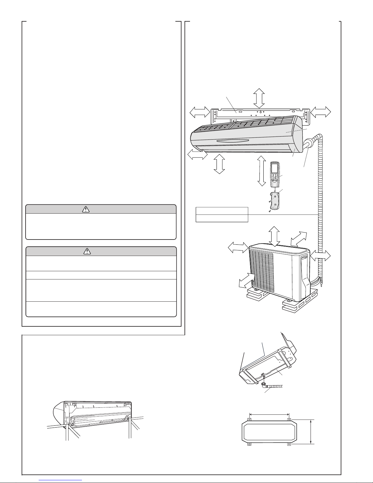
CUTTING THE HOLE IN THE WALL FOR THE CONNECTING PIPING
(1) Cut a 65 mm diameter hole in the wall at the position shown in (Fig.
4).
(2) When cutting the wall hole at the inside of the installation frame, cut
the hole within the range of the left and right center marks 40 mm
below the installation frame.
When cutting the wall hole at the outside of the installation frame,
cut the hole at least 10 mm below over.
(3) Cut the hole so that the outside end is lower (5 to 10 mm) than the
inside end.
(4) Always align the center of the wall hole. If misaligned, water leakage
will occur.
(5) Cut the wall pipe to match the wall thickness, stick it into the wall cap,
fasten the cap with vinyl tape, and stick the pipe through the hole.
(The connection pipe is supplied in the installation set.) (Fig. 4)
(6) For left piping and right piping, cut the hole a little lower so that drain
water will flow freely. (Fig. 4)
INSTALLING THE WALL HOOK BRACKET
(1) Install the wall hook bracket so that it is correctly positioned horizon-
tally and vertically. If the wall hook bracket is tiled, water will drip to
the floor.
(2) Install the wall hook bracket so that it is strong enough to withstand
the weight of an adult.
● Fasten the wall hook bracket to the wall with 8 or more screws through
the holes near the outer edge of the bracket.
● Check that there is no rattle at the wall hook bracket.
FORMING THE DRAIN HOSE AND PIPE
WARNING
If the wall pipe is not used, the cord interconnecting
the indoor and outdoor units may touch metal and
cause electric leakage.
CAUTION
Install the wall hook bracket horizontally and
perpendicularly.
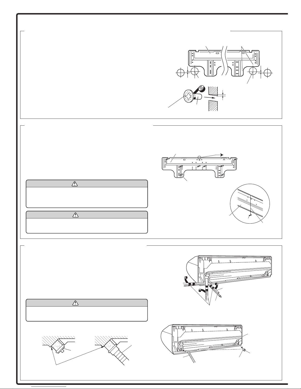
[Rear piping, Right piping, Bottom piping]
● Install the indoor unit piping in the direction of the wall hole and bind
the drain hose and pipe together with vinyl tape. (Fig. 6)
● Install the piping so that the drain hose is at the bottom.
● Wrap the pipes of the indoor unit that are visible from the outside
with decorative tape.
[For Left rear piping, Left piping]
Interchange the drain cap and the drain hose.
CAUTION
After removing the drain hose, do not forget to install
the drain cap.
Fig. 4
Lower
Centering marks
Fasten with
vinyl tape
(Wall cap)
(Wall pipe)
(Inside) Wall (Outside)
Fig. 5
Wall hook bracket
Leveling method
Hang weight
from here.
Fig. 6
Right outlet
Piping (on top)
Drain hose (on bottom)
Rear outlet
Bind with vinyl tape
Drain capDrain hose
Lower
65 mm hole
Insert the drain cap and drain hose
until it butts against the drain port.
Drain cap
Indoor unit
drain hose
65 mm hole
Tapping screw
(size: large; quantity: 8)
Wall hook
bracket
String
Wall hook bracket
Weight
Bottom outlet
Remove the drain
cap by pulling at
the projection at
the end of the cap
with pliers, etc.
For left outlet
piping, cut off the
piping outlet
cutting groove
with a hacksaw.
10 mm or
over
 Loading...