

Page 1
LIMITED TWO MONTH CONSUMER WARRANTY AND ONE YEAR CO NS UM ER WA RR AN TY
WHE N PURC HAS ED AND INSTALLED F ROM AUTHO RIZED ORION D EALER
Electronics Limited Warranty
Please keep your original bo x. Orion wa rr an ts th is produc t t o b e f re e fr om defec ts in ma te ri als and wo rk ma ns hi p
under normal use for a pe riod of TWO (2) mont hs f rom th e dat e of origi nal purc hase rece ipt . When
purchased and installed from an AUTHORIZ ED OR IO N d ea ler i t i s w ar ra nt ed for a pe ri od of ON E (1 ) Year f ro m
the date of the or ig inal pur ch as e r ec ei pt.
The ORIGINAL Receipt m us t b e provid ed fo r all c la ims. Sho ul d s er vi ce be nece ss ar y u nd er this warr an ty fo r a ny
reason due to manufacturing de fe ct or mal fu nc ti on du ring the w ar ra nt y p eriod.
ORION will repair or replace (at its di sc re ti on ) t he defec ti ve mer ch andise w it h e qu iv al ent merc ha nd is e w it h
equivalent merchandise at no ch ar ge. Warr an ty re pl ac ements m ay ha ve co sm etic scra tc he s o r b lemishe s.
Discontinued products may be re pl aced wit h m or e c ur re nt equiva le nt pr od uc ts.
This warranty is valid o nl y t o t he origina l purc ha se r a nd is non -t ra ns fe rable to any ot he r person or par ty . A ny
applicable implied warranties are limited i n d ur at io n t o a per iod of th e e xp re ss warrant y p ro vi de d h erein
beginning with the date of the original pu rc ha se at retail, an d no wa rr an ties, wh et he r e xp re ss or implie d,
shall apply to this pr od uct ther ea ft er . S om e states do not al low limi ta ti on s o n im plied wa rr an ti es ; t herefor e
these exclusions may not ap pl y to you. Th is warranty gi ve s y ou sp ecific l eg al rig ht s; ho wever yo u m ay hav e
other rights that vary fr om state to st at e.
What to Do if you need Warranty or Service
Defective merchandise should be r et ur ne d to your lo ca l auth or ized ORI ON de al er fo r warran ty ser vi ce .
Assista nc e l oc at in g an a ut ho ri ze d dealer ca n b e f ou nd at the p ro du ct s m ai n website ww w. or io nc araudio .c om
or by contacting ORION di re ctly at 1 -8 55 -4 75 -6 048.If i t b ec om es necessa ry fo r yo u to retu rn DE FE CT IV E
merchandise directly to ORION, ca ll the ORIO N C us to me r Care nu mb er at 1- 85 5-475-6 04 8 fo r a Return
Merchandise Authorization (RMA) nu mb er. Pack ag e a ll def ective ite ms in th e or iginal c on ta in er or in a packa ge
that wil l p re ve nt sh ipping dama ge . T he shippin g a dd re ss and instructions will be given to yo u by our cust om er
care representative upon their i ss ui ng the RMA numb er .
The RMA number must be cl ea rl y m ar ked on the ou ts id e o f th e packag e. Pl ea se return only de fe ct iv e compon ents. The return of f un ctionin g i te ms in cr eases yo ur ret ur n f reight c ha rg es . N ON - DE FECTIVE it em s w il l n ot be
exchanged.You will be conta ct ed by cu st omer care ad vi si ng yo u of such sit ua ti on s, an d produc t will be re turned
to you upon your pa ym ent of fr ei gh t c ha rg es for t he re tu rn of such prod uc t b ac k t o yo u.
Include a c op y o f th e o riginal re ce ip t w ith th e PURCHA SE DATE clearly visible, and a ROOF of PURCHASE
statement listing the CUSTOMERS NAME, DE AL ER 's NA ME and INVOI CE nu mb er , a nd prod uc t p ur ch ased.
Warranty expiration on i te ms without ROOF of PURCHASE wil l be deter min ed from the typ e of s ale
and manu fa ct ur in g d ate code . FREI GH T o n d ef ectives pr od uc ts re turned must be PR EPAID by you or y ou r
authorized dealer; items sent fr ei ght coll ec t, or CO D will be R EF US ED .
What is not covered?
The warranty is valid on ly if the pr od uc t is us ed for the purp os e f or wh ich it w as de si gn ed and does NOT CO VE R
the foll ow in g;
Damage due to improper in st allatio n a nd so un d s ettings , exce ss iv e o r insuff ic ie nt vo ltage spike s,
and use of inferior lo w g rade wir in g.
Subsequent Damage to other co mp onents
Damage c au se d b y e xp osure to moist ur e, ex ce ss ive heat , chem ic al cl eaners, an d/ or UV Rad ia ti on.
Damage t hr ou gh ne gl igence, mi su se , acci de nt or abuse . R ep ea te d re turns fo r t he sa me da mage may b e
con sid ered a bus e.
Any cost or ex pe ns e rela ted to th e r em ov al or i nstalla ti on of pr od uct. No In st al la ti on Fee re im bu rs em en ts.
Items pr ev io us ly re paired o r modi fi ed by an y unauth or iz ed rep air faci li ty
Return s hi pp in g c os ts from ORIO N t o y ou on non -defect iv e i te ms
Product s w it h t am pe red or missi ng ba rc od e l abels
Product s r et ur ne d w ithout a Ret ur n M er ch an dise Aut ho ri za ti on (RMA ) n um be r
Fre igh t Dama ge
The cost of sh ip pi ng pro du ct to ORI ON , f ro m yo u t o Orion
Service pe rf or me d b y anyone other th an Or io n
Damage r el at ed to Acts of Nature, lightning, hur ri ca nes, flo od , t or na do es, and wild fi re s.
Product s S ol d o ut si de of United St at es ha ve NO WARRANTY ex pr es se d o r impli ed
How long will it ta ke ?
ORION strives to maintain a g oa l of 7 day s er vi ce fo r a ll electron ic s p ro du ct s (ampli fi er s, eq ualizer s , ele ct ro ni c
crossovers, etc.) returns. Delays may be incurred if lac k of repl ac em en t i nventory or pa rt s i s e nc ountere d.
Failure to follow these Steps may void you r w ar ra nt y. Any questions ca n b e d ir ec ted to the OR IO N C us to mer
Care Department at 1-855-475-6048.
5 CHANNEL AM PL IFIER S
ZO6000.5
4 CHANNEL AM PL IFIER S
ZO1500.4
ZO2000.4
ZO3000.4
ZO4000.4
ZO5000.4
ZO6000.4
2 CHANNEL AM PL IFIER S
ZO1000.2
ZO1500.2
ZO2500.2
ZO4500.2
MONOBLOCK CLASS D 1 O HM AMPLIFIERS
ZO3000.1D
ZO5000.1D
ZO8000.1D
Page 2
SPECIFICATION
CLASS D MONO 1 O HM CHANN EL
POWER DESCRIPTION
RMS Watts @ 4 O hm
Mono 14.4V
RMS Watts @ 2 O hm
Mono 14.4V
RMS Watts @ 1 O hm
Mono 14.4V
Watts Nominal
Max Music Power W at ts
Frequency Response
Signal Noise Ratio
Input Impedance
Input Sensitivity
T.H.D.
Subsonic
Low Pass Freq.
Bass Boost
Phase
Supply Voltage
Dimensions(mm)
ZO3000.1D
245
425
750
1500
3000
10Hz~400Hz(-3dB)
90dB
22K Ohm
150mV~5V
<0.05%
25Hz
15Hz-400Hz
0~+18dB
O O
0 / 180
11~15V DC
320x231.5x55.5
ZO5000.1D
400
780
1250
2500
5000
10Hz~400Hz(-3dB)
90dB
22K Ohm
150mV~5V
<0.05%
25Hz
15Hz-400Hz
0~+18dB
O O
0 / 180
11~15V DC
357x231.5x55.5 392x231.5x55.5
ZO8000.1D
600
1000
2000
4000
8000
10Hz~400Hz(-3dB)
90dB
22K Ohm
150mV~5V
<0.05%
25Hz
15Hz-400Hz
0~+18dB
O O
0 / 180
11~15V DC
TABLE OF CONTENTS
Table Of Contents......... ... ... ................. ... ... ... ................. ... ... ......... ......1
Introduction................................................................................. .......2
Installation Instructions...................................................................... .2
Record Your Serial Number and Da te. ... ... ................. ... ... ................. ... .. 2
Functions....................................................................................... 3~4
Operation ...........................................................................................5
Trouble Shooting.......................................................................... ...... 5
Precautions ........................................................................................6
Fuse Replacement.............................................................................. 6
Stereo Mode ...................................................................................7~8
Speakers Connections....................................................................9~13
Speaker Connections At Br idg ed............... ... ... ................. ... ... ... .....14~17
Bridged Mode.............................................................................. 18 ~20
Power Connection Le ads.............. ... ... ... ................. ... ... ................. ... . 21
Wiring Instructions............................................................................ 22
Operation .........................................................................................23
Interference ......................................................................................24
Specification ...............................................................................25~28
28
1
Page 3

INTRODUCTION
SPECIFICATION
Thank you for purc hasing ou r car audi o am plifi er. The se pow er ampli fier has b een
designed to provide high q uality pe rformanc e wi th min imu m
maintenance. However, it' s perform ance will onl y be as goo d as the care a nd
quality of components wi th w hich i s insta lled. We there fore advi se that you re ad
these instructions very ca ref ully t o fa milia riz e yo ursel f wi th the pro duct and i t's
features.
Before installing the p owe r ampl ifi er ple ase rea d this ins truct ion manual ca refully.
The instructions for mo unt ing an d co nnect ing the set ha ve t o be follo wed precisel y.
If neces sary, a service cente r should b e co nsulted.
All connection for DC powe r, s ignal inp ut and spe ake r outp uts can be car rie d out
easily and safely by wa y of RCA and screw ed termin als.
INSTALLATION INSTRUCTIONS
Please choose a mount ing place without a ny d irect wea ther infl uences. N ote that
the amplifier generates h eat so tha t a well venti lat ed place i s necessa ry.
According to your c ar' s cons tru ction the set can be mad e very car efully in ord er to
ensure the amplifier's f ull perfo rma nce an d relia bilit y.
Keep the wire connect ions as sh ort as pos sib le wit h sufficient length in
order to minimize pow er l osses and pro vide a hig her audio out put of the system.
For safety reasons rout e al l powe r and sp eaker wir ing by usi ng t he exitin g wire
channels.
To mi nimize da mage to the ca bles, tak e ca re tha t th ey do not p ass sharp edg ed
metal.
Lay all cables as far aw ay a s poss ibl e from the ign ition cab les, modu les in the
boot and under the key dashboar d, a s thes e cr eate inte rfe rence .
Add a fuse into th e (+) powe r ca ble in a di sta nce of not mor e than 30c m from the
positive battery pole.
Keep the length of the p ower wire s as short as p oss ible . It i s be tter to us e power
cables which are shor t and then lon ger sp eak er cab les .
In order to redu ce interf erence , p lea se pay att entio n to the wirin g instructio ns.
RECORD YOUR SERIAL NUMBER AND DATE
To en sure y our warra nty, p lea se rec ord th e fo llowi ng inf orm ation regar din g
your new amplifier.
Model:
Seri al Number :
Date of Purcha se:
Purc hased fro m:
FIVE CHANNEL
POWER DESCRIPTION
RMS Watts @ 4 O hm
Stereo 14.4V
RMS Watts @ 2 O hm
Stereo 14.4V
RMS Watts @ 4 O hm
Bridge 14.4V
Watts Nominal 4 TH Ch an ne l S ec tion
Max Power 4 T H C ha nnel Setio n
Frequency Response
Signal Noise Ratio
Input Impedance
Input Sensitivity
T.H.D.
Hi pass Freq.
RMS Watts @ 4 O hm
Mono 14.4V
RMS Watts @ 2 O hm
Mono 14.4V
RMS Watts @ 1 O hm
Mono 14.4V
Class D Section W at ts Nominal
Total A mp lifier W at ts Nomina l
Max Music Power W at ts
Frequency Response
Signal Noise Ratio
Input Impedance
Input Sensitivity
T.H.D.
Low pass Freq.
Bass Boost
Supply Voltage
Dimensions(mm)
ZO6000.5
100 X4
150 X 4
300 X 2
1200
2400
10Hz~36KHz(-3dB)
90dB
22K Ohm
250mV~5V
<0.05%
50Hz-4KHz
260
450
900
1800
3600
6000
10Hz~400Hz(-3dB)
90dB
22K Ohm
150mV~5V
<0.05%
15Hz-400Hz
0~+18dB
11~15V DC
527x231.5x55.5
2
27
Page 4
SPECIFICATION
FUNCTIONS
POWER DESCRIPTION
RMS Watts @ 4 O hm
Stereo 14.4V
RMS Watts @ 2 O hm
Stereo 14.4V
RMS Watts @ 4 O hm
Bridge 14.4V
Watts Nominal
Max Music Power W at ts
Frequency Response
Signal Noise Ratio
Input Impedance
Input Sensitivity
T.H.D.
Hi Pass Freq.
Low Pass Freq.
Bass Boost
Supply Voltage
Dimensions(mm)
TWO CHANNEL
ZO1000.2
70 X 2
125 X 2
250
500
1000
10Hz~36KHz(-3dB)
90dB
22K Ohm
250mV~5V
<0.05%
50Hz-400Hz
50Hz-400Hz
0/6/12dB
11~15V DC
237X231.5X55.5
TWO CHANNEL
ZO2500.2
225 X 2
315 X 2
625
1250
2500
10Hz~36KHz(-3dB)
90dB
22K Ohm
250mV~5V
<0.05%
50Hz-400Hz
50Hz-400Hz
0/6/12dB
11~15V DC
297X231.5X55.5
ZO1500.2
105 X 2
175 X 2
350
750
1500
10Hz~36KHz(-3dB)
90dB
22K Ohm
250mV~5V
<0.05%
50Hz-400Hz
50Hz-400Hz
0/6/12dB
11~15V DC
247X231.5X55.5
ZO4500.2
400X 2
630 X 2
1375
3750
4500
10Hz~36KHz(-3dB)
90dB
22K Ohm
250mV~5V
<0.05%
50Hz-400Hz
50Hz-400Hz
0/6/12dB
11~15V DC
450X231.5X55.5
ZO6000.5
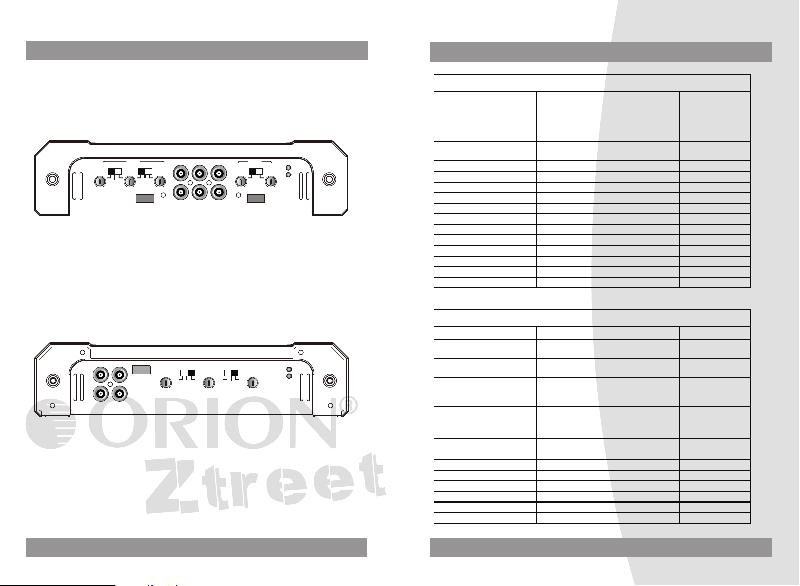
CH1 CH3
INPUT
ZO6000.5ZO6000.5
CH3/CH4
4KHz
4KHz
FULL
HPF
MODE
FULL
HPF
MODE GAIN
CH1/CH2
GAIN
+--+
CH3/CH4
Max
Min
HI INPUT
+--+
Max
Min
CH1/CH2
HPF
50Hz
50Hz
HPF
ZO3000.1D/ZO5000 .1D/ZO8 000.1D
LINE INPUT
PWR
PWR
LINE OUT
PRO
PRO
R
Max
Min
GAIN
L
O
O
180
0
25HzOFF
PHASESUB SONIC
Input Mode
Gain control
LPF / HPF contr ol
Mosfet power supply
1~5 Channel Power Amplifier
Sub Sonic control
Bass Boost control
Thermal protection
LED Power and Prote ction Indicator
Low Input and High Inp ut S elected
CH4CH2
15Hz 0dB
LPF
400Hz
BASS BOOST
HI INPUT
GAIN
Min
0dB
CH5CH5
BRIDGED
PWR
PRO
Max
REMOTE
+18dB
IN
OUT
R
+--+
L/R
CH5
L
400Hz 15Hz
BASS BOOST
LPF
+18dB
REMOTE
26
3
Page 5
FUNCTIONS
SPECIFICATION
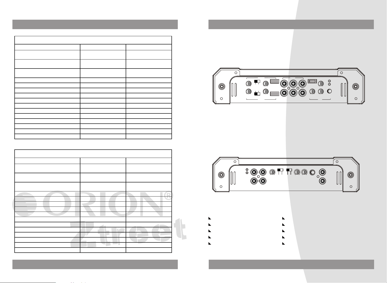
ZO1500.4/ZO2000. 4/ZO300 0.4/ZO4000.4/ZO500 0.4/ZO6 000.4
INPUT
CH3/CH4
MODE
BASS BOOST
LPF
HPF
FULLHPF
LPF
50Hz
50Hz
400Hz
12 6 0
400Hz
HI INPUT
+--+
CH3 CH4
GAIN
Max
Min
OUTPUT INPUT
CH4 CH2
CH1/CH2
MODE
CH2
GAIN
Max
Min
CH1CH3
CH1
CH1 CH2
FULL HPF
HI INPUT
+--+
PWR
HPF
PRO
50Hz
400Hz
ZO1000.2/ZO1500. 2/ZO250 0.2/ZO4500.2
OUTPUT
R
L
HI INPUT
+--+
R
LPF
50Hz 400Hz
MODE
FULL HPF
LPF
HPF
50Hz 400Hz
PWR
PRO
BASS BOOST
GAIN
L
Min
12120 6
Max
INPUT
R
L
POWER DESCRIPTION
RMS Watts @ 4 O hm
Stereo 14.4V
RMS Watts @ 2 O hm
Stereo 14.4V
RMS Watts @ 4 O hm
Bridge 14.4V
Watts Nominal
Max Music Power W at ts
Frequency Response
Signal Noise Ratio
Input Impedance
Input Sensitivity
T.H.D.
Hi Pass Freq.
Low Pass Freq.
Bass Boost
Supply Voltage
Dimensions(mm)
FOUR CHANNEL
ZO1500.4
75X 4
90 X 4
180 X 2
750
1500
10Hz~36KHz(-3dB)
90dB
22K Ohm
250mV~5V
<0.05%
50Hz-400Hz
50Hz-400Hz
0/6/12dB
11~15V DC
330X231.5X55.5
FOUR CHANNEL
ZO4000.4
175 X 4
250 X 4
500 X 2
2000
4000
10Hz~36KHz(-3dB)
90dB
22K Ohm
250mV~5V
<0.05%
50Hz-400Hz
50Hz-400Hz
0/6/12dB
11~15V DC
382X231.5X55.5
ZO2000.4
90 X 4
125 X 4
250 X 2
1000
2000
10Hz~36KHz(-3dB)
90dB
22K Ohm
250mV~5V
<0.05%
50Hz-400Hz
50Hz-400Hz
0/6/12dB
11~15V DC
ZO3000.4
125 X 4
190 X 4
380 X 2
1520
3000
10Hz~36KHz(-3dB)
90dB
22K Ohm
250mV~5V
<0.05%
50Hz-400Hz
50Hz-400Hz
0/6/12dB
11~15V DC
362X231.5X55.5 372X231.5X55.5
ZO5000.4
185 X 4
315X 4
625 X 2
2500
5000
10Hz~36KHz(-3dB)
90dB
22K Ohm
250mV~5V
<0.05%
50Hz-400Hz
50Hz-400Hz
0/6/12dB
11~15V DC
ZO6000.4
250 X 4
375 X 4
750 X 2
3000
6000
10Hz~36KHz(-3dB)
90dB
22K Ohm
250mV~5V
<0.05%
50Hz-400Hz
50Hz-400Hz
0/6/12dB
11~15V DC
392X231.5X55.5 512X231.5X55.5
4
25
Page 6

INTERFERENCE
OPERATION
All cables are sour ces of int erferenc e. T he pow er cable and RC A aud io c able
are very prone to in terferen ce; the remot e cabl es a re less pr one . There is ofte n
interference caused by t he g enera tor (pipi ng) , ig nitio n ( c racki ng ) or other car
electronic parts. Most o f th ese pr obl ems can be eli minat ed b y correct and careful
cabling. In doing so, t hese are t he f ollow ing guide lin es :
Use only a scre ened audi o cable for th e wiri ng b etw een " l ow l eve l in " of th e
amplifi er and RCA o r DI N outp ut o f th e radi o .
Lay the signal, speak er and pow er c ables sep arate ly w ith enoug h distanc e
from one another a nd a lso fr om e ach other car cab le. lf not possible , you can
lay the circuit and gro und ca ble tog ether wit h the seri al c ables . Audio and
speaker cable should b e as far away f rom these as p oss ible. The REM cable to
the automatic antenna o utp ut of t he r adi o can b e laid t ogeth er w ith the si gnal
cables.
Avoid ground loop s by layin g the ground w iring of all c omponent s to a cent er
point in a star -like way. You can find th e best cen tral point in measurin g th e
voltage directly at t he b atter y. Now compare this vo ltage val ue w ith th e ch osen
ground point and the ( +) termin al o f the a mpl ifier. lf the meas ure d volt age in
only less different you've found the c orr ect ce ntr al.Other wise you h ave to loo k
for another point. Y ou shou ld measur e with the ign ition bei ng s witch ed o n and
additionally switched on o the r elec tro nics ( rea r wi ndow h eat ing and li ght ).
If there are pi cku ps from ex ternal elect rical sou rces i nto the speak er cables ,
divide the core lead s and twis t th em tog eth er.
If there are no ise s from the car elect ron ics. Add an interference s uppressi on
choke to the powe r wiring .
If there are hum ing noises, u se t hicke r gr ound c abl es or add f urther groun d
cables to the chas sis.
To re duce cont act resis tance and bad and loose con tacts , pl ease tin t he cable
ends or use multi c ore cable end s, spa de t ermin als or o thers . Go ld Plated
spade terminal are fre e of corrosio n an d have the low est co nta ct res ist ance.
Should all these measur es to with out any su cce ss. th e use of a ground l oop
isolato r may solv e th e prob lem .
GND(-)=GROUND CONNECTION
Connect the GND te rminal to the cha ssis grou nd of your c ar and take care o f best
electric and mechanic co ntact. In doing s o, drill a hole in to the car c hassis near
the amplifier then re move colo r, d irt or any other subs tance fro m the gr oun d poin t.
After that fasten th e cabl e en d with a dded ring termin al b y usin g a screw. Ensure
that the ground co nnection is as short as pos sible a nd t hat th e cable dia meter is
sufficient ( min 4 mm" ) . Route the ground cab les fr om t he radio and al l oth er
equipment parts. like eq ualizer. active cross ove r netw ork or ot her am pli fiers , to
the same ground po int.
+12V=POWER SUPPLY
Connect the +12V te rminal to the positive p ole of t he batter y with a lea d cabl e
and add a fu se in t o the power cable i n a d istan ce of not mo re then 30 c m from t he
battery. The lea d cables' s diame ter shoul d be at leas t 4 mm' for a length of 3 m
and 6 mm" fo r a len gth of 6m.
REM(ON/OFF)REMOTE CONTROL
Connect the REM te rminal to the aut omatic an tenna con nector of y our ca r rad io.
Now when turning on and off your car radio . the ampl ifier a uto matic all y swit che s
ON and OFF. A cab le dia met er of 0. 5mm is suf ficient.
FUSE
The amplifier is eq uipped wi th a plu g-i n auto fus e prote cti ng the set agains t fa ult
conditions. Do not us e a fuse wit h a hig her value a nd n ever bridg e the f use over ,
as this may le ad to i rre parab ili ty damage s o that ant any c laim for wa rra nty is
denied.
TROUBLE SHOOTING
No Function:
The connection cable is not conne cted correctly ( = terminal BATT/GND /REM).
Ensure that all con nections and mecha nic contac t and that the jac ket has bee n
removed. The fuse is defecti ve-pay at tention to the corre ct valu e of a new fu se!
No Sound:
Speaker cable or sp eaker plu g are not connect ed correc tly.
No Sound /Red LE D Prot ect ion Sh ine s:
The plus and mi nus wires of the spea ker cable have co nta ct, th us el imina te t he
short circuit. If yo u use a 2 Ohm spe aker in ste reo mode, a 4 Ohm speak er in
bridge mode or tr i-mode an d the se is overloaded, then tu rn the gai n contr ol t o
"min " until th e oper ati on is free of trou ble.
Poor Sound Quality ( D istor tio ns ):
The speakers are ov erloaded , therefo re turn dow n th e volu me level and ch eck
the volume control po sitions.
No Stereo Sound An d A Weak Ba ss:
Speaker cables (+) an d (-) are mixed up , un it w ire d out of phase.
t
24
5
Page 7

PRECAUTIONS
OPERATION
This unit is desi gned for n egative g rou nd 12V DC o per ation onl y.
Use speakers with an im pedance o f 2 o r 4 O hms ( 2 to 4 Ohm wh en used as
brid gin g ampl ifi er )
Avoid installing the u nit where :
-It would be subj ect to hig h temperatur es, such a s from direct sunlight or h ot air
from the heater.
-It would be expo sed to rai n or moisture .
-It would be subj ect to dus t or dirt.
If your car is pa rked in direc t sunligh t and there is a consi derab le r ise in
temperature inside the car, allow the uni t to cool off before op eration.
When installing the unit horizont ally, be sure not to cov er t he hea tsi nk fin s with
the floor carpet.
If this unit is pl aced too clos e to the car ra dio, an inter fer ence m ay o ccur. In this
case, separate the ampl ifier fro m the car radi o.
This power amplifier empl oys a prot ection circu it to prot ect the trans istors an d
speakers if the ampl ifier m lfunctions. Do not attem pt to test the protecti on
circuits by covering the h eatsink o r connecting improper loads.
Do not use the u nit with a wea k auto b atter y as its optim um p erfor man ce
depends on a norm al batter y supply volt age.
For safety reasons, keep the volum e of your car audi o system m oderate so th at
you can still hear normal tr affic sounds outside yo ur car .
a
FUSE REPLACEMENT
If the fuse blow s, check t he p ower c onn ectio n an d re place the f us e. If t he f use
blows again after repl acement, there may be a n inte rna l ma lfunc tio n. In t his case,
consult your dealer.
WARNING:
Use the specified ampe rage fuse . Use of a high er a mpera ge f use may cause
serious damage.
After the amplifier has be en ins tal led and all connecti ons have be en m ade carefu l
-lyand securely, turn the radio on so that t he amplif ier is switche d on automa tic ally.
After a short power -on pe rio d, the ampl ifier rea ches its full p erforman ce.
Now turn up the vo lume s low ly using th e volume contr ol of t he radio. If th ere is no
sound or only a dist orted rep lay, switch off the ra dio immed iat ely, the amplifier wil l
also switch off automat ically, and check if al l conn ect ions h ave been made c orrectly.
POWER=LED POWER INDICATOR
After the orderly conne ction of t he three po wer termi nals, the L ED i ndica tor shines
green and goes out wi th off .
PROTECT =LED PROTECTION INDICATOR
This set is e quipp ed w ith an overloa d protect ion, imme diately upon o verloadi ng
due to short circu it or m uch increased temperat ure the ove rlo ad pro tec tion i s
activated and the red LE D indi cat or is shi ning. Thr ough this t he amp lif ier is
protected against damage. In cas e of the the rmal prot ection a ce rta in sho rt cooling
time must be allow ed aft er w hich the am plifier a utomatic ally resum es o perat ion .
LEVEL CONTROL
The input level contr ol all ows the system to work wel l wi thin a wide range of outpu t
level. Choose the adjus tment in t he way that you achiev e a s ound m ost possib ly
without any distortion. as a gu ideli ne the followi ng proced ure is re comme nde d:
If you use sever al amp lif ier, the adjustm ent has to b e ma de for each set separatel y,
tune up the volum e of yo ur car radio to 2/3 o f the maxim um volume .
Now turn the gain c ontro l of the amplif ier from " Min " to " Max " dire ction unt il you
can hear distortions. Then t urn th e le vel con trol a lit tle back to " Min ". T he gain
control adjustment is finis hed no w.
Attention! If you use 2 Ohm spe akers in st ere o mode . Tri -mode or 4 Ohm spe akers
in bridge mode and th e over loa d protecti on is trig gered, tur n the gain control t o
" Min " direc tion, unt il the oper ation is f ree of trou ble.
HIGH PASS AND LOW PASS CONTROLS
This amplifier has controls for making good s ound
combination.
high pass and low pa ss
PROTECTION CIRCUIT:
This amplifier is prov ided with a pr otection circuit w hich oper ate s in th e follo wing
cases when:
the unit is o verhe ate d.
the spea ker termi nals are s hor t circ uit ed.
6 23
Page 8

WIRING INSTRUCTIONS
POWER CONNECTION
The battery terminal (+12 V) m ust be con nected di rectly to the positive terminal of
the vehicle battery to pr ovi de an adeq uate volt age sourc e and minimiz e noise.
Connecting the battery term ina l lead to a ny other p oint (such as the fuse bloc k )
will reduce the powe r ou tput a nd m ay cause n oise and dist ortion. U se o nly #1 0
gauge or thicker (sma lle r gaug e # ) wire for this lead and conn ect it to the t erminal
of the battery afte r all othe r wiring is co mpleted.
GROUND CONNECTION
The ground terminal (GND ) co nnect ion is a lso criti cal to the cor rect oper ation o f
the amplifier. Use a wire o f the s ame gau ge as the powe r connect ion ( #1 0 or thicker)and connect it betw een the gr oun d te rminal (G ND ) of the amp lifier and a
metal pa rt of the vehi cle close to t he m ounti ng loca tion. Thi s wire sh ould be as
short as possible and a ny p aint or rust a t the groundi ng point shou ld b e scra ped
away to provide a cle an m etal surf ace to whi ch the e nd of th e grou nd w ire can be
screwed or bolted .
REMOTE TURN-ON CONNECTION
The amplifier is turn ed o n by apply ing +12V t o the re mote turn -on ter minal (RE M).
The wire lead to th is termin al s hou ld be c onn ected to the " Auto-Ant enna " l ead
from the car ster eo which w ill pro vide t he + 12V only when the car stere o is tur ned
on. If the car s tereo doe s not pr ovide an Auto -Antenna " lead, the re mot e turn -on
lead may be wire d to an " Acces sor y " or "Radio " terminal in t he c ar's f use blo ck.
This will turn the a mplifier on a nd o ff with the ign ition k ey, regardles s of wheth er
the car stereo is on or o ff. The rem ote turn- on l ead does not c arry la rge cu rre nts.
So #20 gauge wire m ay be us ed for thi s applicatio n.
SPEAKER CONNECTIONS
Depending on the type and numbe r of spe akers use d with the amp lifier, wire them
to the speaker termin als as per the app ropriate wiring diagr am. For mo st
applications #18gauge wire shoul d be used for the s peaker leads but in n o case
thinner than #20 gaug e. F or lea ds in ex cess of 10 fee t # 1 6 ga uge is recomm ended. When wiring the s pea kers, pay car eful atte ntion to the p olarity o f the te rminals on the spea kers and m ake cer tain t hey corre spo nd t o the pola rity of the corresponding terminals on the a mpl ifier . Do not ground any sp eak er lea ds to th e
chassis of the vehic le.
INPUT CONNECTIONS
This amplifier features low- lev el inp ut c apabi lit y.
If the car ster eo does no t provi de low -le vel ou tpu ts, the ampli fier may be co nne c
-ted via the speak er (high- level) ou tputs f rom the st ereo with a AUTOCRAFT line
converter.
STEREO MODE
ZO1500.4/ZO2000. 4/ZO300 0.4/ZO4000.4/ZO500 0.4/ZO6 000.4
INPUT
CH3/CH4
MODE
BASS BOOST
LPF
HPF
FULLHPF
LPF
50Hz
50Hz
400Hz
12 6 0
400Hz
HI INPUT
+--+
CH3 CH4
GAIN
Max
Min
ZO1000.2/ZO1500. 2/ZO250 0.2/ZO4500.2
INPUT
R
L
R
HI INPUT
OUTPUT
+--+
R
GAIN
L
Min
R
L
L
OUTPUT INPUT
CH4 CH2
BASS BOOST
12120 6
Max
CH1CH3
LPF
50Hz 400Hz
CH2
GAIN
Max
Min
CH1
CH1 CH2
CH1 CH2CH4 CH3
CAR STEREO
MODE
FULL HPF
LPF
50Hz 400Hz
CAR STEREO
CH1/CH2
MODE
FULL HPF
HI INPUT
+--+
HPF
PWR
HPF
PRO
50Hz
400Hz
PWR
PRO
22 7
Page 9

STEREO MODE
ZO6000.5
POWER CONNECTION LEADS
POWER
CH1 CH3
CH1
INPUT
CH4CH2
ZO6000.5ZO6000.5
CH3
CH3/CH4
FULL
HPF
MODE
FULL
HPF
MODE GAIN
CH1/CH2
GAIN
+--+
CH3/CH4
Max
Min
HI INPUT
+--+
Max
Min
CH1/CH2
CH2
HPF
50Hz
4KHz
4KHz
50Hz
HPF
CAR STEREO
ZO3000.1D/ZO5000 .1D/ZO8 000.1D
LINE INPUT
PWR
PWR
LINE OUT
PRO
PRO
R
Min
GAIN
L
O
0
25HzOFF
Max
PHASESUB SONIC
L
R
180
CH4
O
CH5
15Hz 0dB
400Hz
LPF
R
L
L
CH5
+18dB
BASS BOOST
HI INPUT
+--+
R
L/R
LPF
REMOTE
400Hz 15Hz
GAIN
Max
Min
+18dB
0dB
BASS BOOST
CH5CH5
BRIDGED
PWR
PRO
REMOTE
IN
OUT
CAR STEREO
HEAD UNIT
REM
+12V
( +12V)
REMOTE OUT
FUSE
++
BATTERY
GND
DC 12V
to a metal part of car
NOTES ON THE POWER SUPPLY :
Connect the +12V po wer input lea d on ly aft er a ll o ther l ead s have bee n
connected.
Be sure to conn ect the gr ound wire of t he u nit se cur ely to a me tal part of th e car.
A lose con nection m ay cause a mal funct ion of t he amp lif ier.
REM: The unit is turned on b y applyin g +1 2 Volts to thi s termina l. T his te rmi nal
does not draw heav y cu rrent lik e th e Powe r Terminals s o a thi nne r
connecting wire is a cce ptabl e. S tandard 1 8 GA UGE is fin e and the s tandard
color is yellow .lf t he radio i s eq uippe d wi th a Power Antenna control wire, it can
drive this terminal . If t he P ower A nte nna wire i s al ready in u se, you can st ill
splice into it. W ith this m eth od, the un it w ill turn o n au tomat ica lly with t he radio.
Use the power supp ly lead wi th a fuse a tta ched whos e va lue is the same as
original fuse.
Place the fuse i n th e power suppl y lead as c los e as po ssi ble to the car battery .
During a full powe r operati on, maxim um c urren t wi ll run thr ough the s ystem
Therefore, make sure t hat th e le ads to be c onn ected to t he +12V and GN D
termina ls of the u nit respe cti vely m ust be larger than 10-Gaug e ( AWG.10).
8
21
Page 10

BRIDGED MODE
SPEAKERS CONNECTIONS
ZO1500.2/ZO2500. 2
MONO SPEAKER
LEFT
ZO4500.2
LEFT
SPEAKER OUTPUT
MONO SPEAKER
ZO6000.5
4~8Ohm
BRIDGED
SPEAKER OUTPUT
BRIDGED
RIGHT
4~8Ohm
RIGHT
ZO1500.2:30AX2
ZO2500.2:40AX2
FUSE
+12V
POWER INPUT
REM GND
+12V
POWER INPUT
ZO4500.2:200A
REM GND
ZO1500.4/ZO2000. 4/ZO300 0.4
Ch1
SPEAKER
2~4Ohm
CH1 CH2
SPEAKER OUTPUT
CH3 CH4
BRIDGED
Ch3
SPEAKER
2~4Ohm
ZO4000.4
Ch1
SPEAKER
2~4Ohm
CH1 CH2
SPEAKER OUTPUT
FUSES
SPEAKER
2~4Ohm
FUSES
Ch4
SPEAKER
2~4Ohm
SPEAKER
2~4Ohm
Ch2
Ch2
REM GND
+12V
POWER INPUT
ZO1 50 0. 4:30A x2
ZO2 00 0. 4:35A x2
ZO3 00 0. 4:40A x2
REM GND
+12V
CH1 CH2
SPEAKER OUTPUT
CH3 CH4
BRIDGED
MONO SPEAKER
4~8Ohm
CH5
SPEAKER OUTPUT
MIN 1
+12V
POWER INPUT
REM
GND
Ch3
SPEAKER
2~4Ohm
CH3 CH4
BRIDGED
ZO6000.5:150A
20 9
40A X 3
Ch4
SPEAKER
2~4Ohm
POWER INPUT
Page 11

SPEAKERS CONNECTIONS
BRIDGED MODE
ZO5000.4
Ch1
SPEAKER
2~4Ohm
Ch3
SPEAKER
2~4Ohm
ZO6000.4
Ch1
SPEAKER
2~4Ohm
SPEAKER OUTPUT
SPEAKER OUTPUT
CH1 CH2
CH3 CH4
BRIDGED
CH1 CH2
CH3 CH4
BRIDGED
FUSES
40A X 4
Ch2
SPEAKER
2~4Ohm
Ch4
SPEAKER
2~4Ohm
Ch2
SPEAKER
2~4Ohm
REM GND
+12V
POWER INPUT
REM GND
+12V
POWER INPUT
ZO5000.4
ZO6000.4
ZO1000.2
MONO SPEAKER
4~8Ohm
CH1 CH2
SPEAKER OUTPUT
CH3 CH4
MONO SPEAKER
4~8Ohm
CH1 CH2
SPEAKER OUTPUT
CH3 CH4
MONO SPEAKER
4~8Ohm
MONO SPEAKER
BRIDGED
BRIDGED
4~8Ohm
FUSES
40A X 4
ZO6000.4:200A
REM GND
+12V
POWER INPUT
REM GND
+12V
POWER INPUT
Ch3
SPEAKER
2~4Ohm
10
Ch4
SPEAKER
2~4Ohm
ZO6000.4:200A
BRIDGED
LEFT
SPEAKER OUTPUT
RIGHT
FUSE
40A
19
REM GND
+12V
POWER INPUT
Page 12

BRIDGED MODE
SPEAKERS CONNECTIONS
ZO1500.4/ZO2000. 4/ZO300 0.4
MONO SPEAKER
4~8Ohm
CH1 CH2
SPEAKER OUTPUT
CH3 CH4
BRIDGED
MONO SPEAKER
4~8Ohm
ZO4000.4
MONO SPEAKER
4~8Ohm
FUSES
+12V
POWER INPUT
ZO1 50 0. 4:30A x2
ZO2 00 0. 4:35A x2
ZO3 00 0. 4:40A x2
REM GND
ZO1000.2
LEFT
SPEAKER
2~4Ohm
ZO1500.2/ZO2500. 2
LEFT
SPEAKER
2~4Ohm
BRIDGED
LEFT
SPEAKER OUTPUT
RIGHT
FUSE
40A
RIGHT
SPEAKER
2~4Ohm
+12V
POWER INPUT
RIGHT
SPEAKER
2~4Ohm
REM GND
CH1 CH2
SPEAKER OUTPUT
CH3 CH4
BRIDGED
MONO SPEAKER
4~8Ohm
18
FUSES
40A X 3
REM GND
+12V
POWER INPUT
BRIDGED
LEFT
RIGHT
SPEAKER OUTPUT
ZO1500.2:30AX2
ZO2500.2:40AX2
11
FUSE
REM GND
+12V
POWER INPUT
Page 13

SPEAKERS CONNECTIONS
SPEAKERS CONNECTIONS AT BRIDGED
ZO4500.2
LEFT
SPEAKER
2~4Ohm
ZO6000.5
BRIDGED
LEFT
SPEAKER OUTPUT
RIGHT
RIGHT
SPEAKER
2~4Ohm
REM GND
+12V
POWER INPUT
ZO4500.2:200A
ZO8000.1D
AMP 1
MASTER
PWR
PWR
PRO
PRO
CAR STEREO
LINE OUT
LINE INPUT
R
Max
Min
GAIN
L
25HzOFFO0
O
180
15Hz 0dB
400Hz
BASS BOOST
PHASESUB SONIC
LPF
BRIDGED
+18dB
REMOTE
IN
OUT
SPEAKER OUTPUT
CH1 CH2
CH3 CH4
BRIDGED
CH5
SPEAKER OUTPUT
MIN 1
12
REM
+12V
POWER INPUT
ZO6000.5:150A
GND
AMP 2
SAVEL
LINE INPUT
PWR
PWR
LINE OUT
PRO
PRO
R
Max
Min
GAIN
L
O
O
180
0
15Hz 0dB
25HzOFF
400Hz
BASS BOOST
PHASESUB SONIC
LPF
BRIDGED
+18dB
REMOTE
IN
OUT
17
Page 14

SPEAKERS CONNECTIONS AT BRIDGED
SPEAKERS CONNECTIONS
ZO8000.1D
AMP 1
4~8Oh m
SPEAKER OUTPUT
MIN 1
FUSES
30A X 4
BATTERY
DC 12V
REM GND
+12V
POWER INPU T
To a metal
part of car
ZO3000.1D/ZO500. 1D
MONO S PE AK ER
1~4Ohm
+ +
SPEAKER OUTPUT
MIN 1
ZO8000.1D
MONO S PE AK ER
1~4Ohm
+ +
FUSES
+12V
ZO3 00 0. 1D:30 Ax 3
ZO5 00 0. 1D:35 Ax 3
REM GND
POWER INPU T
AMP 2
SPEAKER OUTPUT
MIN 1
FUSES
30A X 4
16
REM GND
+12V
POWER INPU T
SPEAKER OUTPUT
MIN 1
FUSES
30A X 4
13
REM GND
+12V
POWER INPU T
Page 15

SPEAKERS CONNECTIONS AT BRIDGED SPEAKERS CONNECTIONS AT BRIDGED
ZO3000.1D/ZO500. 1D ZO3000.1D/ZO500. 1D
AMP 1
4~8Oh m
SPEAKER OUTPUT
MIN 1
FUSES
ZO3 00 0. 1D:30 Ax 3
ZO5 00 0. 1D:35 Ax 3
BATTERY
DC 12V
REM GND
+12V
POWER INPU T
To a metal
part of car
AMP 1
MASTER
PWR
PWR
PRO
PRO
CAR STEREO
LINE OUT
LINE INPUT
REMOTE
BRIDGED
IN
OUT
R
Max
Min
GAIN
L
25HzOFFO0
O
180
PHASESUB SONIC
15Hz 0dB
400Hz
BASS BOOST
LPF
+18dB
AMP 2
SPEAKER OUTPUT
MIN 1
14
FUSES
REM GND
+12V
POWER INPU T
AMP 2
SAVEL
LINE INPUT
PWR
PWR
LINE OUT
PRO
PRO
R
Max
Min
GAIN
L
O
O
180
0
25HzOFF
PHASESUB SONIC
15Hz 0dB
400Hz
BASS BOOST
LPF
+18dB
REMOTE
BRIDGED
IN
OUT
15
 Loading...