

Orion XTRPRO102D, XTRPRO122D, XTRPRO124D, XTRPRO152D, XTRPRO154D Owner's Manual
...
Subwoofer
MODEL
XTRPRO102D
XTRPRO104D
XTRPRO122D
XTRPRO124D
XTRPRO152D
XTRPRO154D
OWNER'S MANUAL


TABLE OF CONTENTS
English . . . . . . . . . . . . . . . . . . . . . . . . . . . . . . . . . . . . . . . . . . . . . . . . . . . . . . . . . . . . . . .
Français . .. . . . . .. . .. . .. .. . . .. . .. . .. .. . . .. . .. . .. .. . . .. . .. . .. .. . . .. . .. .
Español. . . . . . . . . . . . . . . . . . . . . . . . . . . . . . . . . . . . . . . . . . . . . . . . . . . . . . . . . . . . . .35
Deutsch . .. .. . . .. . .. . .. .. . . .. . .. . .. .. . . .. . .. . .. .. . . .. . .. . .. .. . . .. . .. .45
Italiano. . . . . . . . . . . . . . . . . . . . . . . . . . . . . . . . . . . . . . . . . . . . . . . . . . . . . . . . . . . . . .
Português . .. . . .. . .. . .. .. . . .. . .. . .. .. . . .. . .. . .. .. . . .. . .. . .. .. . . .. . .. . 65
Introduction . . . . . . . . . . . . . . . . . . . . . . . . . . . . . . . . . . . . . . . . . . . . . . . . . . . . . . .
PracticeSafeSound™ ................................................
What'sinthebox.. .................................................
Tools of the Trade . . . . . . . . . . . . . . . . . . . . . . . . . . . . . . . . . . . . . . . . . . . . . . . . . . .
Installation .........................................................
Finding Speaker Mounting Locations . . . . . . . . . . . . . . . . .. . . . . . . . . . . . . . . . . . . .
Features ..........................................................
Wiring Configurations . . . . . . . . . . . . . . . . . . . . . . . . . . . . . . . . . . . . . . . . . . . . . . . . .4
Specifications ......................................................
EnclosureRecommendations...........................................
Warranty ................................ .................. Backcover
2
55
.2
14
18
1
5
1
1
2
2
2
3
INTRODUCTION
Thank you for your purchase of the Orion XTRPRO Subwoofers. These woofers
represent a combination of incredible performance and value. We at Orion strive to
give you the latest up to date information about this product. What we can’t give
you with the manual is personal installation or technical experience. If you have
questions concerning the use or application of this product please refer to the nearest
Orion dealer for assistance, visit www.orioncaraudio.com, or call the technical support
hotline at
the features and specifications are subject to change without notice.
1-855-475-6048
As we are always finding new ways to improve our product,
PRACTICE SAFE SOUND™
Continuous exposure to sound pressure levels over 100dB may cause permanent
hearing loss. High powered automotive sound systems can generate sound pressure
levels in excess of 130dB. When playing your system at high levels, please use hearing
protection and prevent long term exposure.
Model Number:
Serial Number:
Date of Purchase:
© 2012 MD Audio Engineering²all rights reserved
1

© 2012 MD Audio Engineering—all rights reserved
WHAT’S IN THE BOX
Included in this box are all the necessary mounting hardware and cables for your basic
installation. Listed below is a detailed list of the components included in this system
package.
Quantity Description
1
1
1
1
Owner's Manual
Orion XTRPRO woofer
Mounting template
Trim ring with hardware..
TOOLS OF THE TRADE
Listed are the majority of the tools required to perform the installation. Having the
proper tools will make the installation much easier. It is very difficult when you get
half way through the installation and discover that you require a specific tool to
get yourself through a particular part of the installation. Some of these tools are
necessities. Some make the job much easier.
Marking Pen Electric Drill and assorted Bits
Phillips Screwdriver Wire Strippers
Allen Wrenches Volt/Ohm Meter (Optional)
Table Saw Jig Saw
Wire Cutters Wire Crimpers
INSTALLATION
The performance of these XTRPRO subwoofers is directly proportional to the quality
of the installation. Care taken with the installation process will be rewarded by years
of satisfying performance. If you are unsure of your installation abilities, please
refer to your local authorized ORION dealer for assistance. Orion dealers are trained
professionals dedicated to extracting the maximum performance out of your Orion
system. If you decide to install this speaker system yourself, please read the entire
section on sealed and vented enclosures before starting the installation.
FINDING SPEAKER MOUNTING LOCATIONS
Choosing the correct speaker locations will have the greatest effect on the sound
quality of the system. Different considerations are needed when choosing the
locations that best suit your needs. The locations must be large enough for the
speakers to fit. Care is needed to ensure that the location you have chosen will not
affect any of the mechanical or electrical operations of the vehicle.
Determining the best location for the speakers will depend on your cosmetic needs
and your vehicle’s interior. Usually the woofers are installed in the trunk, rear seat, or
rear of the vehicle..
2
FEATURES
16
15
14
Figure
Figura
1
1
Abbildung
13
12
1
2
3
4
5
6
7
8
1
11
10
9
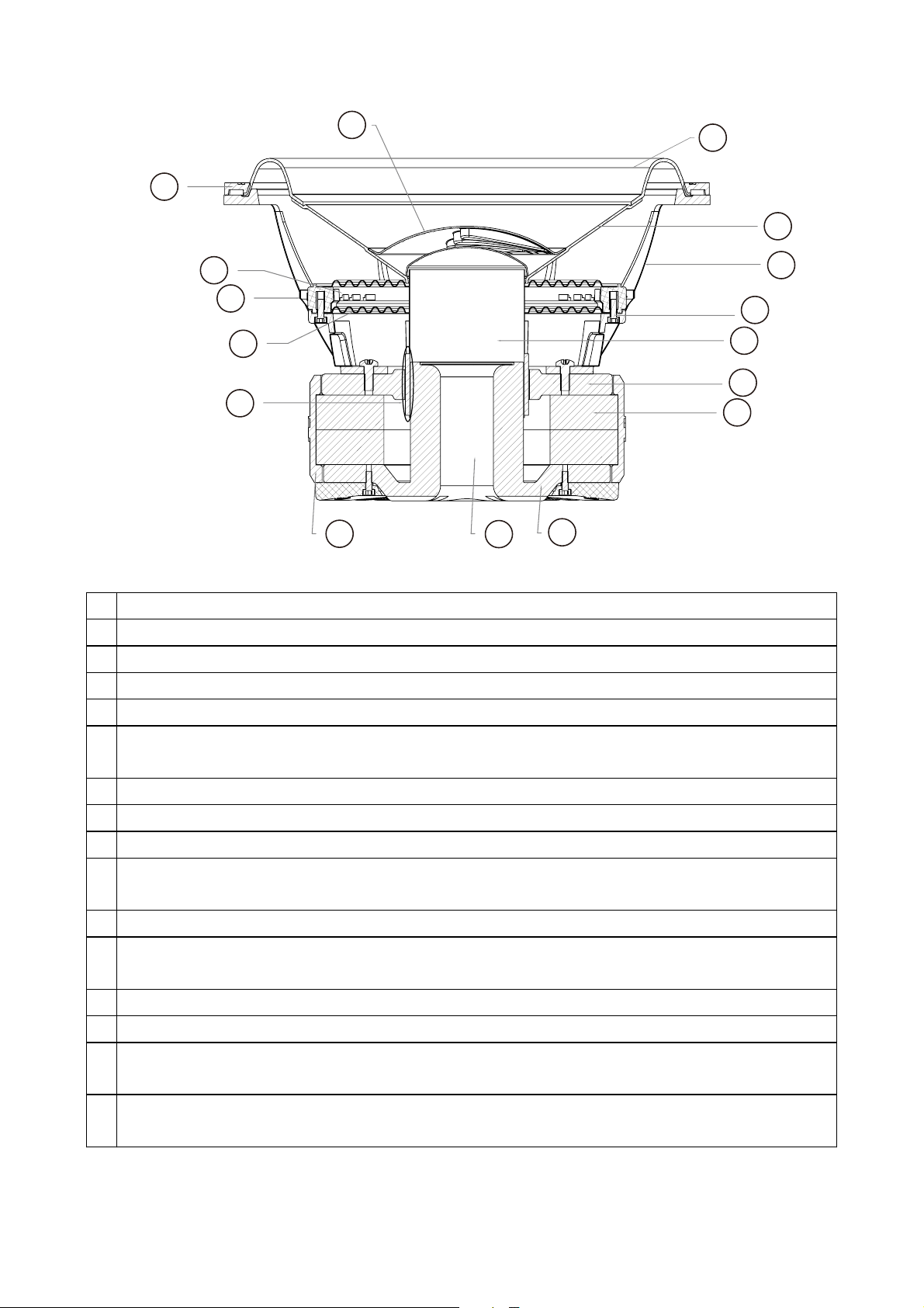
1 Polypropylene dust cap - moisture and UV resistant.
2 Oversized Santoprene surround for linear controlled long excursion.
3 Vented paper cone - moisture and UV resistant.
4 Custom stamped aluminum frame.
5 Spider ring attachment screws.Part of re-cone feature (8 hex screws)
6 Vented Kapton voice coil former (10” uses 2.5" voice coil former, 12” & 15" use a 3"
voice coil former).
7 20mm H type steel front plate
8 Large 2 stack ceramic magnets (15” use large 3 stack ceramic magnets).
9 12mm steel back plate/pole piece T yoke assembly.
10 1.2"(10” speaker) & 1.4”(12” & 15" speaker) vent. Part of the enhanced voice coil
cooling system (forced convection).
11 PVC magnet protector.
12 High temperature Aluminum voice coil wound.Dual 2 and 4 ohm voice coils
available.
13 Dual Interlaced Conex spider with stitched and looped tinsel leads attached.
14 Custom allen head screw terminals.A pair on each side(one pair for each voice coil).
15 Spider space and spider mounting ring assembly part of field re-cone kit attachment
method.(eight allen head screws).
16 Surround clamp ring,part of fiele re-cone kit attachment method.(10” & 12” use
eight allen head screws, 15” use twelve allen head screws).
© 2012 MD Audio Engineering²all rights reserved
3
__
_
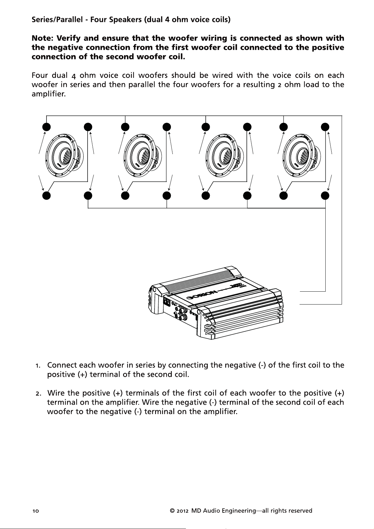
2 ohm
++
2 ohm
+
_
_
2 ohm
++
_
2 ohm
+
_
_
_
4 ohm
++
4 ohm
+
--
--
4 ohm
+
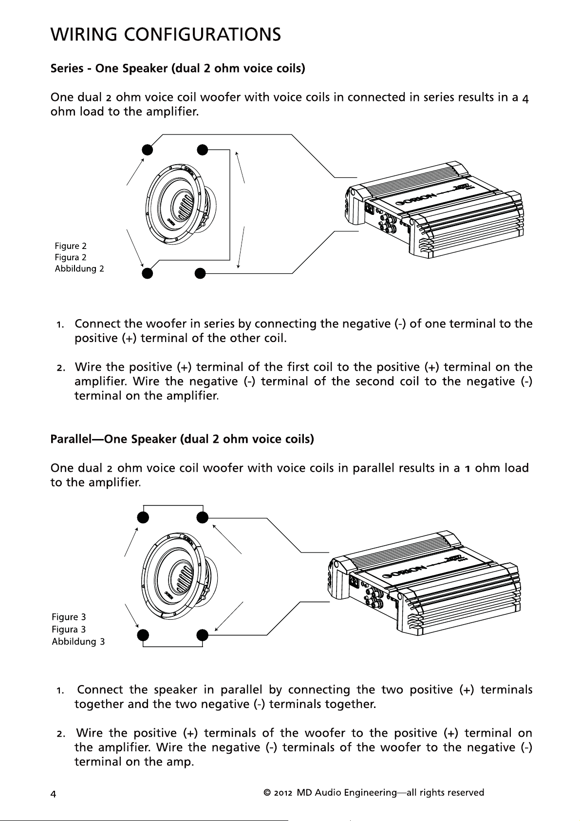
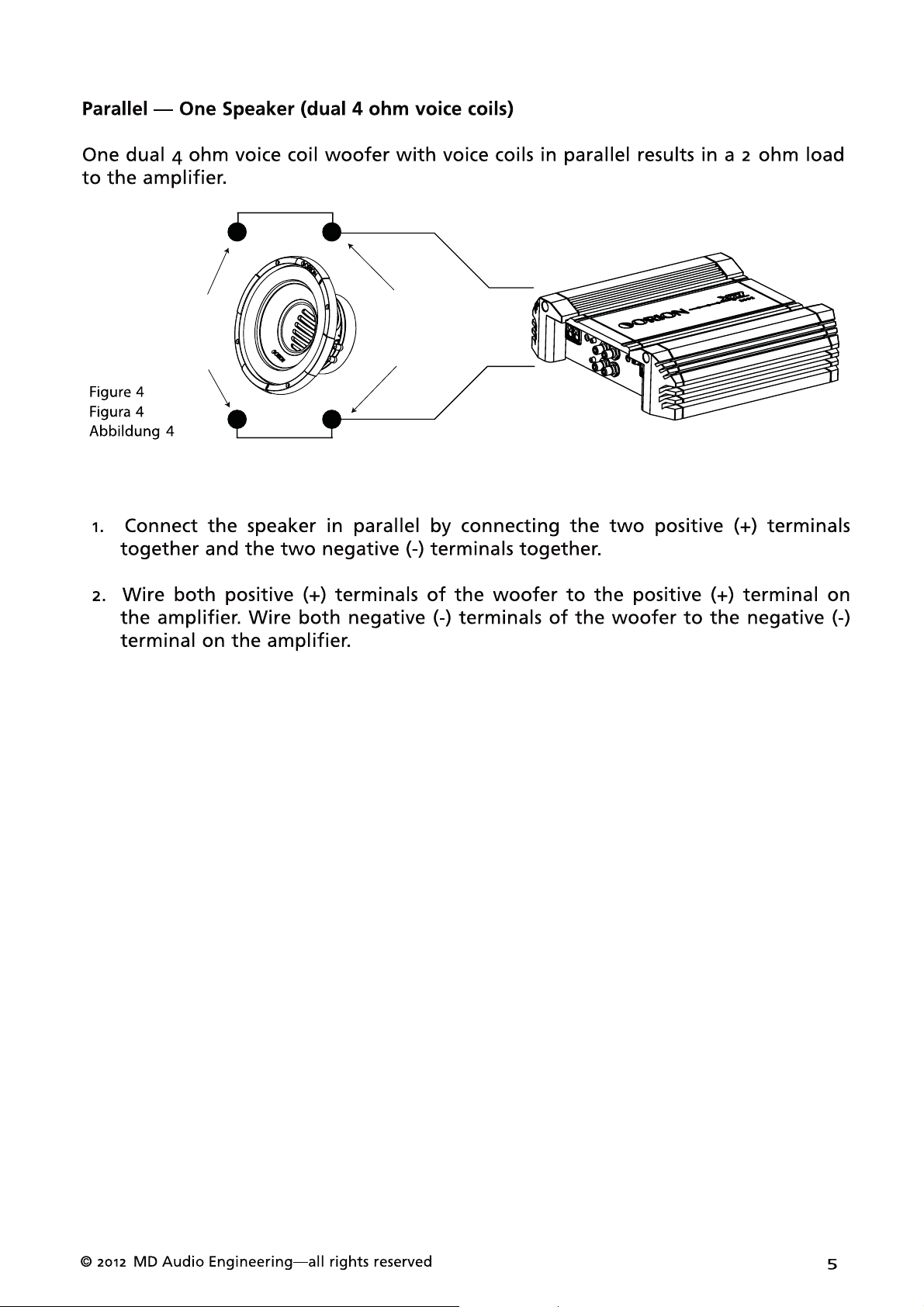
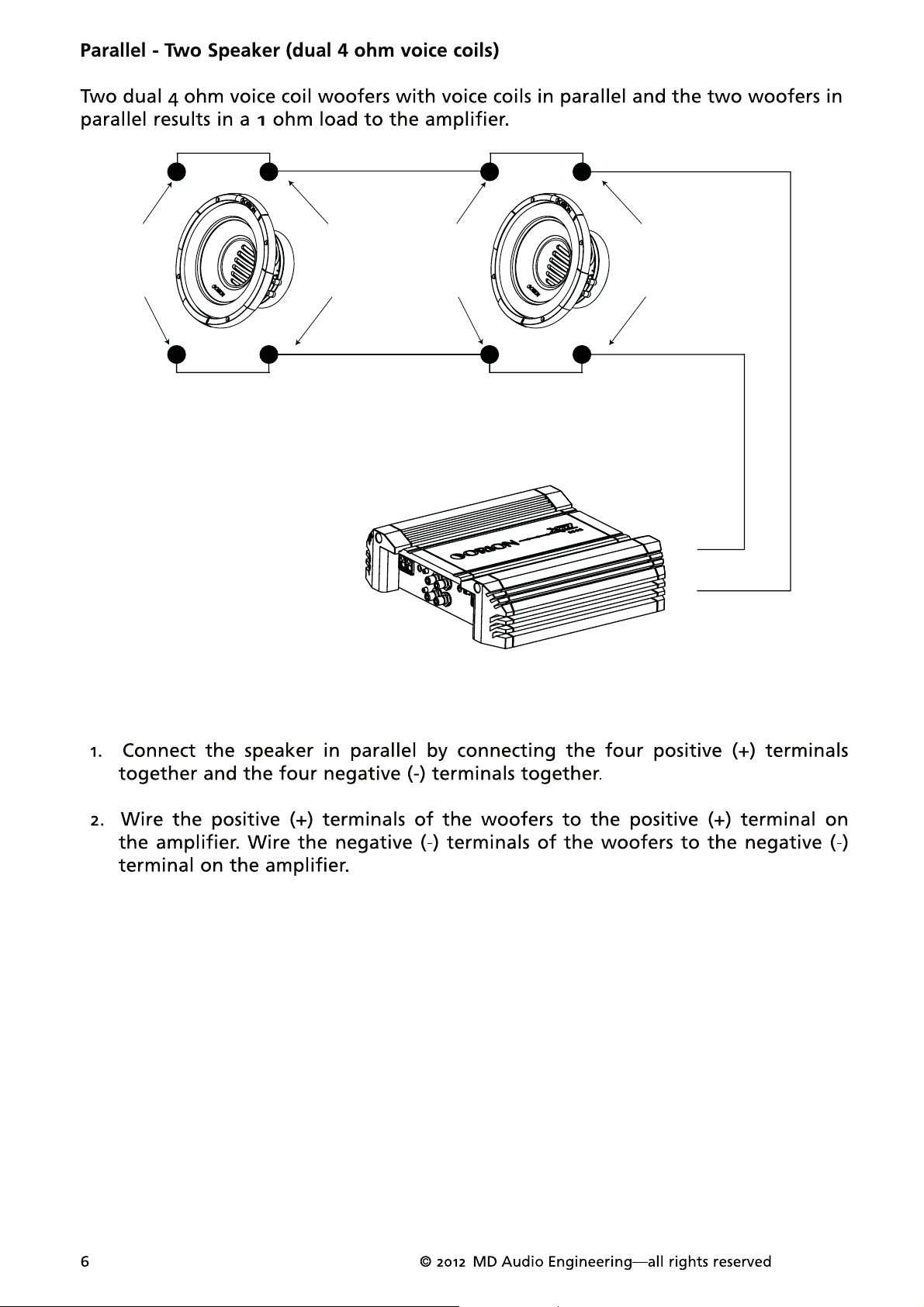
Figure 5
Figura 5
Abbildung 5
4 ohm
+
4 ohm
+
+
4 ohm
+
-
--
--
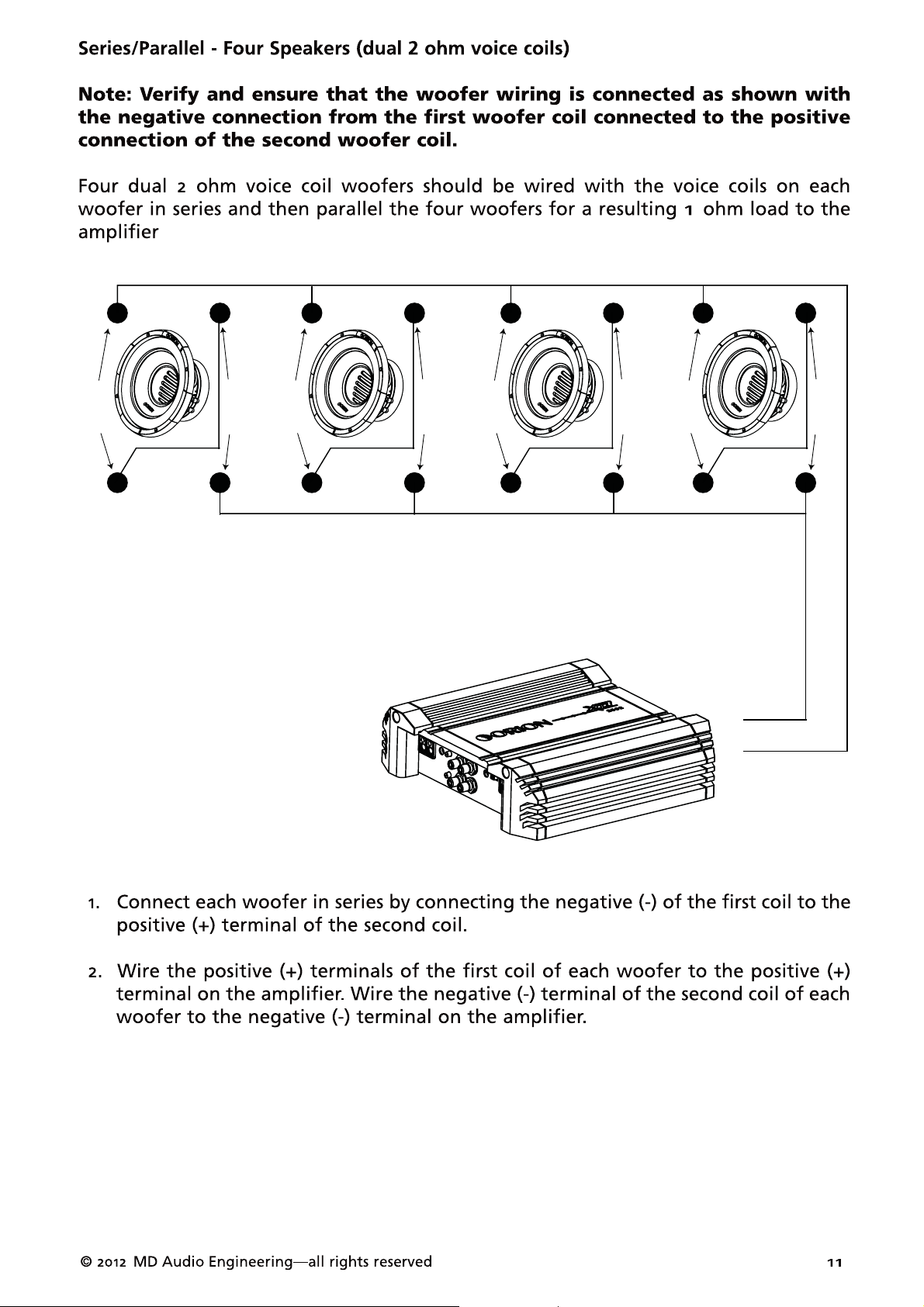
2 ohm
+
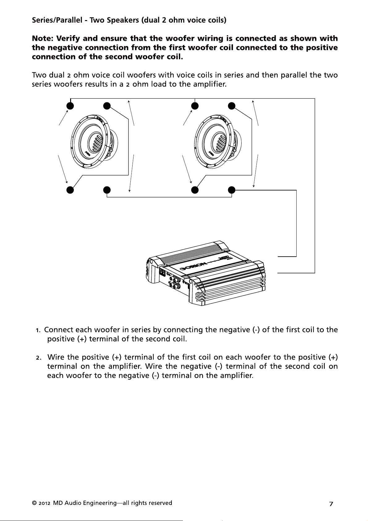
Figure 6
Figura 6
Abbildung 6
2 ohm
+
2 ohm
+
+
2 ohm
+
-
--
--
--
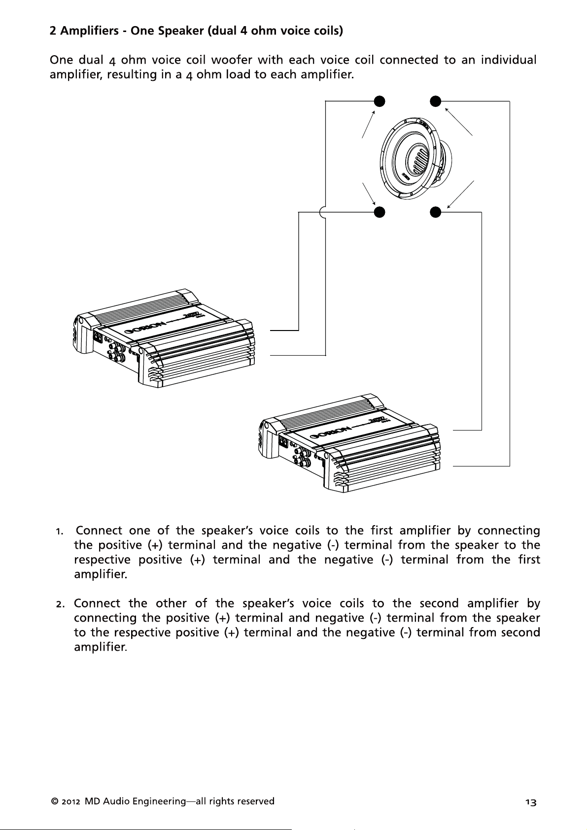
4 ohm
+
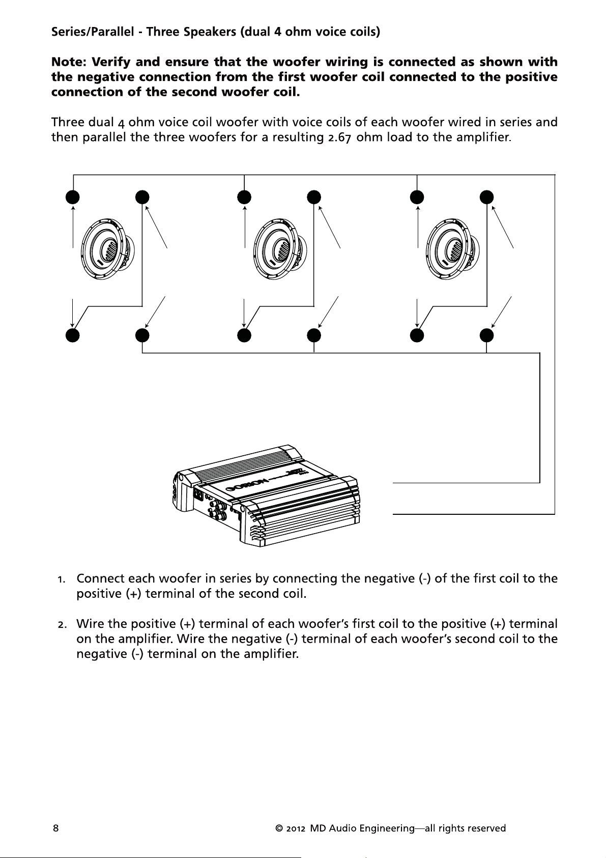
Figure 7
Figura 7
Abbildung 7
+
4 ohm
+
4 ohm
+
4 ohm
+
-
+
4 ohm
4 ohm
+
--
--
--
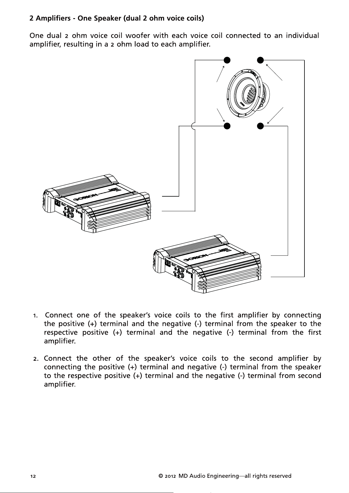
2 ohm
+
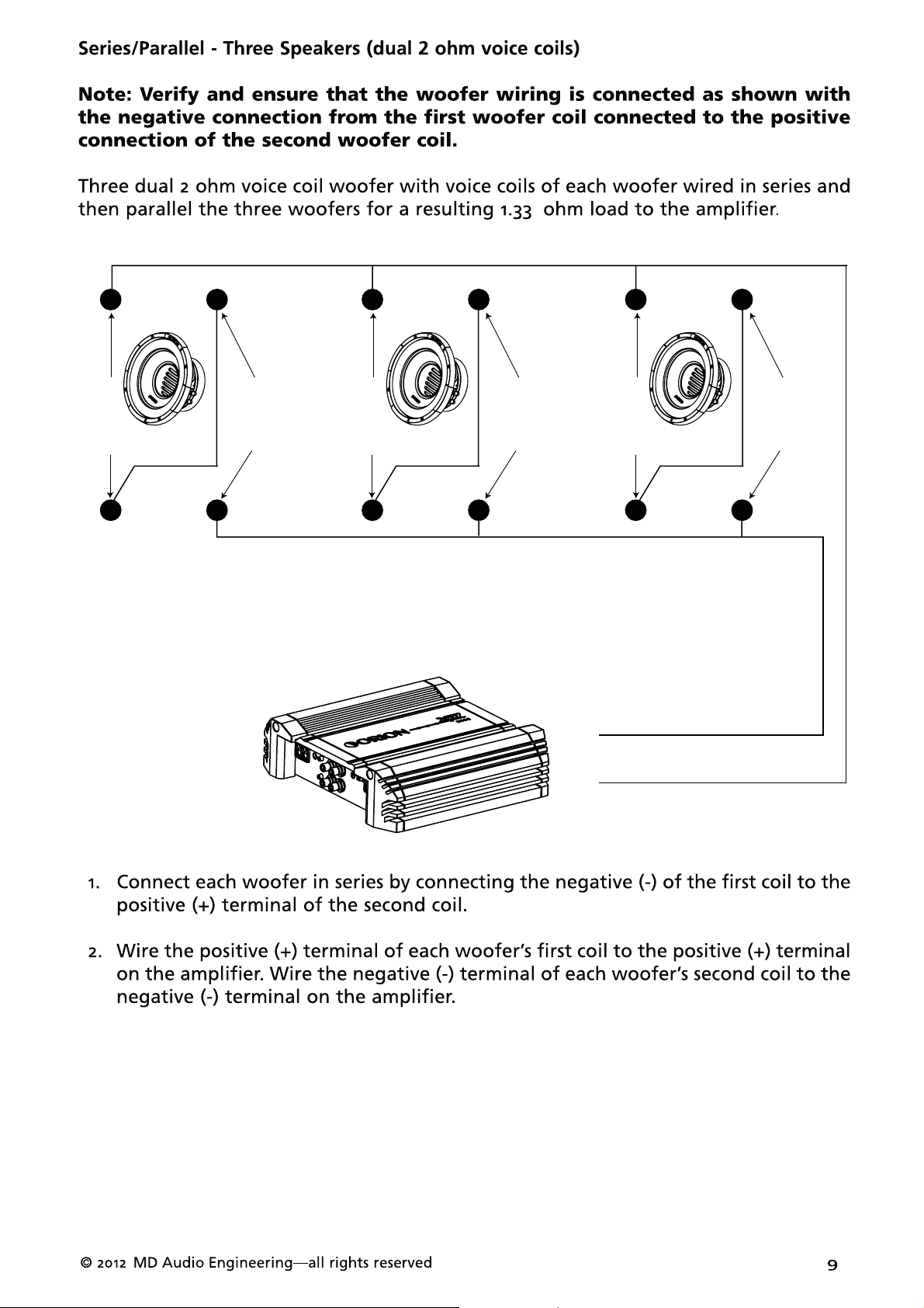
Figure 8
Figura 8
Abbildung 8
+
2 ohm
+
2 ohm
+
2 ohm
+
-
+
2 ohm
2 ohm
+
--
--
--
--
+
4 ohm
4 ohm
+
Figure 9
Figura 9
Abbildung 9
+
4 ohm
+
4 ohm
+
4 ohm
+
4 ohm
+
4 ohm
4 ohm
+
+
-
--
--
--
--
+
2 ohm
2 ohm
+
Figure 10
Figura 10
Abbildung 10
+
2 ohm
+
2 ohm
+
2 ohm
+
2 ohm
+
2 ohm
2 ohm
+
+
-
--
Figure 11
Figura 11
Abbildung 11
2 ohm
2 ohm
++
+
-
+
-
--
Figure 12
Figura 12
Abbildung 12
4 ohm
4 ohm
++
+
-
+
-

SPECIFICATIONS
Model/Part Number
Thiele/Small Parameters
Fs (free-air resonance, Hz)
Vas (equivalent compliance, cu. ft.)
Vas (equivalent compliance, liters)
Qms (Q, mechanical)
Qes (Q, electrical)
Qts (total driver Q)
Re (DC resistance, ohms)
Z (nominal impedance, ohms)
Le (inductance, mh)
Efficiency (1W @ 1M, dB)
Efficiency (2.86V @ 1M, dB)
Xmax (one way linear excursion, in.)
Xmax (one way linear excursion, mm)
RMS Power Watts
XTRPRO102D
39.3
0.634
17.952
9.776
0.407
0.391
3.4
4
2.293
87.8
90.8
0.472
12
900
XTRPRO104D
38.7
0.779
22.056
9.6
0.382
0.368
6.8
8
3.797
88.7
88.7
0.472
12
900
XTRPRO122D
37.1
1.033
29.255
11.349
0.5
0.479
3.4
4
2.392
88.6
91.6
0.528
13.4
1250
Nominal Power Watts
MAX Music Power Watts*
Mms (total moving mass, grams)
Cms (mechanical compliance, mm/N)
Bl (motor strength, Tesla-M)
Sd (effective radiating area, sq. cm.)
Sd (effective radiating area, sq. in.)
Frequency range (Hz)
Energy Bandwidth Product (EBP)**
Driver Physical Dimension
Speaker Displacement (cu ft)
Mounting hole diameter (inches/mm) 11.34 / 288 11.34 / 288 13.35 / 339
Mounting depth (inches/mm) 7.27 / 185 7.27 / 185 7.70 / 196
Magnet Weight (Oz)
Basket diameter (inches/mm)
Recommended Enclosures
3600
173.461
0.094
19.479
366.44
56.798
35 - 1kHz
97
0.1204
133
3600
145.959
0.116
25.886
366.44
56.798
35 - 1kHz
101
0.1204
133
250018001800
5000
258.594
0.071
20.875
539.13
83.565
32 - 1kHz
74
0.1674
176
Typical sealed enclosure (cu. ft.)
Vented enclosure (cu. ft.)***
Port tuning frequency (Hz)
Port diameter (inside,inches)
Port square equivalent (inches)
Port length (inches)
0.75
0.75
44
3
2.659x2.659
11.19
Specifications are subject to change without notice
14
© 2012 MD Audio Engineering²all rights reserved
0.75
0.75
44
3
2.659x2.659
11.19
1.5
1.5
40
4
3.545x3.545
11.26

SPECIFICATIONS
Model/Part Number
Thiele/Small Parameters
Fs (free-air resonance, Hz)
Vas (equivalent compliance, cu. ft.)
Vas (equivalent compliance, liters)
Qms (Q, mechanical)
Qes (Q, electrical)
Qts (total driver Q)
Re (DC resistance, ohms)
Z (nominal impedance, ohms)
Le (inductance, mh)
Efficiency (1W @ 1M, dB)
Efficiency (2.86V @ 1M, dB)
Xmax (one way linear excursion, in.)
Xmax (one way linear excursion, mm)
RMS Power Watts
XTRPRO124D
34.9 29.1 31.6
1.346
38.123 92.002 73.308
11.337
0.433 0.399 0.471
0.417
6.8 3.4 6.8
8
3.723 2.449 3.752
89.3
89.3 93.9 90.5
0.528
13.4 13.4 13.4
1250
XTRPRO152D XTRPRO154D
3.249 2.589
11.35 9.271
0.385 0.448
48
90.9 90.5
0.528 0.528
1800 1800
Nominal Power Watts
MAX Music Power Watts*
Mms (total moving mass, grams)
Cms (mechanical compliance, mm/N)
Bl (motor strength, Tesla-M)
Sd (effective radiating area, sq. cm.)
Sd (effective radiating area, sq. in.)
Frequency range (Hz)
Energy Bandwidth Product (EBP)**
Driver Physical Dimension
Speaker Displacement (cu ft)
Mounting hole diameter (inches/mm) 13.35 / 339 16.61 / 422 16.61 / 422
Mounting depth (inches/mm) 7.70 / 196 9.59 / 244 9.59 / 244
Magnet Weight (Oz)
Basket diameter (inches/mm)
Recommended Enclosures
2500 3600 3600
5000 7200 7200
223.823
0.093 0.085 0.067
28.453
539.13 876.16 876.16
83.565
32 - 1kHz 28 - 1kHz 28 - 1kHz
81
352.038 375.719
24.56 33.512
135.805 135.805
73 67
0.2703
373 373176
3072.04761.0
Typical sealed enclosure (cu. ft.)
Vented enclosure (cu. ft.)***
Port tuning frequency (Hz)
Port diameter (inside,inches)
Port square equivalent (inches)
Port length (inches)
1.5 2 2
1.5
40 36 36
4
3.545x3.545 3.545x3.545 3.545x3.545
11.26
Specifications are subject to change without notice
© 2012 MD Audio Engineering²all rights reserved
33
44
5.42 5.42
15

Explanation of Enclosure Specifications
There are many different factors that help determine the best style of enclosure for
you or your vehicle. Listed below are some factors that should be considered.
The size of the enclosure is directly proportional to the efficiency and power handling
of that speaker. A woofer in a smaller enclosure will handle more power than the
same woofer in a larger enclosure. The exact opposite is true for efficiency, a larger
enclosure will play lower frequencies at a louder volume with less power than a
smaller enclosure.
The following will explain differences in sealed enclosures. A large enclosure is
best suited if you have smaller amounts of power (25% to 50% of speaker’s power
handling), have a larger vehicle or looking for greater output. While the smaller
enclosure should be utilized if you have recommended power (50% to 100% of
speaker’s rated power handling), have a smaller (high gain) vehicle or are looking for
more accurate sound reproduction. A smaller sealed enclosure will yield more control,
this audible translates into faster and more accurate bass.
A vented enclosure will offer greater efficiency and stronger low bass output compared
to a sealed design. A vented enclosure uses the back wave (sound from the back side
of the cone) to reinforce the output from the speaker. A properly tuned enclosure will
yield gain across the entire bandwidth of the subwoofer system and offer more cone
control than a sealed enclosure. A low tuning will yield less overall gain but greater
extension (low bass). A high tuned enclosure will offer more gain but limit the low
end response of the system. One of the advantages of having a vented enclosure is
because it is tunable to a specific frequency and that tuning frequency is known as the
“Fb”. Another important box specification is “F3”, which is the roll-off frequency at
which the driver's response is down -3dB. This is an important number when it comes
to setting your high-pass filter or your ORION Intelli-Q. The Intelli-Q should be set at
the same frequency as the “F3”as this will keep the speaker from damaging or what
is know as over-loading.
Good planning and proper construction will assure the best response from your
system. The next pages will outline many different enclosures and designs that allow
the XTRPRO subwoofers to perform best. As always, if you have any questions on
enclosure construction or design, call Technical Support 1-800-753-0800.
© 2012 MD Audio Engineering—all rights reserved
17
© 2012 MD Audio Engineering—all rights reserved
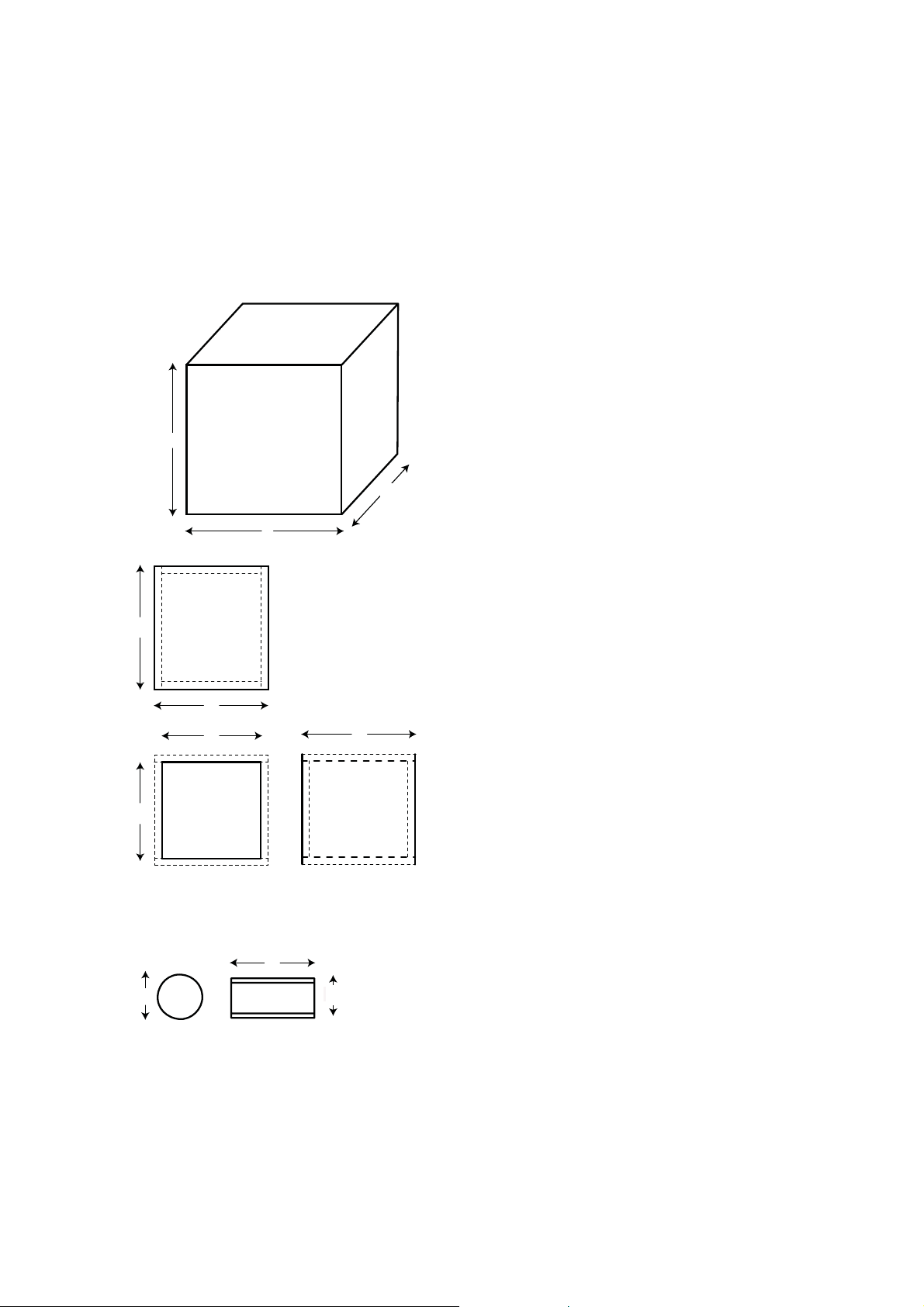
ENCLOSURE RECOMMENDATIONS
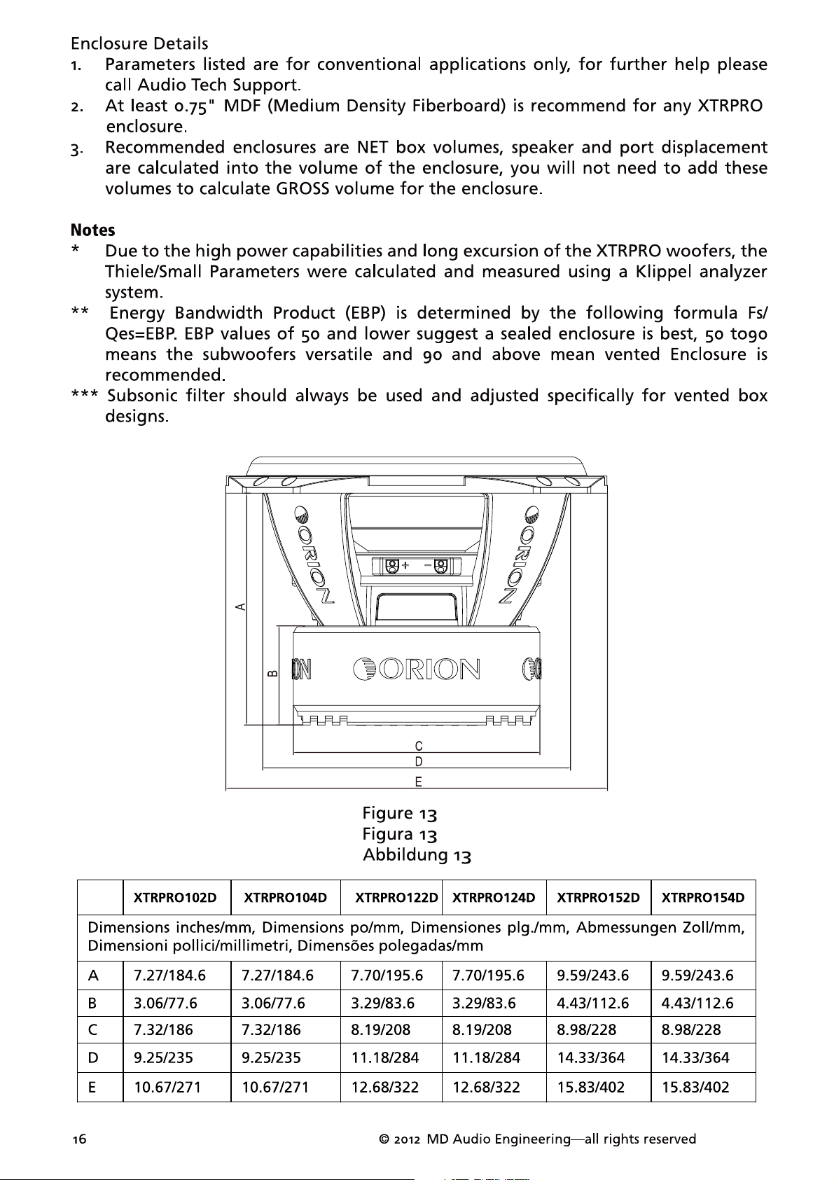
Enclosure Details
1. External dimensions calculated for 3/4” building material
2. Includes speaker displacement
3. Volumes given are net tuning volume
4. Enclosures include a minimal amount of damping material. Just enough material to
line the inside of the enclosure is required.
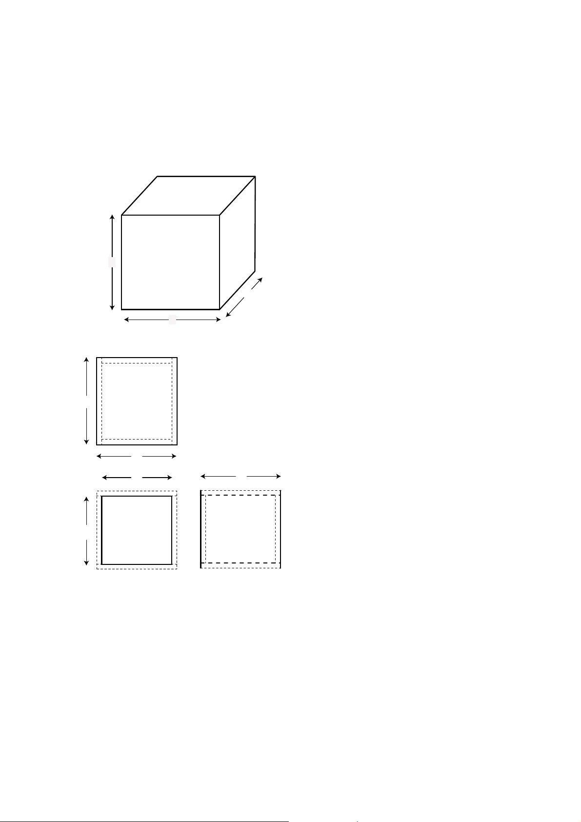
XTRPRO102 & 104 Sealed Enclosure Recommendations
Box
Properties
— Description
Type:
Closed
Shape: Prism,
—
Box
Square
— Box Parameters
Vb = 0.75
V(total) = 0.791
Qtc =
QL =
F3 = 50.61
Fill =
—
cu.ft
cu.ft
0.598
7
Hz
none
External
Internal
A
C
B Side = 0.75 in. (19
To p
c
a
&
Bottom
b
d
Front
Back
c
&
Sides
Wall
—Box
Box Shape: Square
1Top,1
1 Front, 1
2 Sides: height (a) = 10.5 in. (267
Dimensions
A = 12 in. (305
B = 15.5 in. (394
C = 10.8 in. (274
Dimensions
A = 10.5 in. (267
B = 14 in. (356
C = 9.3 in. (236
Thickness
Front = 0.75 in. (19
Par ts—
Bottom:
depth (c) = 10.8 in. (274
width (b) = 15.5 in. (394
thickness = 0.75 in. (19
Back:
height (a) = 10.5 in. (267
width (d) = 14 in. (356
thickness = 0.75 in. (19
depth (c) = 10.8 in. (274
thickness = 0.75 in. (19
mm)
mm)
mm)
Prism
mm)
mm)
mm)
mm)
mm)
mm)
mm)
mm)
mm)
mm)
mm)
mm)
mm)
mm)
Figure
14
Figura
14
Abbildung
18
14
—Driver
Mounting:
Mounting—
Front
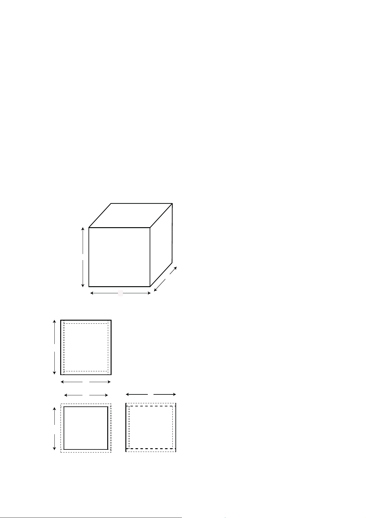
XTRPRO102 & 104 Vented Enclosure Recommendations
Box
Properties
— Description
Vented
Ty pe :
Shape: Prism,
—
Box
Square
— Box Parameters
Vb = 0.75
V(total) = 0.841
Fb = 44
QL =
F3 = 35.24
Fill =
Hz
7
none
—
cu.ft
cu.ft
Hz
— Vents
No. of Vents =
Vent shape =
Vent ends = one
Dv = 3 in. (76
Lv = 11.19 in. (284
—
1
round
flush
mm)
mm)
Figure
Figura
Abbildung
15
15
c
15
A
To p
Bottom
External
Internal
Wall
C
B
—Box
Box Shape: Square
&
b
d
c
1Top,1
1 Front, 1
Dimensions
A = 12 in. (305
B = 15.5 in. (394
C = 11.39 in. (289
mm)
mm)
mm)
Dimensions
A = 10.5 in. (267
B = 14 in. (356
C = 9.89 in. (251
mm)
mm)
mm)
Thickness
Front = 0.75 in. (19
Side = 0.75 in. (19
mm)
Parts—
Prism
Bottom:
depth (c) = 11.39 in. (289
width (b) = 15.5 in. (394
thickness = 0.75 in. (19
Back:
height (a) = 10.5 in. (267
width (d) = 14 in. (356
mm)
thickness = 0.75 in. (19
mm)
mm)
mm)
mm)
mm)
mm)
Front
&
a
Back
Sides
h
e
© 2012 MD Audio Engineering—all rights reserved
g
height (a) = 10.5 in. (267
depth (c) = 11.39 in. (289
thickness = 0.75 in. (19
—Driver
Vent
1
Duct:
Mounting—
Mounting:
Parts
Front
mm)
mm)
mm)
outside diameter (e) = 3.25 in. (83
inside diameter (g) = 3 in. (76
length (h) = 11.19 in. (284
mm)
mm)
mm)
19
© 2012 MD Audio Engineering—all rights reserved
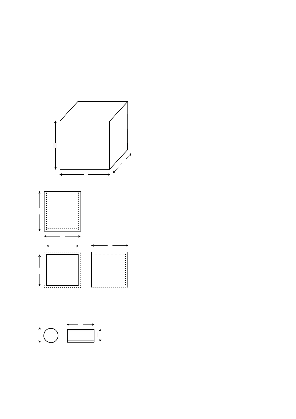
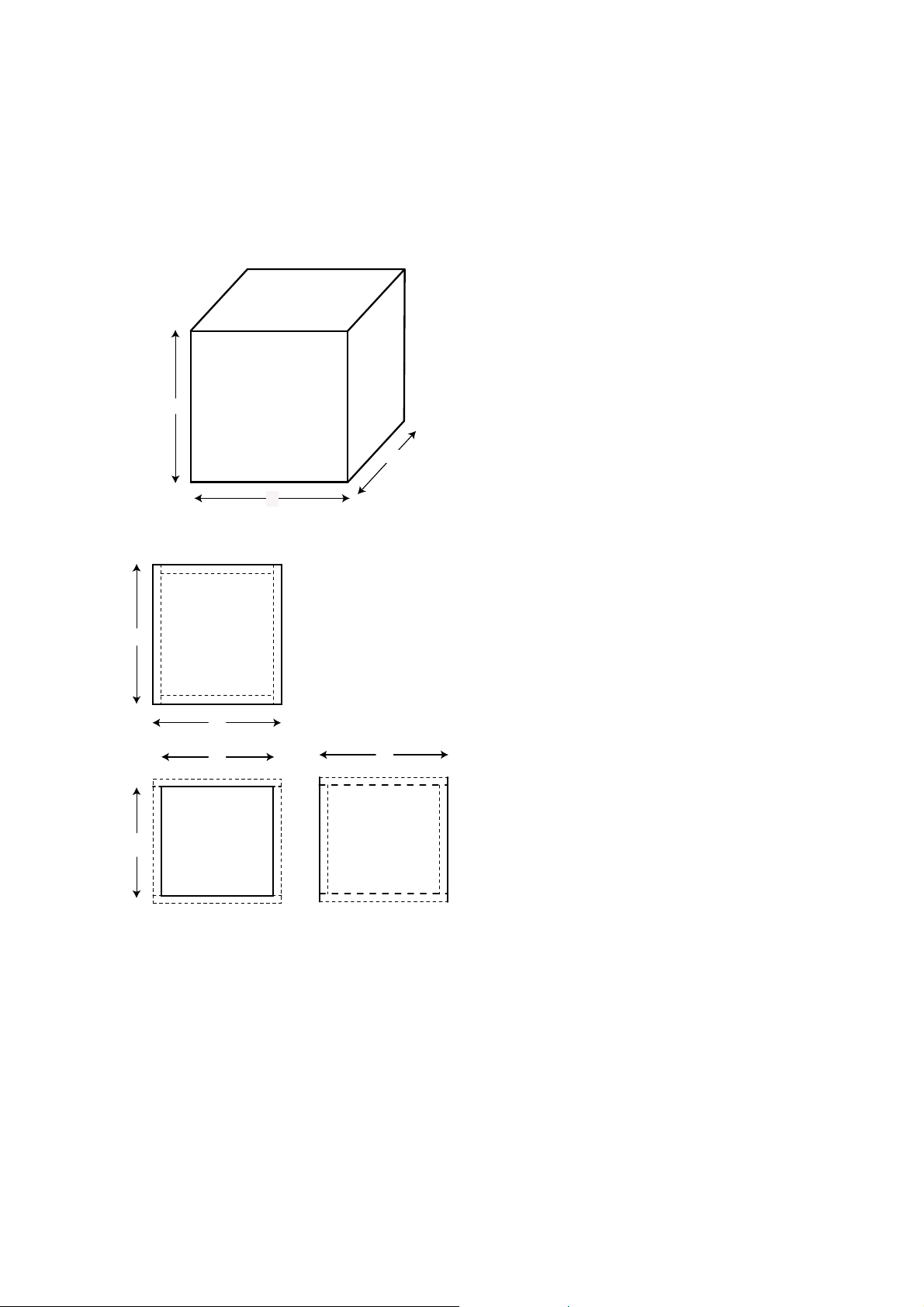
XTRPRO122 & 124 Sealed Enclosure Recommendations
Box
Properties
— Description
Closed
Ty p e:
Shape: Prism,
—
Box
Square
— Box Parameters
Vb = 1.5
V(total) = 1.55
Qtc =
QL =
F3 = 43.09
Fill =
—
cu.ft
cu.ft
0.717
6.886
Hz
none
External
Internal
A
Wall
C
B Side = 0.75 in. (19
To p
c
&
Bottom
b
d
Front
&
a
Back
c
Sides
Dimensions
A = 16 in. (406
B = 16 in. (406
C = 14.24 in. (362
Dimensions
A = 14.5 in. (368
B = 14.5 in. (368
C = 12.74 in. (324
Thickness
Front = 0.75 in. (19
—Box
Par ts—
Box Shape: Square
1Top, 1
Bottom:
depth (c) = 14.24 in. (362
width (b) = 16 in. (406
thickness = 0.75 in. (19
1 Front, 1
Back:
height (a) = 14.5 in. (368
width (d) = 14.5. (368
thickness = 0.75 in. (19
2
Sides:
height (a) = 14.5 in. (368
depth (c) = 14.24 in. (362
thickness = 0.75 in. (19
mm)
mm)
mm)
mm)
mm)
mm)
mm)
mm)
Prism
mm)
mm)
mm)
mm)
mm)
mm)
mm)
mm)
mm)
Figure
16
16
Figura
Abbildung
20
16
—Driver
Mounting:
Mounting—
Front
XTRPRO122 & 124 Vented Enclosure Recommendations
Box
Properties
— Description
Ty pe :
Vented
Shape: Prism,
—
Box
Square
— Box Parameters —Vb
=
V(total)
= 1.637
Fb = 40
QL =
F3 = 32.19
Fill =
1.5 cu.ft
cu.ft
Hz
6.886
Hz
none
— Vents
No. of Vents =
Vent shape =
Vent ends = one
Dv = 4 in. (102
Lv = 11.26 in. (286
—
1
round
flush
mm)
mm)
Figure
Figura
Abbildung
17
17
c
17
A
&
To p
Bottom
b
d
External
Internal
Wall
C
B
—Box
Box Shape: Square
1Top,1
1 Front, 1
c
Dimensions
A = 13.5 in. (343
B = 18.5 in. (470
mm)
mm)
C = 15.36 in. (390
Dimensions
A = 12 in. (305
B = 17 in. (432
mm)
mm)
C = 13.86 in. (352
Thickness
Front = 0.75 in. (19
Side = 0.75 in. (19
Parts—
Prism
Bottom:
depth (c) = 15.36 in. (390
width (b) = 18.5 in. (470
thickness = 0.75 in. (19
Back:
height (a) = 12 in. (305
width (d) = 17 in. (432
thickness = 0.75 in. (19
mm)
mm)
mm)
mm)
mm)
mm)
mm)
mm)
mm)
mm)
Front
&
a
Back
Sides
h
e
g
height (a) = 12 in. (305
depth (c) = 15.36 in. (390
thickness = 0.75 in. (19
—Driver
Vent
Duct:
1
Mounting—
Mounting:
Parts
Front
mm)
mm)
mm)
outside diameter (e) = 4.25 in. (108
inside diameter (g) = 4 in. (102
length (h) = 11.26 in. (286
mm)
mm)
mm)
© 2012 MD Audio Engineering—all rights reserved
21
© 2012 MD Audio Engineering—all rights reserved
XTRPRO152 & 154 Sealed Enclosure Recommendations
Box Properties
— Description —
— Box Parameters —Vb
Type: Closed Box
Shape: Prism, Square
V(total)
Qtc = 0.963
QL = 5.281
F3 = 37.55 Hz
Fill = none
External Dimensions
A = 17.5 in. (445 mm)
B = 17.5 in. (445 mm)
C = 15.52 in. (394 mm)
Internal Dimensions
A = 16 in. (406 mm)
A
B = 16 in. (406 mm)
C = 14.02 in. (356 mm)
C
Wall Thickness
Front = 0.75 in. (19 mm)
B
Side = 0.75 in. . (19 mm)
= 2 cu.ft
=
2.078 cu.ft
c
a
Figure
Figura
Abbildung
Top &
Bottom
b
d
Front
Back
18
18
18
—Box Parts—
Box Shape: Square Prism
1 Top, 1 Bottom:
depth (c) = 15.52 in. (394 mm)
width (b) = 17.5 in. (445 mm)
thickness = 0.75 in. (19 mm)
1 Front, 1 Back:
height (a) = 16 in. (406 mm)
c
width (d) = 16 in. (406 mm)
thickness = 0.75 in. (19 mm)
2 Sides:
&
Sides
height (a) = 16 in. (406 mm)
depth (c) = 15.52 in. (394 mm)
thickness = 0.75 in. (19 mm)
—Driver Mounting—
Mounting: Front
22
 Loading...