

Orion XTRPRO102, XTRPRO104, XTRPRO124, XTRPRO152, XTRPRO122 Owner's Manual
...
Subwoofer
MODEL
XTRPRO102
XTRPRO104
XTRPRO122
XTRPRO124
XTRPRO152
XTRPRO154
OWNER'S MANUAL


© 2012 MD Audio Engineering—all rights reserved
1
TABLE OF CONTENTS
English . . . . . . . . . . . . . . . . . . . . . . . . . . . . . . . . . . . . . . . . . . . . . . . . . . . . . . . . . . . . . . . 1
Français . . . . . . . . . . . . . . . . . . . . . . . . . . . . . . . . . . . . . . . . . . . . . . . . . . . . . . . . . . . . .
25
Español. . . . . . . . . . . . . . . . . . . . . . . . . . . . . . . . . . . . . . . . . . . . . . . . . . . . . . . . . . . . . . 35
Deutsch . . . . . . . . . . . . . . . . . . . . . . . . . . . . . . . . . . . . . . . . . . . . . . . . . . . . . . . . . . . . . 45
Italiano. . . . . . . . . . . . . . . . . . . . . . . . . . . . . . . . . . . . . . . . . . . . . . . . . . . . . . . . . . . . . . 55
Português . . . . . . . . . . . . . . . . . . . . . . . . . . . . . . . . . . . . . . . . . . . . . . . . . . . . . . . . . . . 65
Introduction . . . . . . . . . . . . . . . . . . . . . . . . . . . . . . . . . . . . . . . . . . . . . . . . . . . . . . . 1
Practice Safe Sound™ . . . . . . . . . . . . . . . . . . . . . . . . . . . . . . . . . . . . . . . . . . . . . . . . 1
What's in the box . . . . . . . . . . . . . . . . . . . . . . . . . . . . . . . . . . . . . . . . . . . . . . . . . . . .2
Tools of the Trade . . . . . . . . . . . . . . . . . . . . . . . . . . . . . . . . . . . . . . . . . . . . . . . . . . . 2
Installation . . . . . . . . . . . . . . . . . . . . . . . . . . . . . . . . . . . . . . . . . . . . . . . . . . . . . . . . . 2
Finding Speaker Mounting Locations . . . . . . . . . . . . . . . . .. . . . . . . . . . . . . . . . . . . . 2
Features . . . . . . . . . . . . . . . . . . . . . . . . . . . . . . . . . . . . . . . . . . . . . . . . . . . . . . . . . . 3
Wiring Configurations . . . . . . . . . . . . . . . . . . . . . . . . . . . . . . . . . . . . . . . . . . . . . . . . .4
Specifications . . . . . . . . . . . . . . . . . . . . . . . . . . . . . . . . . . . . . . . . . . . . . . . . . . . . . . 14
Enclosure Recommendations . . . . . . . . . . . . . . . . . . . . . . . . . . . . . . . . . . . . . . . . . . .18
Warranty . . . . . . . . . . . . . . . . . . . . . . . . . . . . . . . . . . . . . . . . . . . . . . . . . . Back cover
INTRODUCTION
Thank you for your purchase of the Orion XTRPRO Subwoofers. These woofers
represent a combination of incredible performance and value. We at Orion strive to
give you the latest up to date information about this product. What we can’t give
you with the manual is personal installation or technical experience. If you have
questions concerning the use or application of this product please refer to the nearest
Orion dealer for assistance, visit www.orioncaraudio.com, or call the technical support
hotline at
1-800-876-0800.
As we are always finding new ways to improve our product,
the features and specifications are subject to change without notice.
PRACTICE SAFE SOUND™
Continuous exposure to sound pressure levels over 100dB may cause permanent
hearing loss. High powered automotive sound systems can generate sound pressure
levels in excess of 130dB. When playing your system at high levels, please use hearing
protection and prevent long term exposure.
Model Number:
Serial Number:
Date of Purchase:

2
© 2012 MD Audio Engineering—all rights reserved
WHAT’S IN THE BOX
Included in this box are all the necessary mounting hardware and cables for your basic
installation. Listed below is a detailed list of the components included in this system
package.
Quantity Description
1
Owner's Manual
1
Orion XTRPRO woofer
1
Mounting template
1
Trim ring with hardware..
TOOLS OF THE TRADE
Listed are the majority of the tools required to perform the installation. Having the
proper tools will make the installation much easier. It is very difficult when you get
half way through the installation and discover that you require a specific tool to
get yourself through a particular part of the installation. Some of these tools are
necessities. Some make the job much easier.
• Marking Pen • Electric Drill and assorted Bits
• Phillips Screwdriver • Wire Strippers
• Allen Wrenches • Volt/Ohm Meter (Optional)
• Table Saw • Jig Saw
• Wire Cutters • Wire Crimpers
INSTALLATION
The performance of these XTRPRO subwoofers is directly proportional to the quality
of the installation. Care taken with the installation process will be rewarded by years
of satisfying performance. If you are unsure of your installation abilities, please
refer to your local authorized ORION dealer for assistance. Orion dealers are trained
professionals dedicated to extracting the maximum performance out of your Orion
system. If you decide to install this speaker system yourself, please read the entire
section on sealed and vented enclosures before starting the installation.
FINDING SPEAKER MOUNTING LOCATIONS
Choosing the correct speaker locations will have the greatest effect on the sound
quality of the system. Different considerations are needed when choosing the
locations that best suit your needs. The locations must be large enough for the
speakers to fit. Care is needed to ensure that the location you have chosen will not
affect any of the mechanical or electrical operations of the vehicle.
Determining the best location for the speakers will depend on your cosmetic needs
and your vehicle’s interior. Usually the woofers are installed in the trunk, rear seat, or
rear of the vehicle..
© 2012 MD Audio Engineering—all rights reserved
3
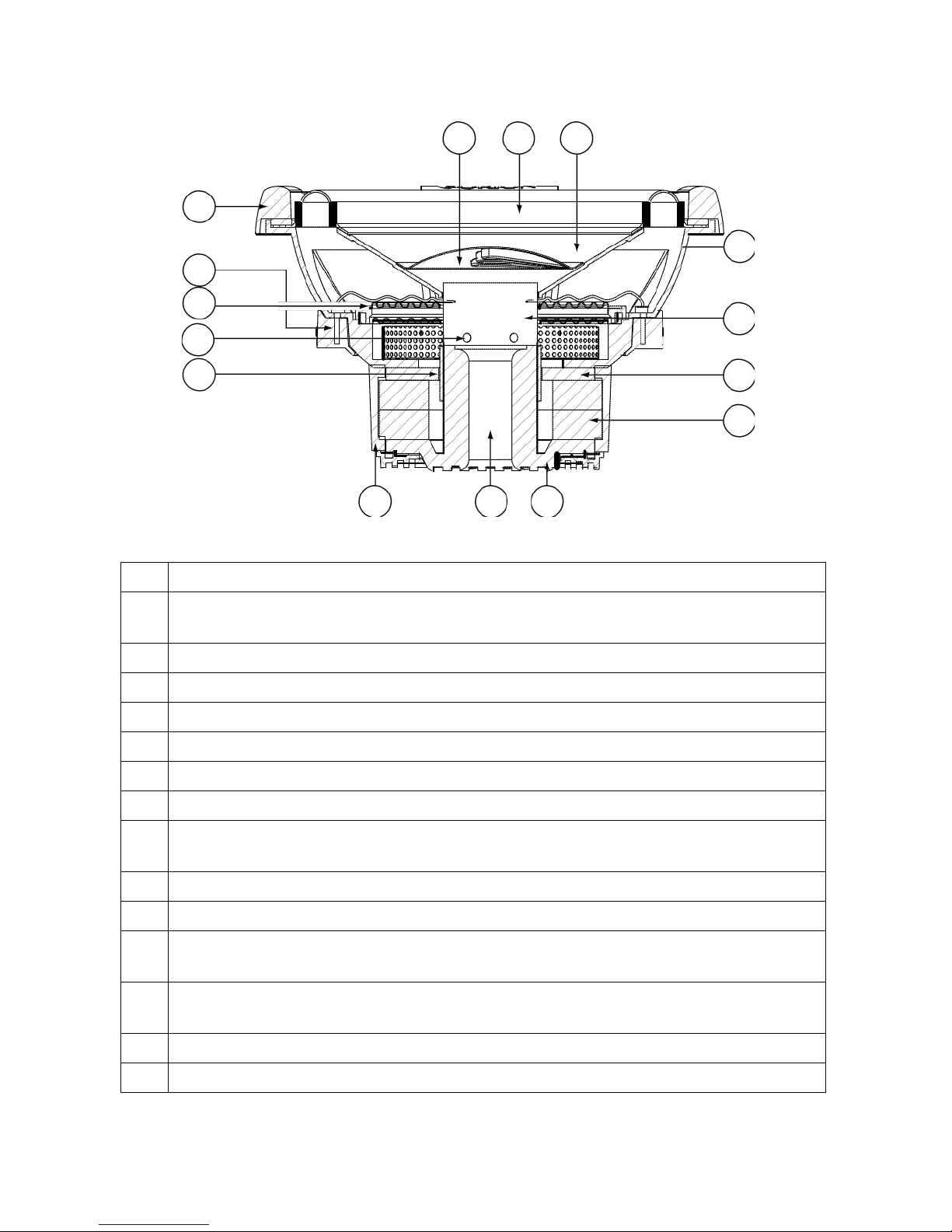
FEATURES
1 2
3
15
4
14
13
5
12
11
6
7
Figure
1
Figura
1
Abbildung
1
10 9
8
1
Polypropylene dust cap - moisture and UV resistant.
2
Oversized NBR (Nitrile-butadiene Rubber) surround for linear controlled
long excursion.
3
Paper cone - moisture and UV resistant.
4
Custom cast aluminum frame.
5
Vented Aluminum voice coil former (2.5" voice coil former).
6
8mm steel front plate.
7
Large 2 stack ceramic magnets.
8
8mm steel back plate/pole piece T yoke assembly.
9
1.125"
vent. Part of the enhanced voice coil cooling system (forced
convection).
10 PVC magnet protector.
11
High temperature Copper dual 2 ohm or dual 4 ohm voice coil.
12
Venting in voice coil former. Part of the enhanced voice coil cooling system
(forced convection).
1
3 Dual Interlaced Conex spider with stitched and looped tinsel leads
attached.
14 Custom terminal blocks.
15 ABS Trim Ring.
4
© 2012 MD Audio Engineering—all rights reserved
2 ohm
2 ohm
2 ohm
2 ohm
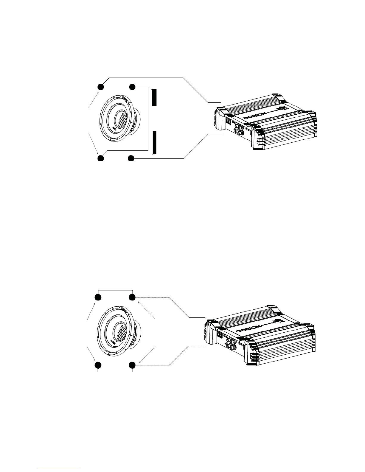
WIRING CONFIGURATIONS
Series - One Speaker (dual 2 ohm voice coils)
One dual 2 ohm voice coil woofer with voice coils in connected in series results in a 4
ohm load to the amplifier.
_ _
_
+
Figure
2
Figura
2
Abbildung 2
+ +
1. Connect the woofer in series by connecting the negative (-) of one terminal to the
positive (+) terminal of the other coil.
2. Wire the positive (+) terminal of the first coil to the positive (+) terminal on the
amplifier. Wire the negative (-) terminal of the second coil to the negative (-)
terminal on the amplifier.
Parallel—One Speaker (dual 2 ohm voice coils)
One dual 2 ohm voice coil woofer with voice coils in parallel results in a 1 ohm load
to the amplifier.
_
_
_
Figure 3
+
Figura 3
+ +
Abbildung
3
1. Connect the speaker in parallel by connecting the two positive (+) terminals
together and the two negative (-) terminals together.
2. Wire the positive (+) terminals of the woofer to the positive (+) terminal on
the amplifier. Wire the negative (-) terminals of the woofer to the negative (-)
terminal on the amp.
© 2012 MD Audio Engineering—all rights reserved
5
4 ohm
4 ohm
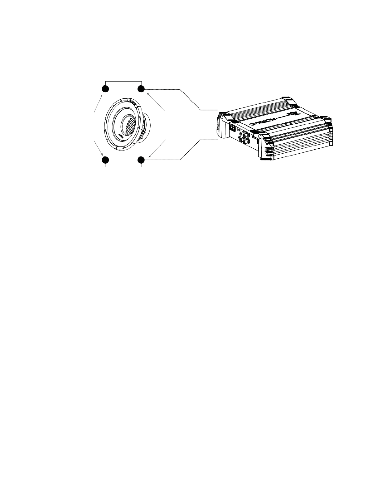
Parallel — One Speaker (dual 4 ohm voice coils)
One dual 4 ohm voice coil woofer with voice coils in parallel results in a 2 ohm load
to the amplifier.
_
_
_
Figure 4
+
Figura 4
+ +
Abbildung
4
1. Connect the speaker in parallel by connecting the two positive (+) terminals
together and the two negative (-) terminals together.
2. Wire both positive (+) terminals of the woofer to the positive (+) terminal on
the amplifier. Wire both negative (-) terminals of the woofer to the negative (-)
terminal on the amplifier.
6
© 2012 MD Audio Engineering—all rights reserved
4 ohm
4 ohm
4 ohm
4 ohm
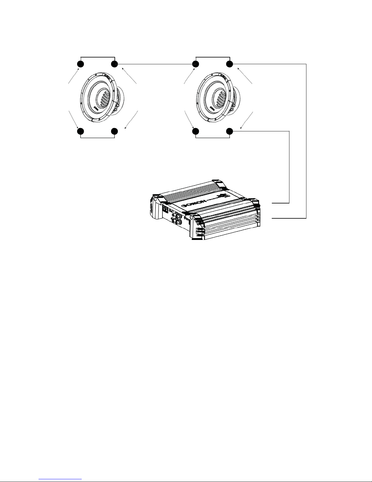
Parallel - Two Speaker (dual 4 ohm voice coils)
Two dual 4 ohm voice coil woofers with voice coils in parallel and the two woofers in
parallel results in a
1
ohm load to the amplifier.
- - - -
+
+
+
+
Figure 5
+
Figura 5
Abbildung 5
-
1. Connect the speaker in parallel by connecting the four positive (+) terminals
together and the four negative (-) terminals together.
2. Wire the positive (+) terminals of the woofers to the positive (+) terminal on
the amplifier. Wire the negative (-) terminals of the woofers to the negative (-)
terminal on the amplifier.
© 2012 MD Audio Engineering—all rights reserved
7
2 ohm
2 ohm
2 ohm
2 ohm
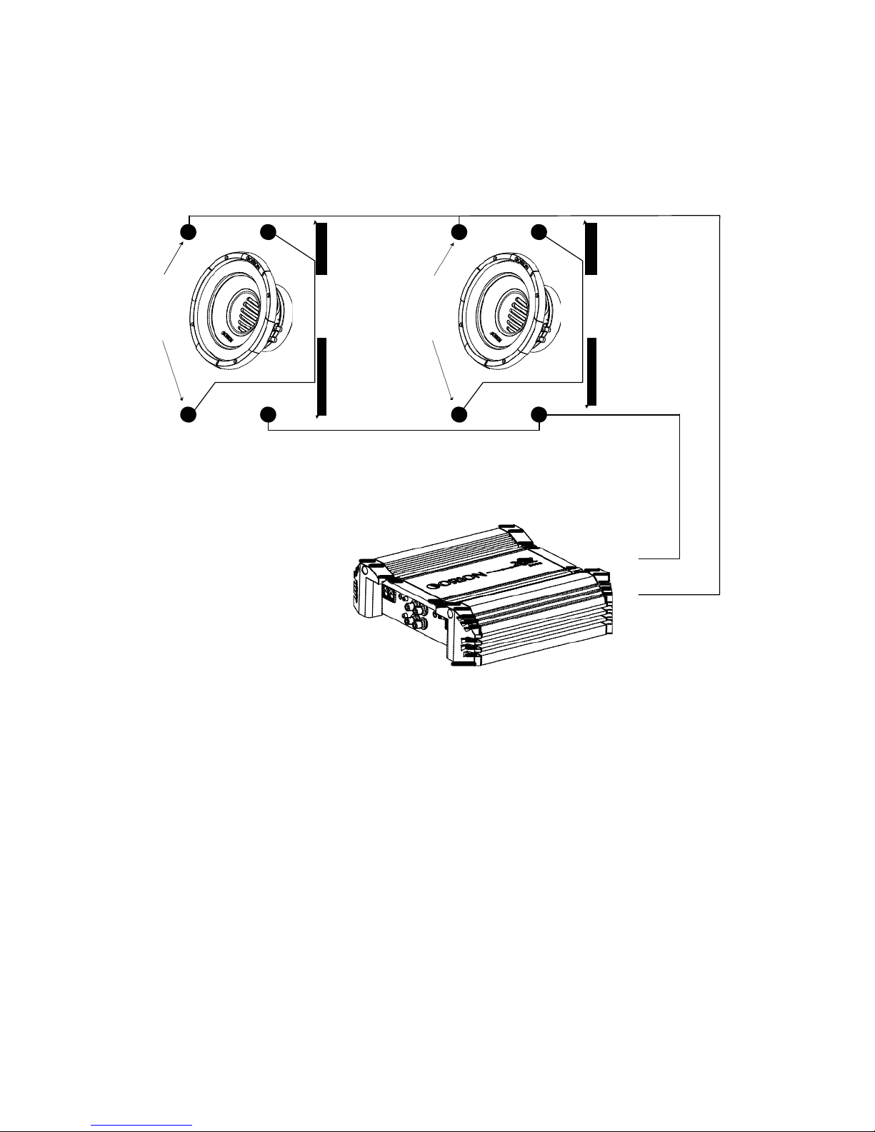
Series/Parallel - Two Speakers (dual 2 ohm voice coils)
Note: Verify and ensure that the woofer wiring is connected as shown with
the negative connection from the first woofer coil connected to the positive
connection of the second woofer coil.
Two dual 2 ohm voice coil woofers with voice coils in series and then parallel the two
series woofers results in a 2 ohm load to the amplifier.
- - - -
+
+
+
+
Figure 6
+
Figura 6
Abbildung 6
-
1. Connect each woofer in series by connecting the negative (-) of the first coil to the
positive (+) terminal of the second coil.
2. Wire the positive (+) terminal of the first coil on each woofer to the positive (+)
terminal on the amplifier. Wire the negative (-) terminal of the second coil on
each woofer to the negative (-) terminal on the amplifier.
8
© 2012 MD Audio Engineering—all rights reserved
4
ohm
4
ohm
4
ohm
4
ohm
4
ohm
4
ohm
Series/Parallel - Three Speakers (dual 4 ohm voice coils)
Note: Verify and ensure that the woofer wiring is connected as shown with
the negative connection from the first woofer coil connected to the positive
connection of the second woofer coil.
Three dual 4 ohm voice coil woofer with voice coils of each woofer wired in series and
then parallel the three woofers for a resulting 2.67 ohm load to the amplifier.
- - - - -
-
+
+
+
+
+
+
Figure 7
+
Figura
7
Abbildung 7
-
1. Connect each woofer in series by connecting the negative (-) of the first coil to the
positive (+) terminal of the second coil.
2. Wire the positive (+) terminal of each woofer’s first coil to the positive (+) terminal
on the amplifier. Wire the negative (-) terminal of each woofer’s second coil to the
negative (-) terminal on the amplifier.

© 2012 MD Audio Engineering—all rights reserved
9
2
ohm
2
ohm
2
ohm
2
ohm
2
ohm
2
ohm
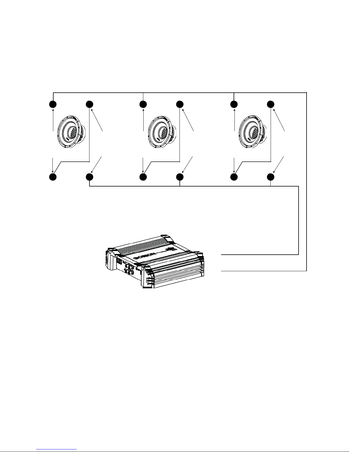
Series/Parallel - Three Speakers (dual 2 ohm voice coils)
Note: Verify and ensure that the woofer wiring is connected as shown with
the negative connection from the first woofer coil connected to the positive
connection of the second woofer coil.
Three dual 2 ohm voice coil woofer with voice coils of each woofer wired in series and
then parallel the three woofers for a resulting 1.33 ohm load to the amplifier.
- - - - -
-
+
+
+
+
+
+
Figure 8
+
Figura
8
Abbildung 8
-
1. Connect each woofer in series by connecting the negative (-) of the first coil to the
positive (+) terminal of the second coil.
2. Wire the positive (+) terminal of each woofer’s first coil to the positive (+) terminal
on the amplifier. Wire the negative (-) terminal of each woofer’s second coil to the
negative (-) terminal on the amplifier.
10
© 2012 MD Audio Engineering—all rights reserved
4
ohm
4
ohm
4
ohm
4
ohm
4
ohm
4
ohm
4
ohm
4
ohm
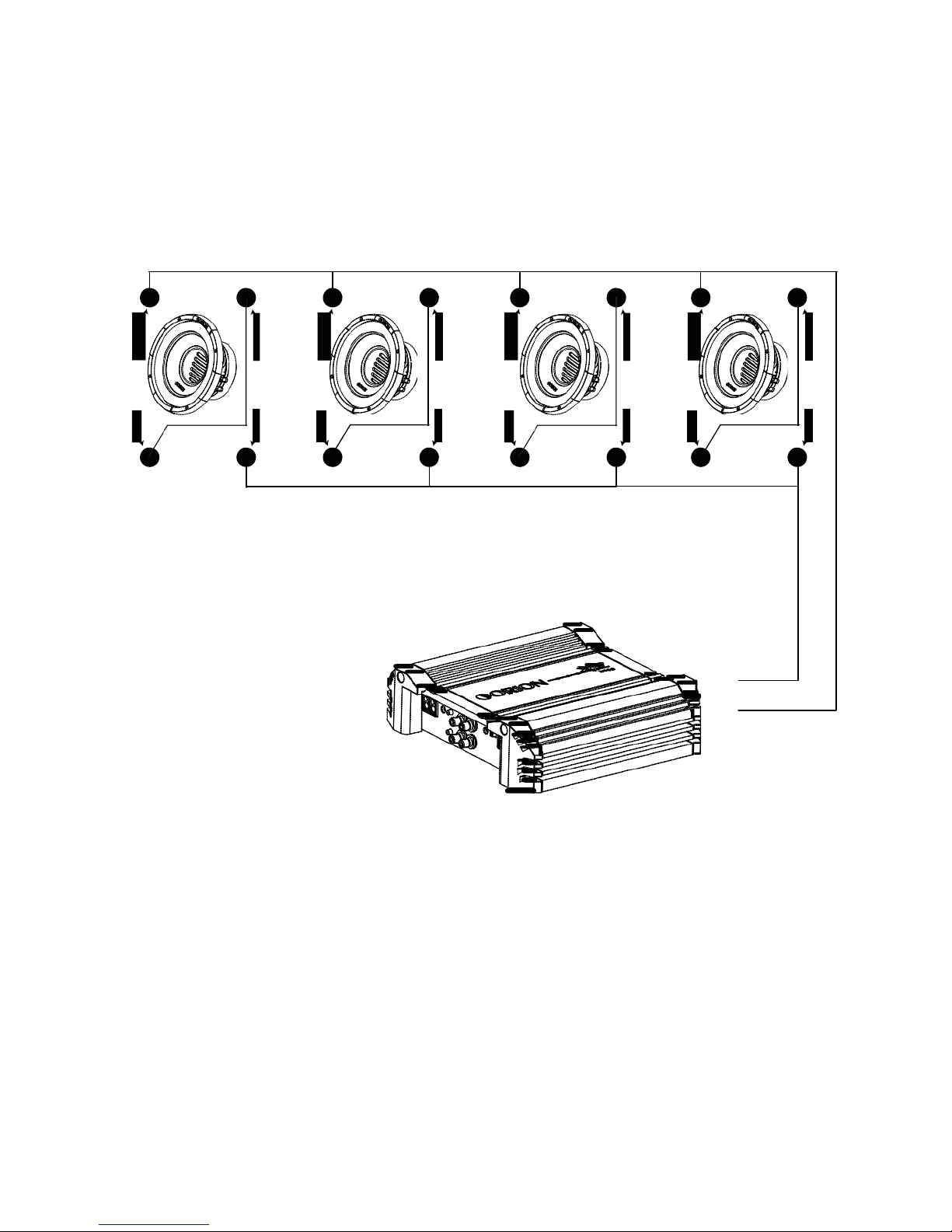
Series/Parallel - Four Speakers (dual 4 ohm voice coils)
Note: Verify and ensure that the woofer wiring is connected as shown with
the negative connection from the first woofer coil connected to the positive
connection of the second woofer coil.
Four dual 4 ohm voice coil woofers should be wired with the voice coils on each
woofer in series and then parallel the four woofers for a resulting 2 ohm load to the
amplifier.
- - - -
- - - -
+
+
+
+
+
+
+
+
Figure
9
Figura 9
+
Abbildung
9
-
1. Connect each woofer in series by connecting the negative (-) of the first coil to the
positive (+) terminal of the second coil.
2. Wire the positive (+) terminals of the first coil of each woofer to the positive (+)
terminal on the amplifier. Wire the negative (-) terminal of the second coil of each
woofer to the negative (-) terminal on the amplifier.

© 2012 MD Audio Engineering—all rights reserved
11
2
ohm
2
ohm
2
ohm
2
ohm
2
ohm
2
ohm
2
ohm
2
ohm
Series/Parallel - Four Speakers (dual 2 ohm voice coils)
Note: Verify and ensure that the woofer wiring is connected as shown with
the negative connection from the first woofer coil connected to the positive
connection of the second woofer coil.
Four dual 2 ohm voice coil woofers should be wired with the voice coils on each
woofer in series and then parallel the four woofers for a resulting
1
ohm load to the
amplifier
- - - -
- - - -
+
+
+
+
+
+
+
+
Figure
10
Figura 10
+
Abbildung
10
-
1. Connect each woofer in series by connecting the negative (-) of the first coil to the
positive (+) terminal of the second coil.
2. Wire the positive (+) terminals of the first coil of each woofer to the positive (+)
terminal on the amplifier. Wire the negative (-) terminal of the second coil of each
woofer to the negative (-) terminal on the amplifier.
12
© 2012 MD Audio Engineering—all rights reserved
2 ohm
2 ohm
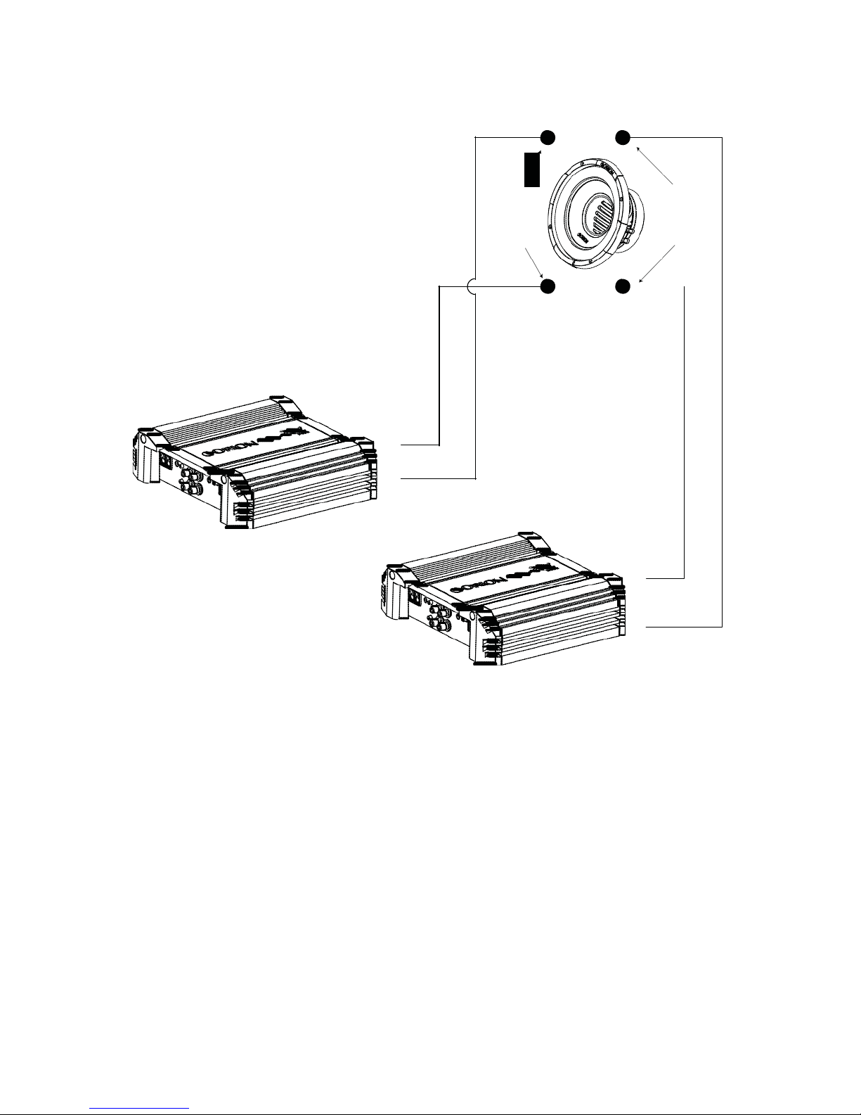
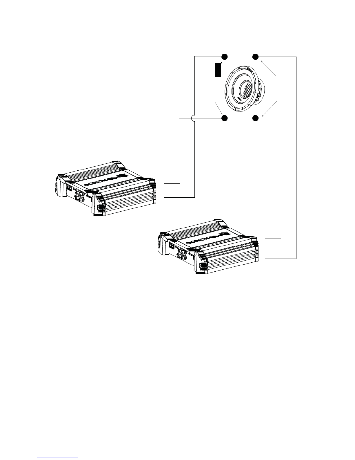
2 Amplifiers - One Speaker (dual 2 ohm voice coils)
One dual 2 ohm voice coil woofer with each voice coil connected to an individual
amplifier, resulting in a 2 ohm load to each amplifier.
- -
+ +
+
-
+
Figure 11
Figura
11
Abbildung 11
-
1. Connect one of the speaker’s voice coils to the first amplifier by connecting
the positive (+) terminal and the negative (-) terminal from the speaker to the
respective positive (+) terminal and the negative (-) terminal from the first
amplifier.
2. Connect the other of the speaker’s voice coils to the second amplifier by
connecting the positive (+) terminal and negative (-) terminal from the speaker
to the respective positive (+) terminal and the negative (-) terminal from second
amplifier.
© 2012 MD Audio Engineering—all rights reserved
13
4 ohm
4 ohm
2 Amplifiers - One Speaker (dual 4 ohm voice coils)
One dual 4 ohm voice coil woofer with each voice coil connected to an individual
amplifier, resulting in a 4 ohm load to each amplifier.
- -
+ +
+
-
+
Figure
12
Figura
12
Abbildung 12
-
1. Connect one of the speaker’s voice coils to the first amplifier by connecting
the positive (+) terminal and the negative (-) terminal from the speaker to the
respective positive (+) terminal and the negative (-) terminal from the first
amplifier.
2. Connect the other of the speaker’s voice coils to the second amplifier by
connecting the positive (+) terminal and negative (-) terminal from the speaker
to the respective positive (+) terminal and the negative (-) terminal from second
amplifier.

14
© 2012 MD Audio Engineering—all rights reserved
SPECIFICATIONS
Model/Part Number
XTRPRO102
XTRPRO104 XTRPRO122
Thiele/Small Parameters
Fs (free-air resonance, Hz)
33.2
32.2
30.5
Vas (equivalent compliance, cu. ft.)
0.507
0.586
1.198
Vas (equivalent compliance, liters)
14.37
16.61
33.950
Qms (Q, mechanical)
5.42
5.17
6.02
Qes (Q, electrical)
0.48
0.52
0.62
Qts (total driver Q)
0.46
0.47
0.56
Re (DC resistance, ohms)
4
7.2
4.1
Z (nominal impedance, ohms)
4
8 4
Le (inductance, mh)
1.94
2.88
2.06
Efficiency (1W @ 1M, dB)
81.3
82.1
83.7
Efficiency (2.86 V @ 1M, dB)
85.2
82.8
87.2
Xmax (one way linear excursion, in.)
0.702
0.702
0.702
Xmax (one way linear excursion, mm)
17.825
17.825
17.825
Pe (continuous power handling, watts rms)
500
500
500
Peak power handling (music, watts) *
1000
1000
1000
Mms (total moving mass, grams)
181.17
166.82
244.17
Cms (mechanical compliance, mm/N)
0.127
0.146
0.112
Bl (motor strength, Tesla-M)
17.58
21.58
17.05
Sd (effective radiating area, sq. cm.)
283.529
283.529
463.770
Sd (effective radiating area, sq. m.)
0.028
0.028
0.046
Sd (effective radiating area, sq. in.)
43.964
43.964
71.912
Frequency range (Hz)
28 - 500
32.1 - 500
30.5-500
Energy Bandwidth Product (EBP) **
69
62 49
Driver Physical Dimension
Speaker Displacement (cu ft)
0.068
0.068
0.091
Mounting hole diameter (inches/mm)
9.61/244
9.61/244
10.91/277
Mounting depth (inches/mm)
5.86/149
5.86/149
6.45/164
Magnet Weight (Oz)
96.00
96.00
96.00
Basket diameter (inches/mm)
10.23/260
10.23/260
12.28/312
Recommended Enclosures
Typical sealed enclosure (cu. ft.)
0.75
0.75
1.50
Vented enclosure (cu. ft.) ***
0.75
0.75
1.50
Port tuning frequency (Hz)
44.00
44.00
40.00
Port diameter (inside, inches)
3.00
3.00
4.00
Port square equivalent (inches)
2.659 x 2.659 2.659 x 2.659 3.545 x
3.545
Port length (inches)
11.19
11.19
11.26
Specifications are subject to change without notice

© 2012 MD Audio Engineering—all rights reserved
15
SPECIFICATIONS
Model/Part Number
XTRPRO124
XTRPRO152 XTRPRO154
Thiele/Small Parameters
Fs (free-air resonance, Hz)
32.3
23.4
28.7
Vas (equivalent compliance, cu. ft.)
1.256
3.464
3.207
Vas (equivalent compliance, liters)
35.590
98.130
90.860
Qms (Q, mechanical)
5.89
5.49
5.93
Qes (Q, electrical)
0.66
0.67
0.84
Qts (total driver Q)
0.59
0.61
0.73
Re (DC resistance, ohms)
7.1
4.2
7.2
Z (nominal impedance, ohms)
8
4 8
Le (inductance, mh)
2.82
1.96
3.05
Efficiency (1W @ 1M, dB)
84.4
86.3
85.9
Efficiency (2.86 V @ 1M, dB)
85.1
89.2
86.9
Xmax (one way linear excursion, in.)
0.680
0.680
0.680
Xmax (one way linear excursion, mm)
17.25
17.25
17.25
Pe (continuous power handling, watts rms)
500
500
500
Peak power handling (music, watts) *
1000
1000
1000
Mms (total moving mass, grams)
214.58
296.76
290.58
Cms (mechanical compliance, mm/N)
0.113
0.114
0.106
Bl (motor strength, Tesla-M)
21.62
16.57
21.18
Sd (effective radiating area, sq. cm.)
471.435
779.311
779.311
Sd (effective radiating area, sq. m.)
0.047
0.078
0.078
Sd (effective radiating area, sq. in.)
73.100
120.839
120.839
Frequency range (Hz)
32.3-500
23.4-500
28.7-500
Energy Bandwidth Product (EBP) **
49
35 34
Driver Physical Dimension
Speaker Displacement (cu ft)
0.091
0.143
0.143
Mounting hole diameter (inches/mm)
10.91/277
13.85/352
13.85/352
Mounting depth (inches/mm)
6.46/164
7.48/190
7.48/190
Magnet Weight (Oz)
96.00
96.00
96.00
Basket diameter (inches/mm)
12.28/312
15.27/388
15.27/388
Recommended Enclosures
Typical sealed enclosure (cu. ft.)
1.50
2.00
2.00
Vented enclosure (cu. ft.) ***
1.50
3.00
3.00
Port tuning frequency (Hz)
40.00
36.00
36.00
Port diameter (inside, inches)
4.00
4.00
4.00
Port square equivalent (inches)
3.545 x
3.545 3.545 x
3.545 3.545 x
3.545
Port length (inches)
11.26
5.42
5.42
Specifications are subject to change without notice
16
© 2012 MD Audio Engineering—all rights reserved
Enclosure Details
1. Parameters listed are for conventional applications only, for further help please
call Audio Tech Support.
2. At least 0.75" MDF (Medium Density Fiberboard) is recommend for any XTRPRO
enclosure.
3. Recommended enclosures are NET box volumes, speaker and port displacement
are calculated into the volume of the enclosure, you will not need to add these
volumes to calculate GROSS volume for the enclosure.
Notes
* Due to the high power capabilities and long excursion of the XTRPRO woofers, the
Thiele/Small Parameters were calculated and measured using a Klippel analyzer
system.
** Energy Bandwidth Product (EBP) is determined by the following formula Fs/
Qes=EBP. EBP values of 50 and lower suggest a sealed enclosure is best, 50 to90
means the subwoofers versatile and 90 and above mean vented Enclosure is
recommended.
*** Subsonic filter should always be used and adjusted specifically for vented box
designs.
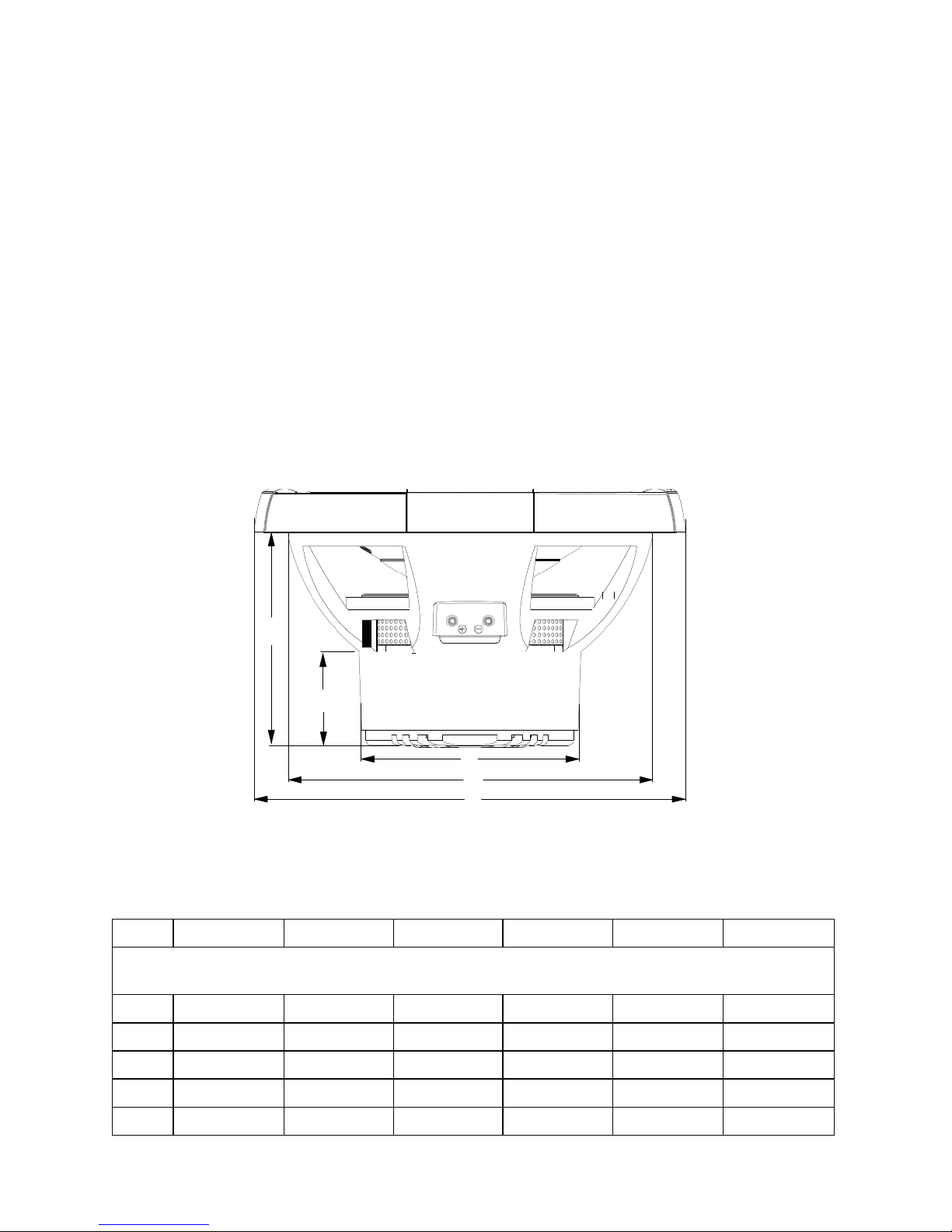
A
B
C
D
E
Figure 13
Figura
13
Abbildung 13
XTRPRO102 XTRPRO104 XTRPRO122 XTRPRO124 XTRPRO152 XTRPRO154
Dimensions inches/mm, Dimensions po/mm, Dimensiones plg./mm, Abmessungen Zoll/mm,
Dimensioni pollici/millimetri, Dimensões polegadas/mm
A
5.87/149
5.87/149
6.46/164
6.46/164
7.49/190
7.49/190
B
2.84/72
2.84/72
2.84/72
2.84/72
2.84/72
2.84/72
C
6.15/156
6.15/156
6.15/156
6.15/156
6.15/156
6.15/156
D
8.87/225
8.87/225
10.91/277
10.91/277
13.87/352
13.87/352
E
10.24/260
10.24/260
12.29/312
12.29/312
15.29/388
15.29/388

© 2012 MD Audio Engineering—all rights reserved
17
Explanation of Enclosure Specifications
There are many different factors that help determine the best style of enclosure for
you or your vehicle. Listed below are some factors that should be considered.
The size of the enclosure is directly proportional to the efficiency and power handling
of that speaker. A woofer in a smaller enclosure will handle more power than the
same woofer in a larger enclosure. The exact opposite is true for efficiency, a larger
enclosure will play lower frequencies at a louder volume with less power than a
smaller enclosure.
The following will explain differences in sealed enclosures. A large enclosure is
best suited if you have smaller amounts of power (25% to 50% of speaker’s power
handling), have a larger vehicle or looking for greater output. While the smaller
enclosure should be utilized if you have recommended power (50% to 100% of
speaker’s rated power handling), have a smaller (high gain) vehicle or are looking for
more accurate sound reproduction. A smaller sealed enclosure will yield more control,
this audible translates into faster and more accurate bass.
A vented enclosure will offer greater efficiency and stronger low bass output compared
to a sealed design. A vented enclosure uses the back wave (sound from the back side
of the cone) to reinforce the output from the speaker. A properly tuned enclosure will
yield gain across the entire bandwidth of the subwoofer system and offer more cone
control than a sealed enclosure. A low tuning will yield less overall gain but greater
extension (low bass). A high tuned enclosure will offer more gain but limit the low
end response of the system. One of the advantages of having a vented enclosure is
because it is tunable to a specific frequency and that tuning frequency is known as the
“Fb”. Another important box specification is “F3”, which is the roll-off frequency at
which the driver's response is down -3dB. This is an important number when it comes
to setting your high-pass filter or your ORION Intelli-Q. The Intelli-Q should be set at
the same frequency as the “F3”as this will keep the speaker from damaging or what
is know as over-loading.
Good planning and proper construction will assure the best response from your
system. The next pages will outline many different enclosures and designs that allow
the XTRPRO subwoofers to perform best. As always, if you have any questions on
enclosure construction or design, call Technical Support 1-800-753-0800.
18
© 2012 MD Audio Engineering—all rights reserved
ENCLOSURE RECOMMENDATIONS
Enclosure Details
1. External dimensions calculated for 3/4” building material
2. Includes speaker displacement
3. Volumes given are net tuning volume
4. Enclosures include a minimal amount of damping material. Just enough material to
line the inside of the enclosure is required.
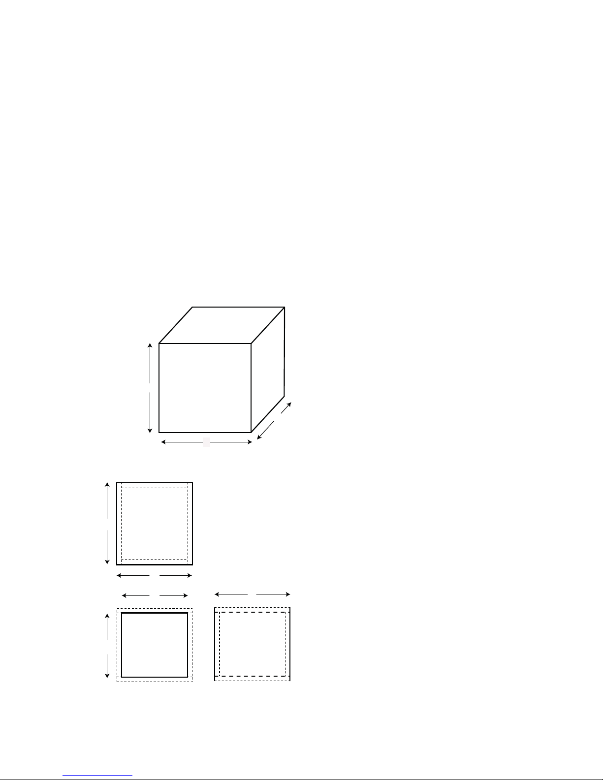
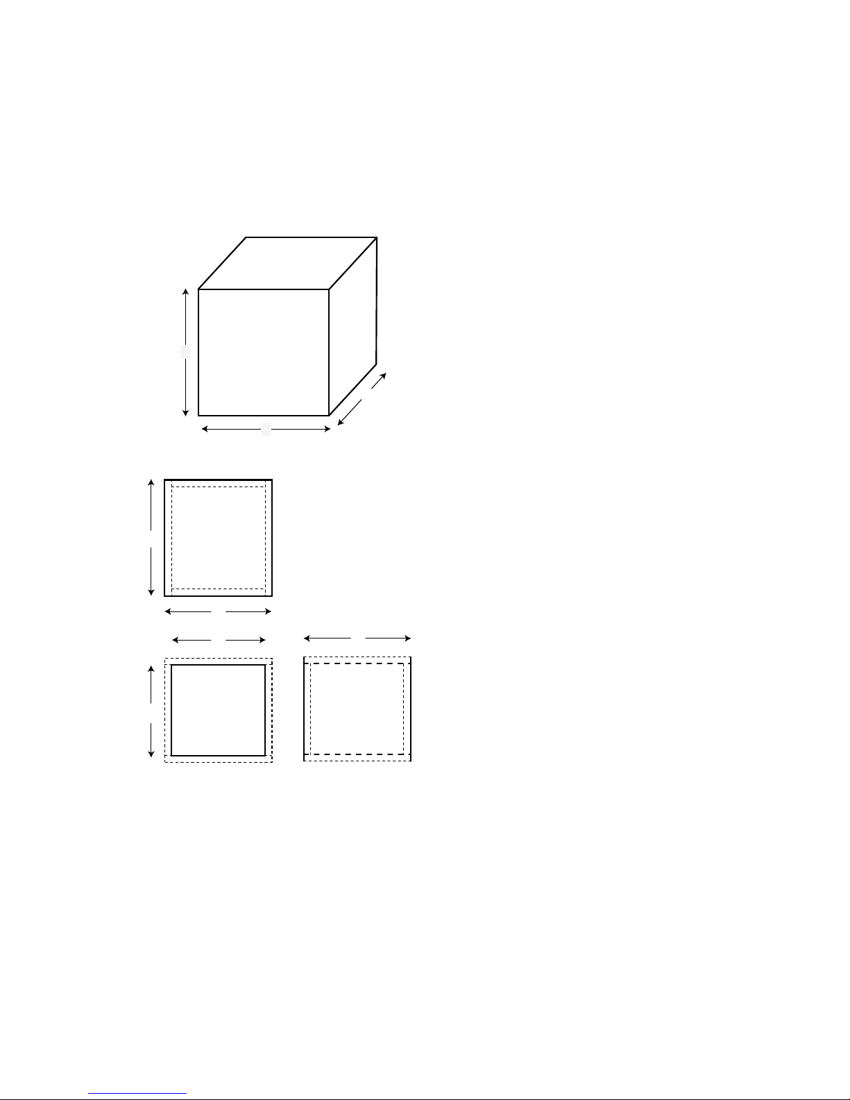
XTRPRO102 & 104 Sealed Enclosure Recommendations
Box
Properties
— Description
—
Type:
Closed
Box
Shape: Prism,
Square
— Box Parameters —
Vb = 0.75
cu.ft
V(total) = 0.791
cu.ft
Qtc =
0.598
QL =
7
F3 = 50.61
Hz
Fill =
none
External
Dimensions
A = 12 in. (305
mm)
B = 15.5 in. (394
mm)
C = 10.8 in. (274
mm)
Internal
Dimensions
A = 10.5 in. (267
mm)
A
B = 14 in. (356
mm)
C = 9.3 in. (236
mm)
C
Wall
Thickness
Front = 0.75 in. (19
mm)
B Side = 0.75 in. (19
mm)
c
Top
&
Bottom
b
d
Front &
a
Back
c
Sides
—Box
Parts—
Box Shape: Square
Prism
1 Top, 1
Bottom:
depth (c) = 10.8 in. (274
mm)
width (b) = 15.5 in. (394
mm)
thickness = 0.75 in. (19
mm)
1 Front, 1
Back:
height (a) = 10.5 in. (267
mm)
width (d) = 14 in. (356
mm)
thickness = 0.75 in. (19
mm)
2 Sides: height (a) = 10.5 in. (267
mm)
depth (c) = 10.8 in. (274
mm)
thickness = 0.75 in. (19
mm)
Figure 14
Figura
14
Abbildung
14
—Driver
Mounting—
Mounting:
Front
© 2012 MD Audio Engineering—all rights reserved
19
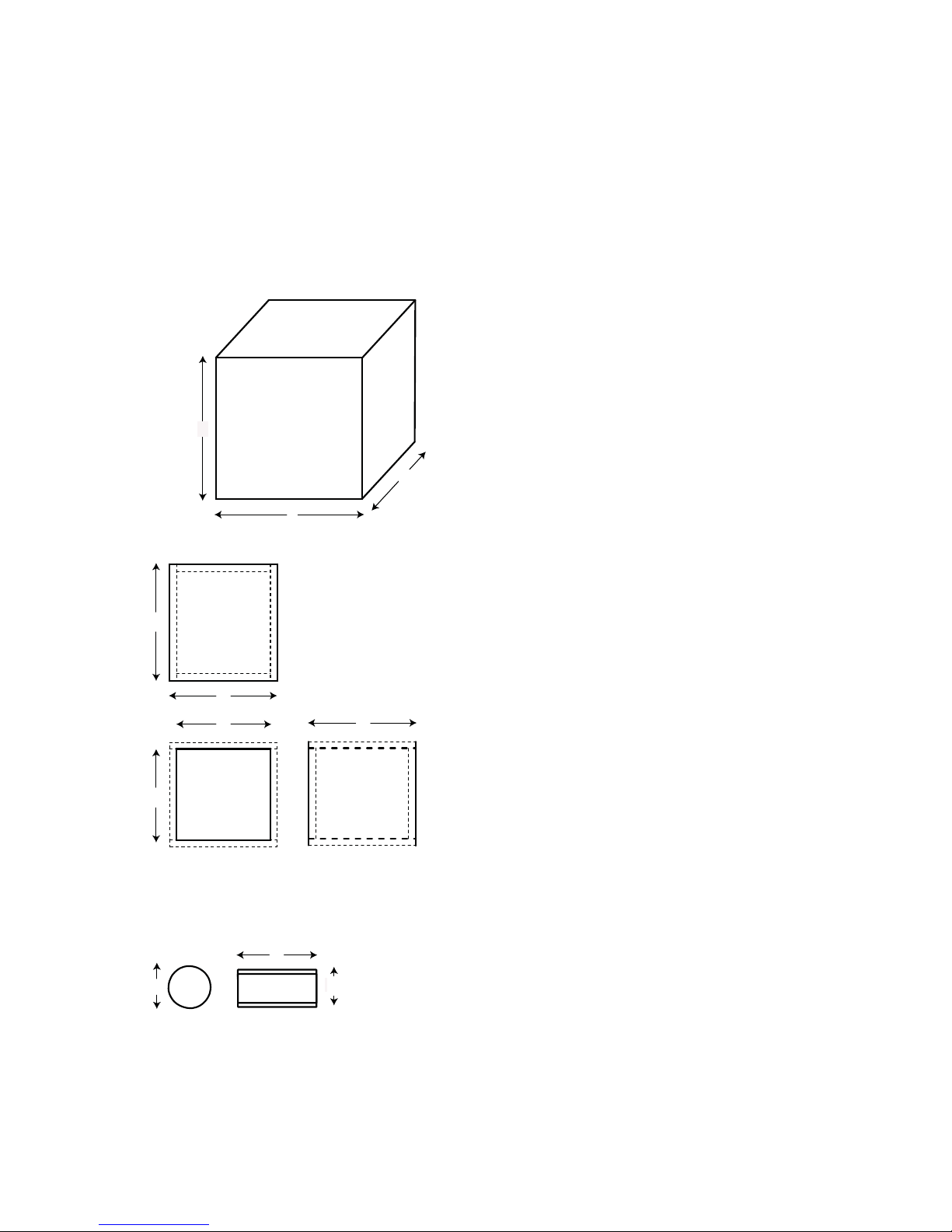
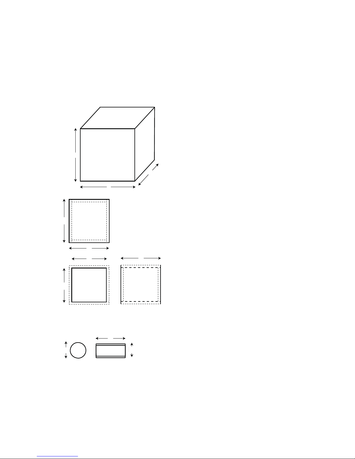
XTRPRO102 & 104 Vented Enclosure Recommendations
Box
Properties
— Description
—
Type:
Vented
Box
Shape: Prism,
Square
— Box Parameters —
Vb = 0.75
cu.ft
V(total) = 0.841
cu.ft
Fb = 44 Hz
QL =
7
F3 = 35.24
Hz
Fill =
none
— Vents —
No. of Vents =
1
Vent shape =
round
Vent ends = one
flush
Dv = 3 in. (76
mm)
Lv = 11.19 in. (284
mm)
Figure 15
Figura
15
Abbildung
15
A
B
External
Dimensions
A = 12 in. (305
mm)
B = 15.5 in. (394
mm)
C = 11.39 in. (289
mm)
Internal
Dimensions
A = 10.5 in. (267
mm)
B = 14 in. (356
mm)
C = 9.89 in. (251
mm)
C
Wall
Thickness
Front = 0.75 in. (19
mm)
Side = 0.75 in. (19
mm)
c
Top
&
Bottom
b
d
Front
&
a
Back
h
e
c
Sides
g
—Box
Parts—
Box Shape: Square
Prism
1 Top, 1
Bottom:
depth (c) = 11.39 in. (289
mm)
width (b) = 15.5 in. (394
mm)
thickness = 0.75 in. (19
mm)
1 Front, 1
Back:
height (a) = 10.5 in. (267
mm)
width (d) = 14 in. (356
mm)
thickness = 0.75 in. (19
mm)
height (a) = 10.5 in. (267
mm)
depth (c) = 11.39 in. (289
mm)
thickness = 0.75 in. (19
mm)
—Driver
Mounting—
Mounting:
Front
Vent
Parts
1
Duct:
outside diameter (e) = 3.25 in. (83
mm)
inside diameter (g) = 3 in. (76
mm)
length (h) = 11.19 in. (284
mm)
20
© 2012 MD Audio Engineering—all rights reserved
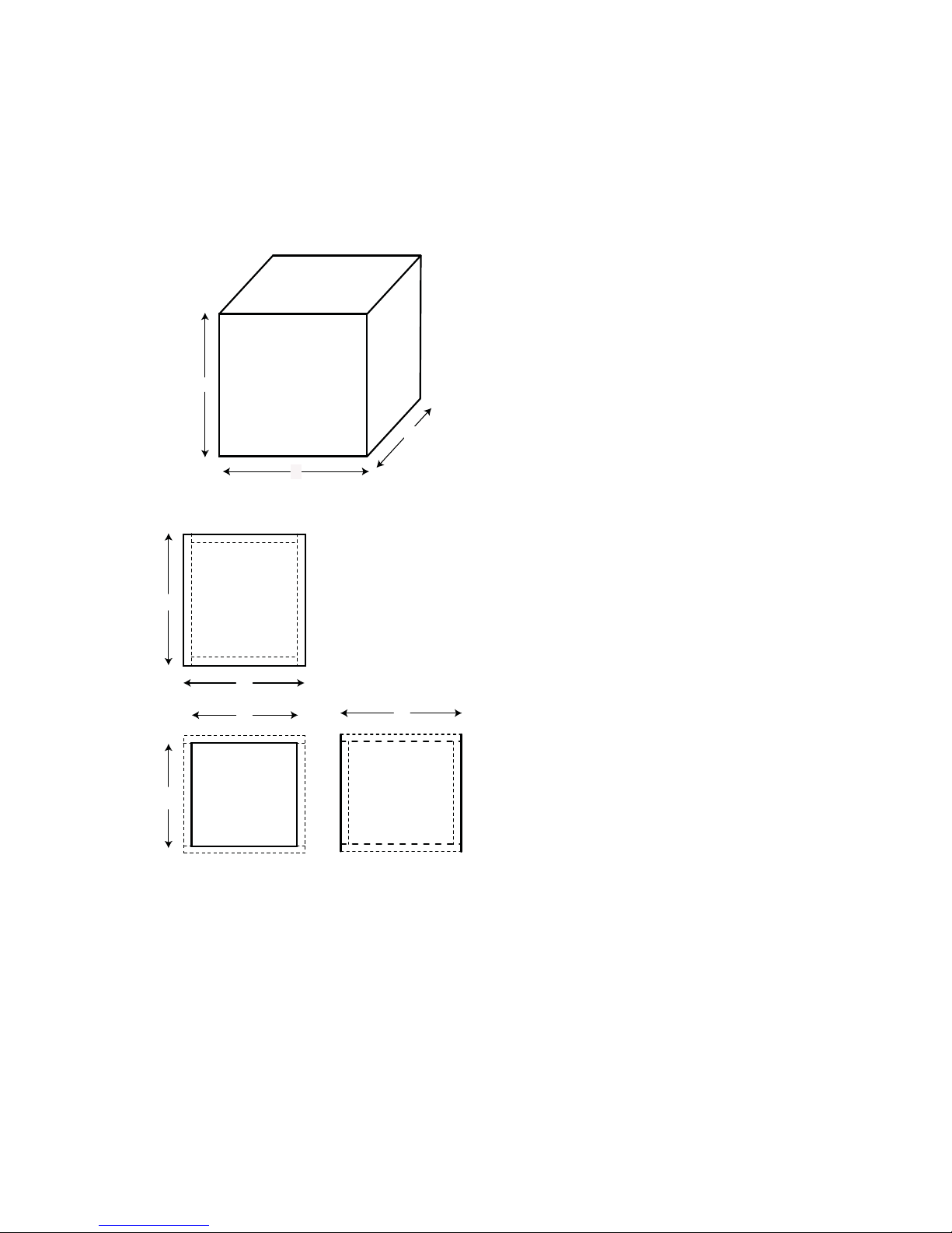
XTRPRO122 & 124 Sealed Enclosure Recommendations
Box
Properties
— Description
—
Type:
Closed
Box
Shape: Prism,
Square
— Box Parameters —
Vb = 1.5
cu.ft
V(total) = 1.55
cu.ft
Qtc =
0.717
QL =
6.886
F3 = 43.09
Hz
Fill =
none
External
Dimensions
A = 16 in. (406
mm)
B = 16 in. (406
mm)
C = 14.24 in. (362
mm)
Internal
Dimensions
A = 14.5 in. (368
mm)
A
B = 14.5 in. (368
mm)
C = 12.74 in. (324
mm)
C
Wall
Thickness
Front = 0.75 in. (19
mm)
B Side = 0.75 in. (19
mm)
c
Top
&
Bottom
b
d
Front &
a
Back
c
Sides
—Box
Parts—
Box Shape: Square
Prism
1 Top, 1
Bottom:
depth (c) = 14.24 in. (362
mm)
width (b) = 16 in. (406
mm)
thickness = 0.75 in. (19
mm)
1 Front, 1
Back:
height (a) = 14.5 in. (368
mm)
width (d) = 14.5. (368
mm)
thickness = 0.75 in. (19
mm)
2
Sides:
height (a) = 14.5 in. (368
mm)
depth (c) = 14.24 in. (362
mm)
thickness = 0.75 in. (19
mm)
Figure 16
Figura
16
Abbildung
16
—Driver
Mounting—
Mounting:
Front
© 2012 MD Audio Engineering—all rights reserved
21
XTRPRO122 & 124 Vented Enclosure Recommendations
Box
Properties
— Description
—
Type:
Vented
Box
Shape: Prism,
Square
— Box Parameters — Vb
=
1.5 cu.ft
V(total)
=
1.637
cu.ft
Fb = 40
Hz
QL =
6.886
F3 = 32.19
Hz
Fill =
none
— Vents —
No. of Vents =
1
Vent shape =
round
Vent ends = one
flush
Dv = 4 in. (102
mm)
Lv = 11.26 in. (286
mm)
Figure 17
Figura
17
Abbildung
17
A
B
External
Dimensions
A = 13.5 in. (343
mm)
B = 18.5 in. (470
mm)
C = 15.36 in. (390
mm)
Internal
Dimensions
A = 12 in. (305
mm)
B = 17 in. (432
mm)
C = 13.86 in. (352
mm)
C
Wall
Thickness
Front = 0.75 in. (19
mm)
Side = 0.75 in. (19
mm)
c
Top
&
Bottom
b
d
Front
&
a
Back
h
e
c
Sides
g
—Box
Parts—
Box Shape: Square
Prism
1 Top, 1
Bottom:
depth (c) = 15.36 in. (390
mm)
width (b) = 18.5 in. (470
mm)
thickness = 0.75 in. (19
mm)
1 Front, 1
Back:
height (a) = 12 in. (305
mm)
width (d) = 17 in. (432
mm)
thickness = 0.75 in. (19
mm)
height (a) = 12 in. (305
mm)
depth (c) = 15.36 in. (390
mm)
thickness = 0.75 in. (19
mm)
—Driver
Mounting—
Mounting:
Front
Vent
Parts
1
Duct:
outside diameter (e) = 4.25 in. (108
mm)
inside diameter (g) = 4 in. (102
mm)
length (h) = 11.26 in. (286
mm)
22
© 2012 MD Audio Engineering—all rights reserved
XTRPRO152 & 154 Sealed Enclosure Recommendations
Box Properties
— Description —
Type: Closed Box
Shape: Prism, Square
— Box Parameters — Vb
= 2 cu.ft
V(total)
=
2.078 cu.ft
Qtc = 0.963
QL = 5.281
F3 = 37.55 Hz
Fill = none
External Dimensions
A = 17.5 in. (445 mm)
B = 17.5 in. (445 mm)
C = 15.52 in. (394 mm)
Internal Dimensions
A = 16 in. (406 mm)
A
B = 16 in. (406 mm)
C = 14.02 in. (356 mm)
C
Wall Thickness
Front = 0.75 in. (19 mm)
B
Side = 0.75 in. . (19 mm)
c
Top &
Bottom
b
d
Front &
a
Back
c
Sides
—Box Parts—
Box Shape: Square Prism
1 Top, 1 Bottom:
depth (c) = 15.52 in. (394 mm)
width (b) = 17.5 in. (445 mm)
thickness = 0.75 in. (19 mm)
1 Front, 1 Back:
height (a) = 16 in. (406 mm)
width (d) = 16 in. (406 mm)
thickness = 0.75 in. (19 mm)
2 Sides:
height (a) = 16 in. (406 mm)
depth (c) = 15.52 in. (394 mm)
thickness = 0.75 in. (19 mm)
Figure 18
Figura 18
Abbildung
18
—Driver Mounting—
Mounting: Front
 Loading...