

Orion XTRPRO102, XTRPRO104, XTRPRO122, XTRPRO124, XTRPRO152 Owner's Manual
...
Subwoofer
MODEL
XTRPRO102
XTRPRO104
XTRPRO122
XTRPRO124
XTRPRO152
XTRPRO154
OWNER'S MANUAL

FEATURES
1 2
3
15
4
14
13
5
12
11
6
7
Figure
1
Figura
1
Abbildung
1
10 9
8
1
Polypropylene dust cap - moisture and UV resistant.
2
Oversized NBR (Nitrile-butadiene Rubber) surround for linear controlled
long excursion.
3
Paper cone - moisture and UV resistant.
4 Custom cast aluminum frame.
5
Vented Aluminum voice coil former (2.5" voice coil former).
6
8mm steel front plate.
7
Large 2 stack ceramic magnets.
8
8mm steel back plate/pole piece T yoke assembly.
9
1.125"
vent. Part of the enhanced voice coil cooling system (forced
convection).
10 PVC magnet protector.
11
High temperature Copper dual 2 ohm or dual 4 ohm voice coil.
12
Venting in voice coil former. Part of the enhanced voice coil cooling system
(forced convection).
1
3 Dual Interlaced Conex spider with stitched and looped tinsel leads
attached.
14 Custom terminal blocks.
15 ABS Trim Ring.
2 ohm
2 ohm
2 ohm
2 ohm
WIRING CONFIGURATIONS
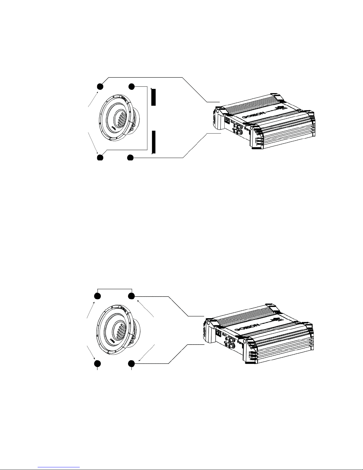
Series - One Speaker (dual 2 ohm voice coils)
One dual 2 ohm voice coil woofer with voice coils in connected in series results in a 4
ohm load to the amplifier.
_ _
_
+
Figure
2
Figura
2
Abbildung 2
+ +
1. Connect the woofer in series by connecting the negative (-) of one terminal to the
positive (+) terminal of the other coil.
2. Wire the positive (+) terminal of the first coil to the positive (+) terminal on the
amplifier. Wire the negative (-) terminal of the second coil to the negative (-)
terminal on the amplifier.
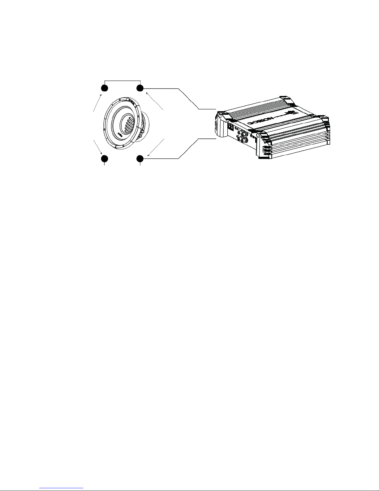
Parallel—One Speaker (dual 2 ohm voice coils)
One dual 2 ohm voice coil woofer with voice coils in parallel results in a 1 ohm load
to the amplifier.
_
_
_
Figure 3
+
Figura 3
+ +
Abbildung
3
1. Connect the speaker in parallel by connecting the two positive (+) terminals
together and the two negative (-) terminals together.
2. Wire the positive (+) terminals of the woofer to the positive (+) terminal on
the amplifier. Wire the negative (-) terminals of the woofer to the negative (-)
terminal on the amp.
4 ohm
4 ohm
Parallel — One Speaker (dual 4 ohm voice coils)
One dual 4 ohm voice coil woofer with voice coils in parallel results in a 2 ohm load
to the amplifier.
_
_
_
Figure 4
+
Figura 4
+ +
Abbildung
4
1. Connect the speaker in parallel by connecting the two positive (+) terminals
together and the two negative (-) terminals together.
2. Wire both positive (+) terminals of the woofer to the positive (+) terminal on
the amplifier. Wire both negative (-) terminals of the woofer to the negative (-)
terminal on the amplifier.
4 ohm
4 ohm
4 ohm
4 ohm
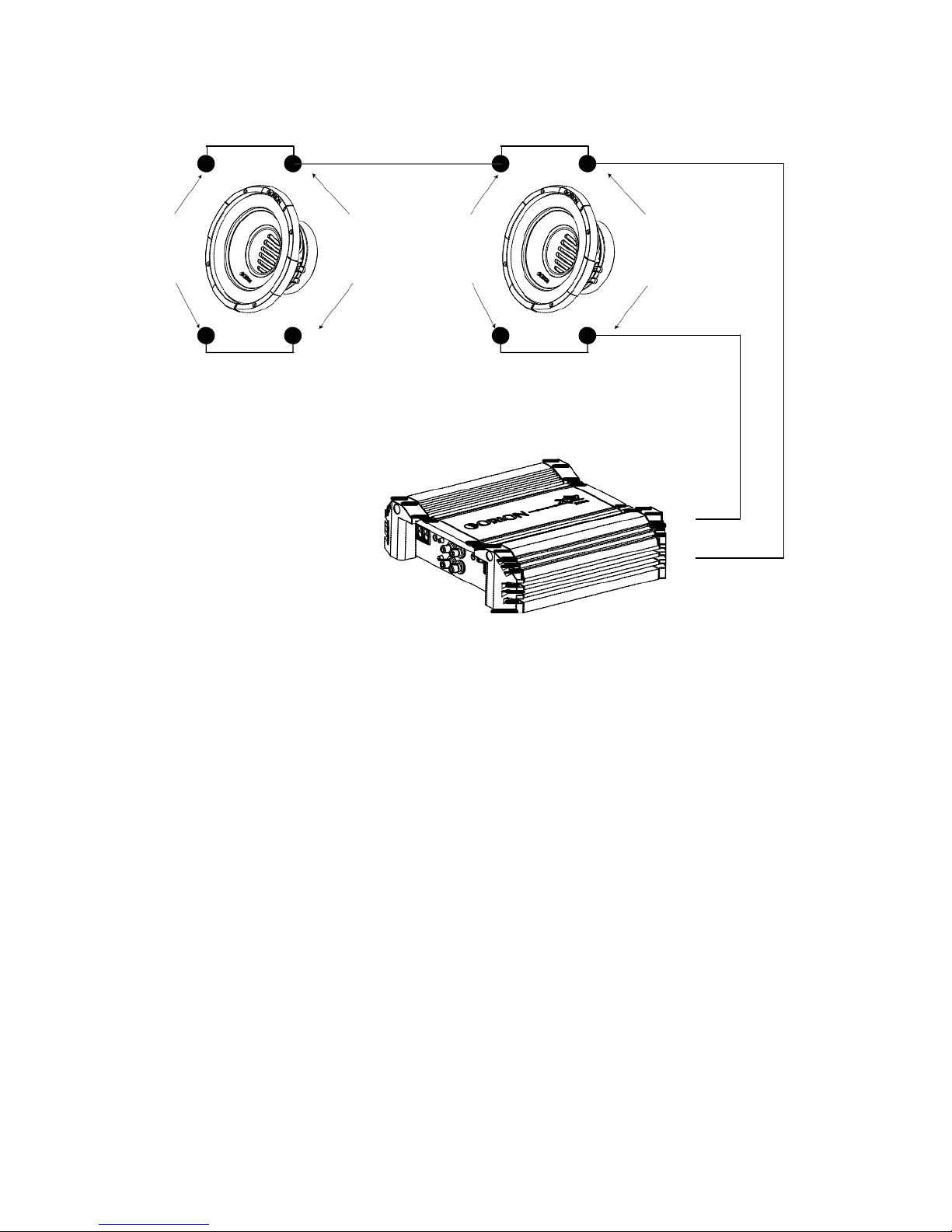
Parallel - Two Speaker (dual 4 ohm voice coils)
Two dual 4 ohm voice coil woofers with voice coils in parallel and the two woofers in
parallel results in a
1
ohm load to the amplifier.
- - - -
+
+
+
+
Figure 5
+
Figura 5
Abbildung 5
-
1. Connect the speaker in parallel by connecting the four positive (+) terminals
together and the four negative (-) terminals together.
2. Wire the positive (+) terminals of the woofers to the positive (+) terminal on
the amplifier. Wire the negative (-) terminals of the woofers to the negative (-)
terminal on the amplifier.
2 ohm
2 ohm
2 ohm
2 ohm
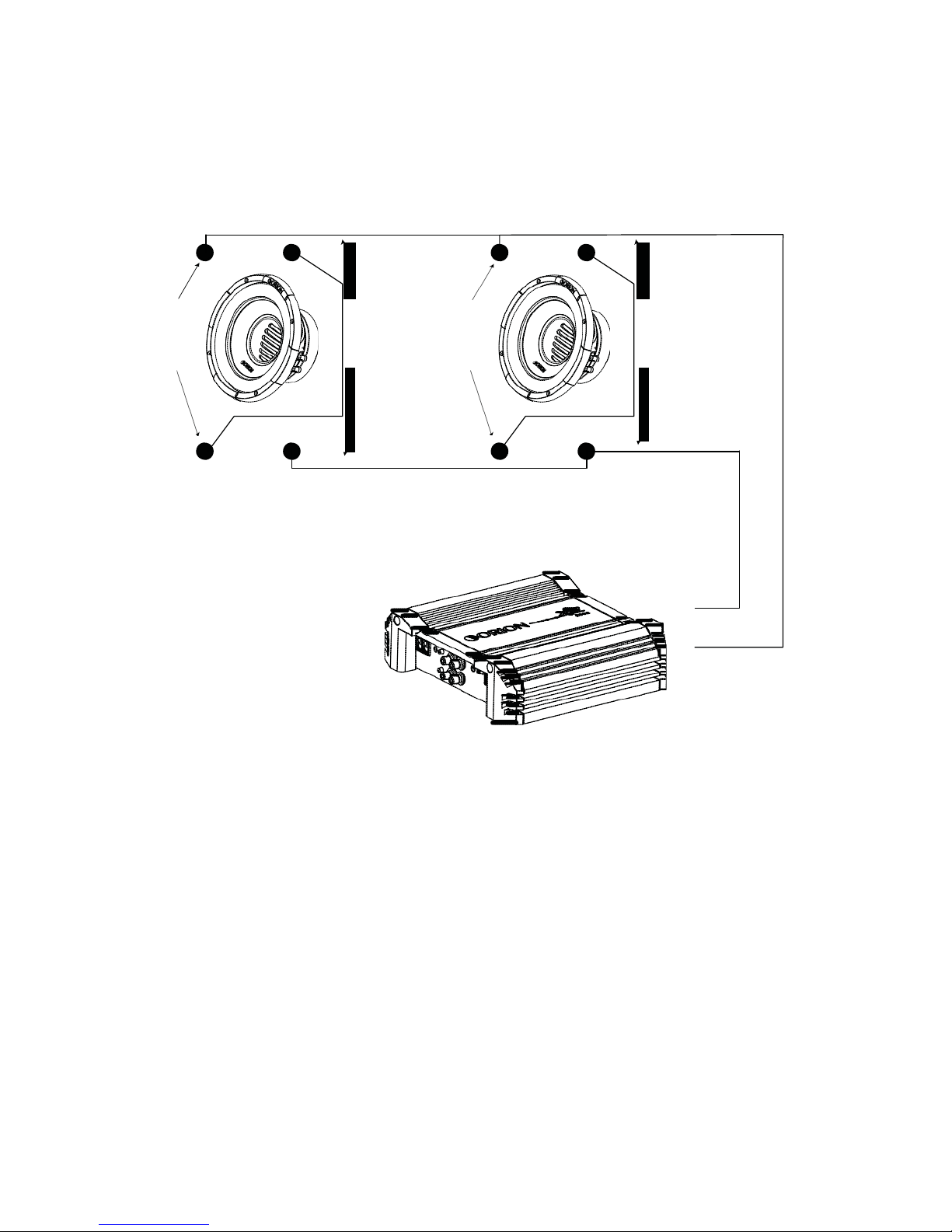
Series/Parallel - Two Speakers (dual 2 ohm voice coils)
Note: Verify and ensure that the woofer wiring is connected as shown with
the negative connection from the first woofer coil connected to the positive
connection of the second woofer coil.
Two dual 2 ohm voice coil woofers with voice coils in series and then parallel the two
series woofers results in a 2 ohm load to the amplifier.
- - - -
+
+
+
+
Figure 6
+
Figura 6
Abbildung 6
-
1. Connect each woofer in series by connecting the negative (-) of the first coil to the
positive (+) terminal of the second coil.
2. Wire the positive (+) terminal of the first coil on each woofer to the positive (+)
terminal on the amplifier. Wire the negative (-) terminal of the second coil on
each woofer to the negative (-) terminal on the amplifier.
4
ohm
4
ohm
4
ohm
4
ohm
4
ohm
4
ohm
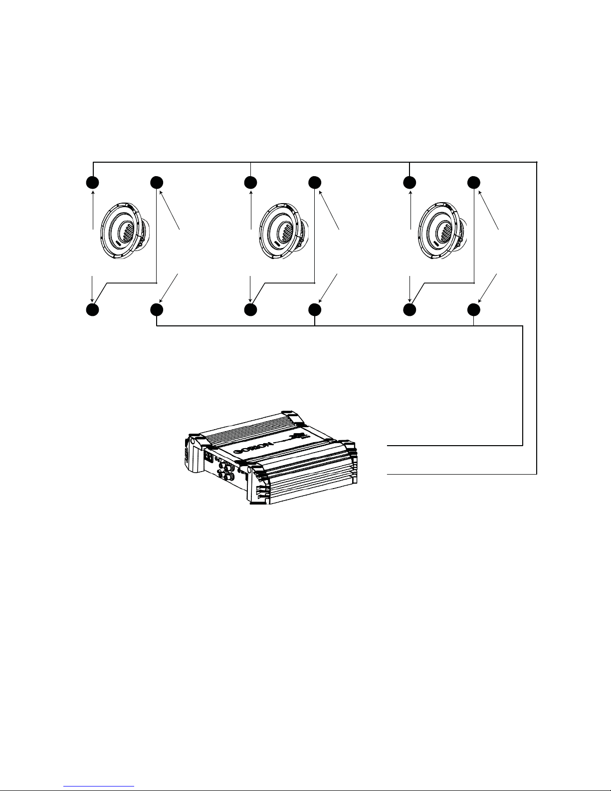
Series/Parallel - Three Speakers (dual 4 ohm voice coils)
Note: Verify and ensure that the woofer wiring is connected as shown with
the negative connection from the first woofer coil connected to the positive
connection of the second woofer coil.
Three dual 4 ohm voice coil woofer with voice coils of each woofer wired in series and
then parallel the three woofers for a resulting 2.67 ohm load to the amplifier.
- - - - -
-
+
+
+
+
+
+
Figure 7
+
Figura
7
Abbildung 7
-
1. Connect each woofer in series by connecting the negative (-) of the first coil to the
positive (+) terminal of the second coil.
2. Wire the positive (+) terminal of each woofer’s first coil to the positive (+) terminal
on the amplifier. Wire the negative (-) terminal of each woofer’s second coil to the
negative (-) terminal on the amplifier.
 Loading...