

Orion XTR500.4, XTR750.4, XTR1000.4, XTR2500.4, XTR1700.4 Owner's Manual
Amplifier
OWNER'S MANUAL
MODEL
XTR500.4
XTR750.4
XTR1000.4
XTR2500.4
XTR1700.4

CONTENTS
Amplifier Wiring. . . . . . . . . . . . . . . . . . . . . . . . . . 8
Power Connections . . . . . . . . . . . . . . . . . . . . . . . . . . . 8
Speaker Connections XTR500.4, XTR750.4, XTR1000.4
XTR1700.4 and XTR2500.4 . . . . . . . . . . . . . . . . 8 ~ 10
Amplifier Installation . . . . . . . . . . . . . . . . . . . . . . 11
Choosing Mounting Locations . . . . . . . . . . . . . . . . . . 11
Passenger Compartment. . . . . . . . . . . . . . . . . . . . . . . 11
Trunk Compartment. . . . . . . . . . . . . . . . . . . . . . . . . . 11
General Precautions and Installation Tips . . . . . . 11 ~ 12
Tools of the Trade . . . . . . . . . . . . . . . . . . . . . . . . . . . 12
Step By Step Installation . . . . . . . . . . . . . . . . . . . . . . 13
Set Up and Troubleshooting. . . . . . . . . . . . . . . . . 14
Testing the System. . . . . . . . . . . . . . . . . . . . . . . . . . . 14
Adjusting the Sound of the System . . . . . . . . . . . 14 ~ 15
Amplifier Visual Troubleshooting . . . . . . . . . . . . 15 ~ 16
Troubleshooting Tips . . . . . . . . . . . . . . . . . . . . . 17 ~ 19
Introduction. . . . . . . . . . . . . . . . . . . . . . . . . . . . . . . 2
What’s in the Box. . . . . . . . . . . . . . . . . . . . . . . . . . . 2
Practice Safe Sound™ . . . . . . . . . . . . . . . . . . . . . . . 2
End Panel Layouts . . . . . . . . . . . . . . . . . . . . . . . 3 ~ 4
Record Your Serial Number And Date . . . . . . . . . 2
CEA Specifications. . . . . . . . . . . . . . . . . . . . . . . . . . 4
Specifications. . . . . . . . . . . . . . . . . . . . . . . . . . . . . . 5
Amplifier Settings . . . . . . . . . . . . . . . . . . . . . . . . . . 6
Signal Input and Output Configurations . . . . . . . . . . . . 6
Level control . . . . . . . . . . . . . . . . . . . . . . . . . . . . . . . . 6
Internal Crossover Configurations, Flat (full range) . . . . 6
Line Output Configurations . . . . . . . . . . . . . . . . . . . . . . 6
Crossover Switch . . . . . . . . . . . . . . . . . . . . . . . . . . . . . 6
Low-Pass Crossover . . . . . . . . . . . . . . . . . . . . . . . . . . . 6
High-Pass Crossover. . . . . . . . . . . . . . . . . . . . . . . . . . 7
Adjusting Bass Boost . . . . . . . . . . . . . . . . . . . . . . . 7
Phase Shift Control . . . . . . . . . . . . . . . . . . . . . . . . . . . . 7
Remote Gain Operation . . . . . . . . . . . . . . . . . . . . . . . . 7

OWNER' S MAN U A L - 2
IN TRODUCTION
WHAT’S IN THE BOX
• (1) Amplifier
• (2) Allen wrenches 2mm & 3mm
• (1) Hardware kit
• (1) Owner’s manual
• (1) Window decal
• (1) Unique individual amplifier birth certificate
PRACTICE SAFE SOUND™
Continuous exposure to sound pressure levels over 100dB may cause
permanent hearing loss. High power automotive sound systems can
generate sound pressure levels in excess of 130dB. When playing
your system at high levels, please use hearing protection and avoid
long term exposure.
Thank you for your purchase of Orion’s amplifier. Each Orion amplifier
is designed to be the leader in its class offering ease of use, advanced
features, and the most power. Orion amplifiers are designed as the best
affordable high end car audio amplifier money can buy. Listed below are
the features of these new Orion amplifiers.
• XTR500.4 -
90 Watts per channel, four-channel amplifier with
built-in high-pass and low-pass 12dB/octave crossover and Bass Boost.
The XTR500.4 is capable of 6, 5, 4, 3 or 2 channel operation with a
maximum power capability of 500 Watts RMS into two 4Ω Bridged Loads.
• XTR750.4 -
135 Watts per channel, four-channel amplifier with
built-in high-pass and low-pass 12dB/octave crossover and Bass Boost.
The XTR750.4 is capable of 6, 5, 4, 3 or 2 channel operation with a
maximum power capability of 750 Watts RMS into two 4Ω Bridged Loads.
• XTR1000.4 -
165 Watts per channel, four-channel amplifier with
built-in high-pass and low-pass 12dB/octave crossover and Bass Boost.
The XTR1000.4 is capable of 6, 5, 4, 3 or 2 channel operation with a
maximum power capability of 1000 Watts RMS into two 4Ω Bridged Loads.
• XTR1700.4 -
250Watts per channel, four-channel amplifier with
built-in high-pass and low-pass 12dB/octave crossover and Bass Boost.
The XTR1700.4 is capable of 6, 5, 4, 3 or 2 channel operation with a
maximum power capability of 1700 Watts RMS into two 4Ω Bridged Loads.
• XTR2500.4
400Watts per channel, four-channel amplifier with
built-in high-pass and low-pass 12dB/octave crossover and Bass Boost.
The XTR2500.4 is capable of 6, 5, 4, 3 or 2 channel operation with a
maximum power capability of 2500 Watts RMS into two 4Ω Bridged Loads.
The installation of all Orion components will determine the overall
performance result. Improper installation will not only limit the
performance of your Orion system but also potentially compromise
the reliability of this amplifier. To ensure proper sonic results and
component reliability, please refer to your authorized Orion dealer
for installation assistance or advice. If you decide to perform the
installation yourself, be sure to read the entire manual before beginning the installation.
• (1) Remote Kit (Remote Gain Control with cable)
OWNER' S MAN U A L - 3
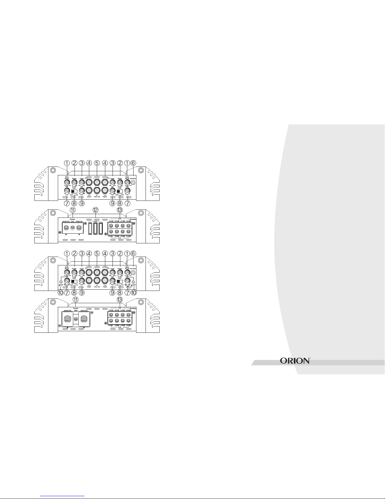
END PANEL LAYOUTS
help compensate for timing differences between drivers.
3. Level Control (Channels 1 & 2 / 3 & 4) - continuous adjustment
for full power output
4. RCA Input (Channels 1 & 2 / 3 & 4) - accepts Low Level RCA
Inputs (200mV-4V) from a head unit, preamplifier, or equalizer.
5. RCA Line Output - provides easy connection to additional ampl-
ifiers. Note that some OEM stereo headunits may sense the
attached load and may turn off their speaker outputs if expected
load conditions aren’t achieved
6. Remote Gain input - connects remote gain control to control the
bass level from the driver’s seat.
7. High pass filter (Channels 1 & 2 / 3 & 4) - adjusts the frequency
of the crossover for the HPF (High-Pass Frequency Control ,
XTR500.4,XTR750.4 and XTR1000.4 : 50Hz - 5kHz ,
XTR1700.4 and XTR2500.4 : 50Hz-1.5kHz/500Hz-15kHz)
8. X-Over (cross-over Channels 1 & 2 / 3 & 4) - activates LPF (low
pass crossover), Full (all pass), or HPF (high pass crossover)
9. Low pass filter (Channels 1 & 2 / 3 & 4) - adjusts the frequency of
the crossover for the LPF (Low-Pass Frequency Control ,
10. Variable High pass filter X10 Feature - XTR1700.4 and
XTR2500.4 50Hz-1.5kHz(Without pressing a button)/
500Hz-15kHz(press a button).
50Hz -400Hz)
11. Power connection input
* NEGATIVE(GND) - power return connection. Connect this
terminal directly to the sheet metal chassis of the vehicle, using
the shortest wire necessary to make this connection. Always use
wire of the same gauge or larger than the (+) 12 volt power wire.
The chassis connection point should be scraped free of paint
Figure 1
1. Bass Boost (Channels 1 & 2 / 3 & 4) - continuously adjusts
from 0 to 18dB of boost centered at 45Hz
2. Phase Shift Control (Channels 1 & 2 / 3 & 4) - Allows you to
change the phase of your subwoofer from 0 to 180 degrees to
XTR500.4,XTR750.4 and XTR1000.4
XTR1700.4 and XTR2500.4
.
.
OWNER' S MAN U A L - 4
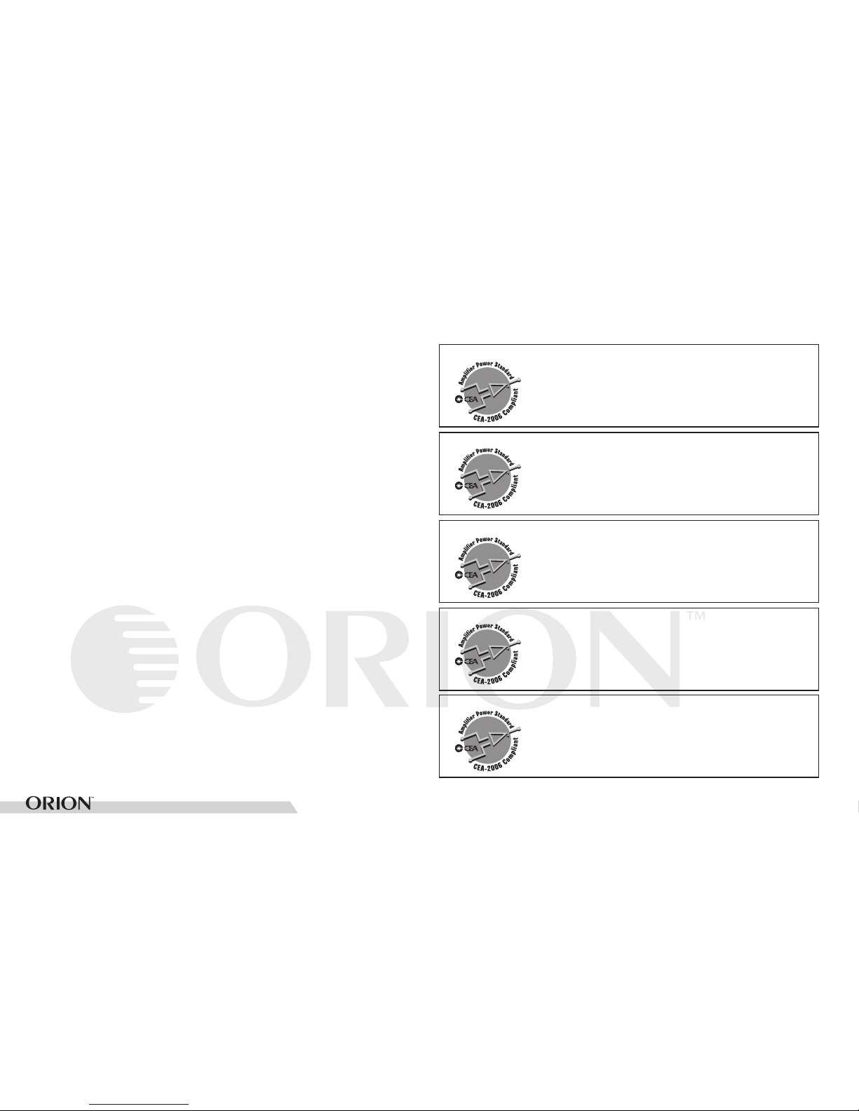
CEA SPECIFICATION S
Power Output: 90 Watts RMS x 4 at 4 ohms and
< 1% THD+N
Signal to Noise Ratio: >70 dBA (reference 1 Watt
into 4 ohms)
Additional Power: 125 Watts RMS x 4 at 2 ohm
and < 1% THD+N
XTR500.4
Power Output: 135 Watts RMS x 4 at 4 ohms and
< 1% THD+N
Signal to Noise Ratio: >70 dBA (reference 1 Watt
into 4 ohms)
Additional Power: 188 Watts RMS x 4 at 2 ohm
and < 1% THD+N
XTR750.4
Power Output: 165 Watts RMS x 4 at 4 ohms and
< 1% THD+N
Signal to Noise Ratio: >70 dBA (reference 1 Watt
into 4 ohms)
Additional Power: 250 Watts RMS x 4 at 2 ohm
and < 1% THD+N
XTR1000.4
Power Output: 250 Watts RMS x 4 at 4 ohms and
< 1% THD+N
Signal to Noise Ratio: >70 dBA (reference 1 Watt
into 4 ohms)
Additional Power: 425 Watts RMS x 4 at 2 ohm
and < 1% THD+N
XTR1700.4
Power Output: 400 Watts RMS x 4 at 4 ohms and
< 1% THD+N
Signal to Noise Ratio: >70 dBA (reference 1 Watt
into 4 ohms)
Additional Power: 625 Watts RMS x 4 at 2 ohm
and < 1% THD+N
XTR2500.4
* REM - this terminal turns on the amplifier when (+) 12 volt is
applied. Connect it to the remote turn on lead of the head unit
or signal source. If a (+) 12 volt remote turn lead is not available,
a Remote Power Adapter (P/N #ORRPA) can be used to supply a
12. Fuse - XTR500.4(40Ax2),XTR750.4(30Ax3),XTR1000.4(40Ax3),
XTR1700.4(None),XTR2500.4(None)
13. Speakers - connect the speakers to these terminals.
(refer to the Speaker Connection section of this manual)
remote turn on signal. DO NOT connect this terminal to constant
and dirt. Use only quality crimped and/or soldered connectors
at both ends of this wire.
DO NOT connect this terminal directly to the vehicle
battery ground terminal or any other factory ground points
(+) 12 volt
* POSITIVE(+BAT) - cconnect this terminal through a FUSE or
CIRCUIT BREAKER to the positive terminal of the vehicle battery
or the positive terminal of an isolated audio system battery
WARNING : Always protect this power wire by installing a fuse
or circuit breaker of the appropriate size within 12 inches of the
battery terminal connection.
OWNER' S MAN U A L - 5
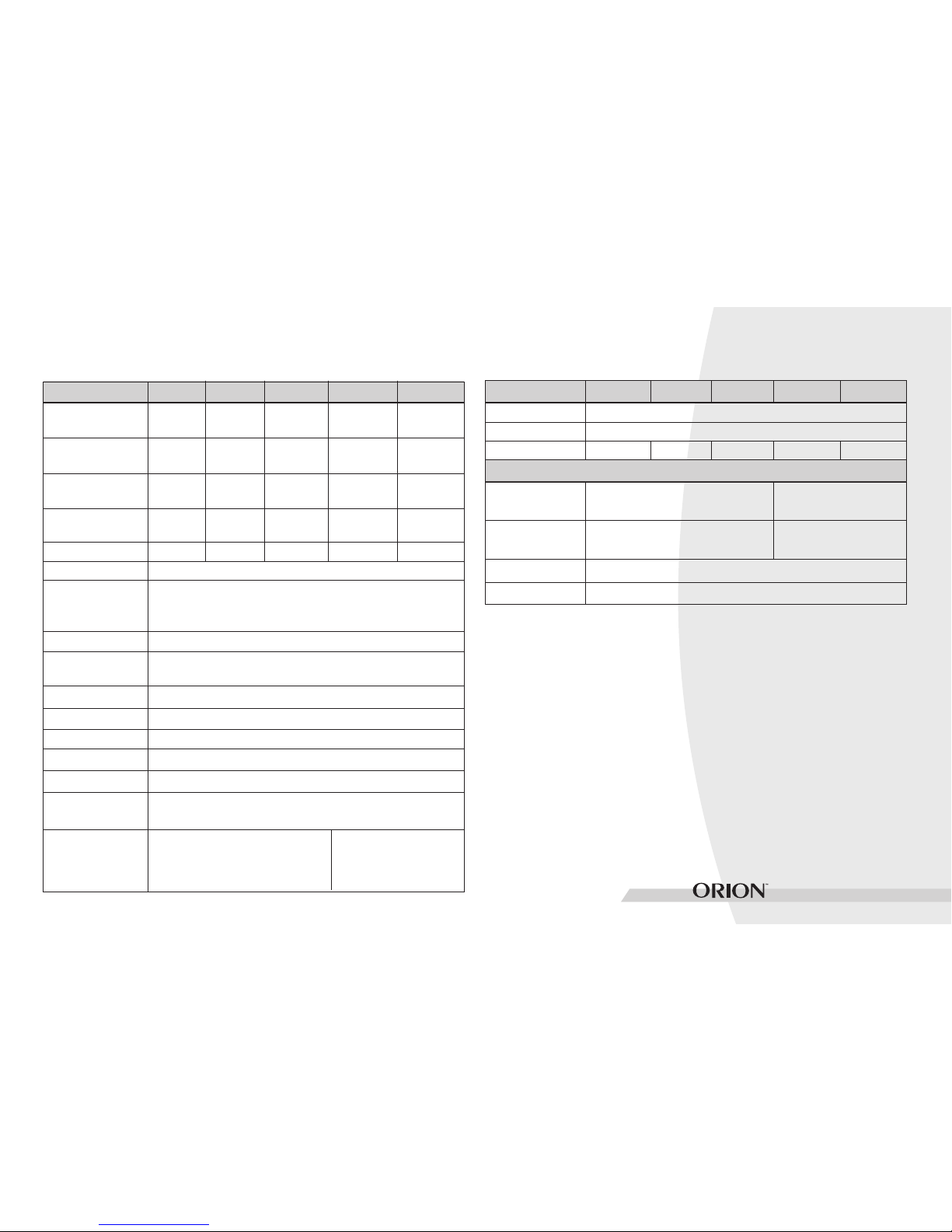
SPECIFICATIONS
Amplifier Section XTR500.4 XTR750.4 XTR1000.4 XTR1700.4
Amplifier Efficiency
Externally Bridgeable
Damping Factor
Signal to Noise ratio
at rated output power
and lowest impedance
Power Output 4Ω
(Watts / RMS) *
90 x 4 135 x 4 165 x 4 250 x 4
125 x 4 188 x 4 250 x 4 425 x 4Power Output 2Ω
(Watts / RMS) **
Power Output 4Ω
(Watts / RMS) Bridged
Distortion at Rated
Power
Frequency Response
Linear Bandwidth
250 x 2 375 x 2 500 x 2 850 x 2
Nominal Power Output
4Ω (Watts) Bridged
1000Watts 1500Watts 2000Watts 3400Watts
> 60% into 2 Ω load at max . power
>95dB
No
0.05% THD+N
20Hz to 35kHz +/- 1dB
20Hz to 65kHz +/- 3dB
> 100
XTR2500.4
400 x 4
625 x 4
1250 x 2
5000Watts
2000Watts 3000Watts 4000Watts 6800Watts 10000Watts
MAX Music Power
Input Sensitivity (rms)
Supply Voltage Range
200mV to 4V
9 to 16V
Protection Thermal, DC offset, reverse polarity, short
protection, under-voltage, over-voltage
Amplifier Section XTR500.4 XTR750.4 XTR1000.4 XTR1700.4
Crossover Section
Balanced Line Inputs
Terminal Wire Gauge
Low Pass Crossover
Power 4 AWG
Remote 10 AWG
Ground 4 AWG
Speaker 10 AWG
Power 0 AWG
Remote 10 AWG
Ground 4 AWG
Speaker 10 AWG
Yes
20kΩ
Continuously variable
(50-400Hz)
Dimensions (inches)
10.3 x 9.3 x 2.5 11.5 x 9.3 x 2.5 14.3 x 9.3 x 2.5 17.4 x 9.3 x 2.5
XTR2500.4
21.3 x 9.3 x 2.5
Phase shift control
Input Impedance
Continuously variable
(50-400Hz)
High Pass Crossover Continuously variable
(50-5kHz)
Continuously variable
(50-1.5kHz/500-15kHz)
Bass Boost 0-18dB variable
* Continuous 4 Ω load 20Hz to 20kHz, < 1% THD, with input
voltage at 14.4 VDC.
** Continuous 2 Ω load 20Hz to 20kHz, < 1% THD, with input
voltage at 14.4 VDC.
0˚ to 180˚

OWNER' S MAN U A L - 6
AMPLIFIER SET TINGS
Signal Input and Output Configurations
The input section of the amplifier consists of gain controls, high pass
and low pass crossovers controls, Bass Boost control and RCA inputs
and outputs. The input section makes it easy to adapt this amplifier
to most system configurations.
Level Control
These Orion amplifiers have level adjustments to allow for easy
integration with any source unit. The input sensitivity can be
adjusted from 200mV to 8V. Refer to Testing the System and Adjusting the Sound of the System sections of this manual for detailed
instructions on setting the gain.
Line Output Configurations
The line outputs on Orion amplifiers offer easy system expansion and
can be used to route signal from the RCA line outputs to the next
Orion amplifier’s RCA line inputs in the signal chain.
Internal Crossover Configurations, Flat (full range)
The crossover section of the Orion XTR500.4, XTR750.4, XTR1000.4
XTR1700.4 and XTR2500.4 amplifiers are continuously variable
and extremely flexible.
When using Orion loudspeakers, minor deviations from the recommended frequency ranges can provide superior results depending on
your speaker locations and your vehicle acoustics. Setting crossoverfrequencies higher than recommended will not cause damage and
may provide superior sonic results depending on your system’s
performance goals. Refer to your loudspeaker owner’s manual for
assistance in choosing the proper crossover frequencies for your
system.
WARNING! DO NOT set crossover frequencies lower than the
speakers recommended operating range. This can cause driver
failure that is not covered by the manufacturer’s warranty.
Crossover Switch
Controls the type of filter for the onboard active crossover. The Orion
XTR500.4, XTR750.4, XTR1000.4, XTR1700.4 and XTR2500.4 have
a switch for the selectable crossover.
Full position does not attenuate any frequencies and is for full
range speaker systems.
High attenuates low frequencies and is used for mid-range speakers and tweeters.
Low attenuates high frequencies and is used for subwoofer
speakers.
Low-Pass Crossover
When the switch is to the center (FULL position), the low-pass crossover is bypassed. When the switch is to the center, the low-pass crossover is active. The low-pass crossover is continuously variable from
50Hz to 400Hz.
 Loading...