


Orion XT6, 9918, XT10, 9950, 9816 User Manual
...
IN 226 Rev. C 11/10
Providing Exceptional Consumer Optical Products Since 1975
Customer Support (800) 676-1343
E-mail: support@telescope.com
Corporate Offices (831) 763-7000
P.O. Box 1815, Santa Cruz, CA 95061
INSTRUCTION MANUAL
Orion
®
SkyQuest™ IntelliScope
™
XT6, XT8, XT10
#9816, #9918, #9950
2
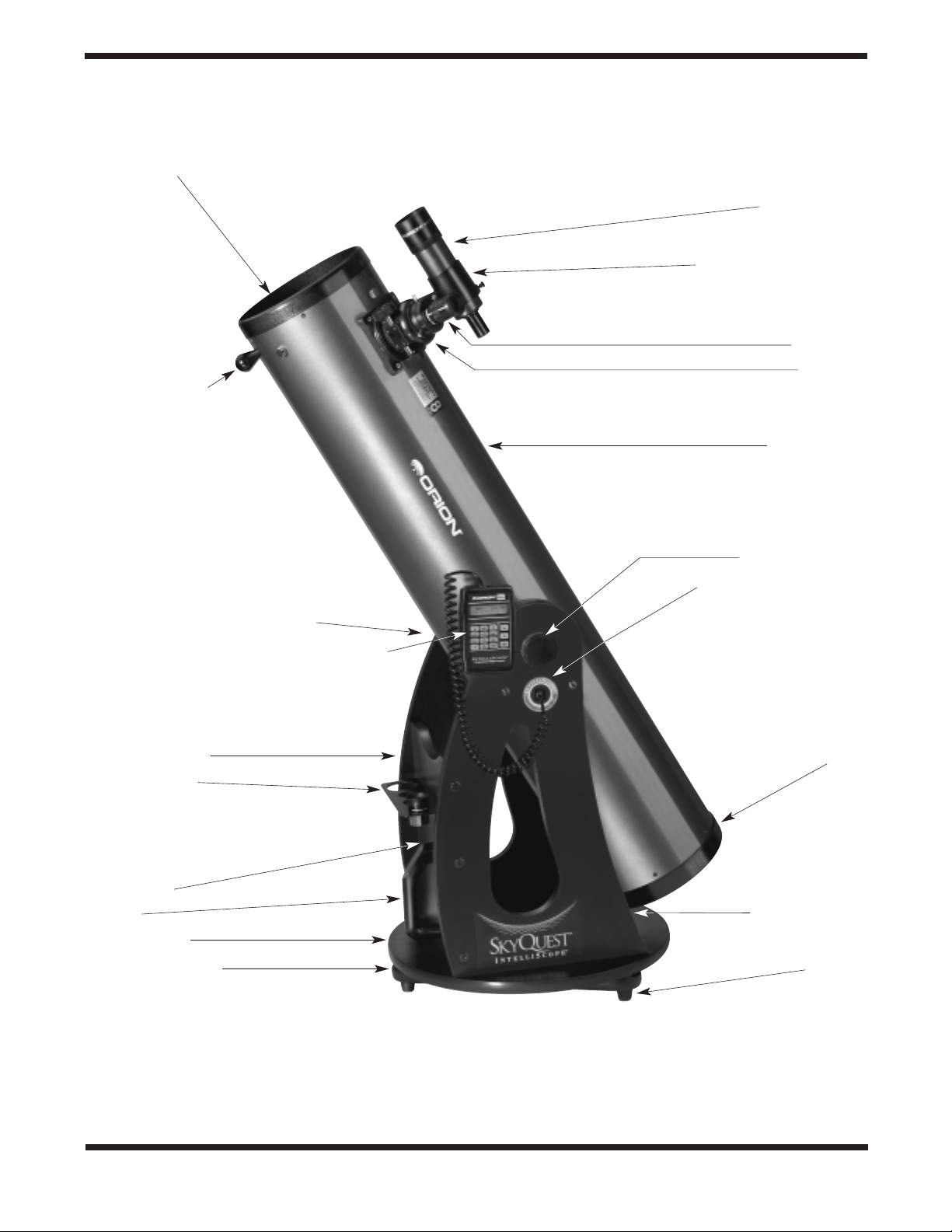
Figure 1. The SkyQuest XT8 IntelliScope
Secondary mirror holder with 4-vane spider
(not visible)
Finder scope
Finder scope bracket
Eyepiece
Focuser
Optical tube
Tensioning knob
IntelliScope Controller
Port modular jack
Primary mirror cell
Left side panel
Foot (3)
Navigation knob
Retaining knob (opposite side)
Computerized Object Locator (optional)
Right side panel
Eyepiece rack
Front brace
Handle
Top baseplate
Ground baseplate

3
Congratulations on your purchase of an Orion SkyQuest XT IntelliScope Dobsonian. It is a high-performance astronomical instrument designed to provide dazzling views of celestial objects and
unprecedented ease of use.With the addition of the optional IntelliScope Computerized Object Locator
(Controller), you gain the ability to locate and view thousands of celestial objects with the push of a button.Searching for objects is a thing of the past, as the IntelliScope’ s high-resolution digital encoders find
them for you — in seconds. It’s so easy!
Even if you decide not to purchase the optional IntelliScope Controller, your SkyQuest telescope will provide years of stargazing enjoyment, thanks to its large-aperture, precision optics; its innovative,
user-friendly design; and its complement of outstanding features and accessories.We hope you enjoy
your journey through the universe!
Please read these instructions thoroughly before beginning assembly and subsequent use of the telescope.
Table of Contents
1. Unpacking . . . . . . . . . . . . . . . . . . . . . . . .3
2. Assembly . . . . . . . . . . . . . . . . . . . . . . . . .4
3. Using Your Telescope . . . . . . . . . . . . . . .8
4. Alignment (Collimation) of the
Optical System . . . . . . . . . . . . . . . . . . .12
5. Astronomical Observing . . . . . . . . . . . .15
6. Optional IntelliScope Computerized
Object Location . . . . . . . . . . . . . . . . . . .17
7. Care and Maintenance . . . . . . . . . . . . .18
8. Specifications . . . . . . . . . . . . . . . . . . . .19
1. Unpacking
The telescope is packed in two bo xes, one containing the optical tube assembly and accessories, the other containing the
unassembled Dobsonian base. Be careful unpacking the
boxes.We recommend keeping the original shipping containers. In the event that the telescope needs to be shipped to
another location, or returned to Orion for warranty repair, having the proper shipping containers will help ensure that your
telescope will survive the journey intact.
Make sure all the parts in the Parts List below are present. Be
sure to check boxes carefully, as some parts are small. If anything appears to be missing or broken, immediately call Orion
Customer Support (800-676-1343) or email sales@telescope.com for assistance.
Parts List
Box #1: Optical Tube Assembly and Accessories
Qty. Description
1 Optical tube assembly
1 Dust cover
1 25mm Sirius Plössl eyepiece, 1.25" barrel diameter
1 10mm Sirius Plössl eyepiece, 1.25" barrel diameter
1 9x50 finder scope (6x30 for the XT6)
1 Finder scope bracket with O-ring
1 Collimation cap
1 4-Hole eyepiece rack (3 hole for XT6)
2 Eyepiece rack mounting wood screws (length 3/4")
2 Tensioning/Retaining knobs
1 Tensioning knob nylon washer (white)
1 Tensioning knob metal washer
1 Nylon retaining knob spacer (black)
1 Handle
2 Handle mounting hex-head screws
2 Handle mounting screw washers
1 Crescent wrench
Box #2: Dobsonian Base
Qty Description
1 Left panel
1 Right panel
1 Front brace
1 Top baseplate
1 Ground baseplate
12 Base assembly wood screws (length 2", black)
3 Teflon azimuth bearing pads (1" diameter)
1 Hex key (size 4mm)
3 Plastic feet
3 Feet attachment wood screws (length 1")
WARNING: Never look directly at the Sun
through your telescope or its finder scope—even
for an instant—without a professionally made
solar filter that completely covers the front of the
instrument, or permanent eye damage could
result.Young children should use this telescope
only with adult supervision.
4
1 Azimuth encoder board
1 Encoder connector board
5 Encoder board mounting wood screws
1 Brass bushing
1 Encoder disk
1 Azimuth axis hex-head screw (length 2.25")
2 Fender washers (diameter 1")
1 Hex lock nut
4 Altitude bearing cylinders
4 Altitude bearing cylinder screws (length 1-3/4",
black)
1 Vertical stop knob
1 Nylon spacer (white)
3 Flat washers (2x
1
/16" thick, 1x1/32" thick)
(Please note: Unless otherwise specified, all images and pictures in this manual are of the SkyQuest XT8.)
2. Assembly
Now that you hav e unpac k ed the bo xes and familiarized yourself with all the parts in front of you, it’s time to begin
assembly.The optics of the telescope are already installed in
the tube, so most of the required assembly concerns the
Dobsonian base.
Assembly of the Dobsonian Base
Refer to Figure 2 during base assembly. The base need only
be assembled once, unless you disassemble it for long-term
storage.The assembly process takes about 30 minutes and
requires, in addition to the supplied tools, a Phillips screwdriver, and two adjustable crescent wrenches.You can substitute
a 7/16" crescent wrench for one of the adjustable crescent
wrenches, or use a pair of pliers.
The azimuth encoder board and other encoder items should
be installed, even if you do not plan to use the optional
Computerized Object Locator.The smooth motion of the telescope depends on the installation of these parts.
When tightening screws, tighten them until firm, but be careful not to strip the holes by over-tightening. If you use an
electric screwdriver, do final tightening with a standard scre wdriver to avoid stripping.
1. With a Phillips screwdriver, screw the plastic feet into the
underside of the ground baseplate (A) using the self-tapping wood screws provided.Insert the screws through the
feet and thread them into the predrilled starter holes.
2. Loosely attach the front brace (B) to the two side panels
(C) with six of the base assembly screws in the predrilled
holes.Use the 4mm hex wrench to tighten the screws.The
side panels should be oriented so the SkyQuest
IntelliScope labels are facing outward.Do not completely
tighten the screws yet.
3. Connect the two side panels (C) with the front brace
attached to the top baseplate (D) with the remaining six
base assembly screws in the predrilled holes.The side of
the baseplate with the pilot hole near the square-shaped
cutout should be facing downwards.Tighten all six screws
firmly .
4. Tighten the six side screws installed earlier.
5. Attach the azimuth encoder board (E) to the underside of
the top baseplate (D) (Figure 3). Insert the modular jack
on the encoder board into the square-shaped hole in the
baseplate and align the encoder board so that the small
slotted hole in the board lines up with the predrilled starter
hole, and the large hole lines up with the central hole in
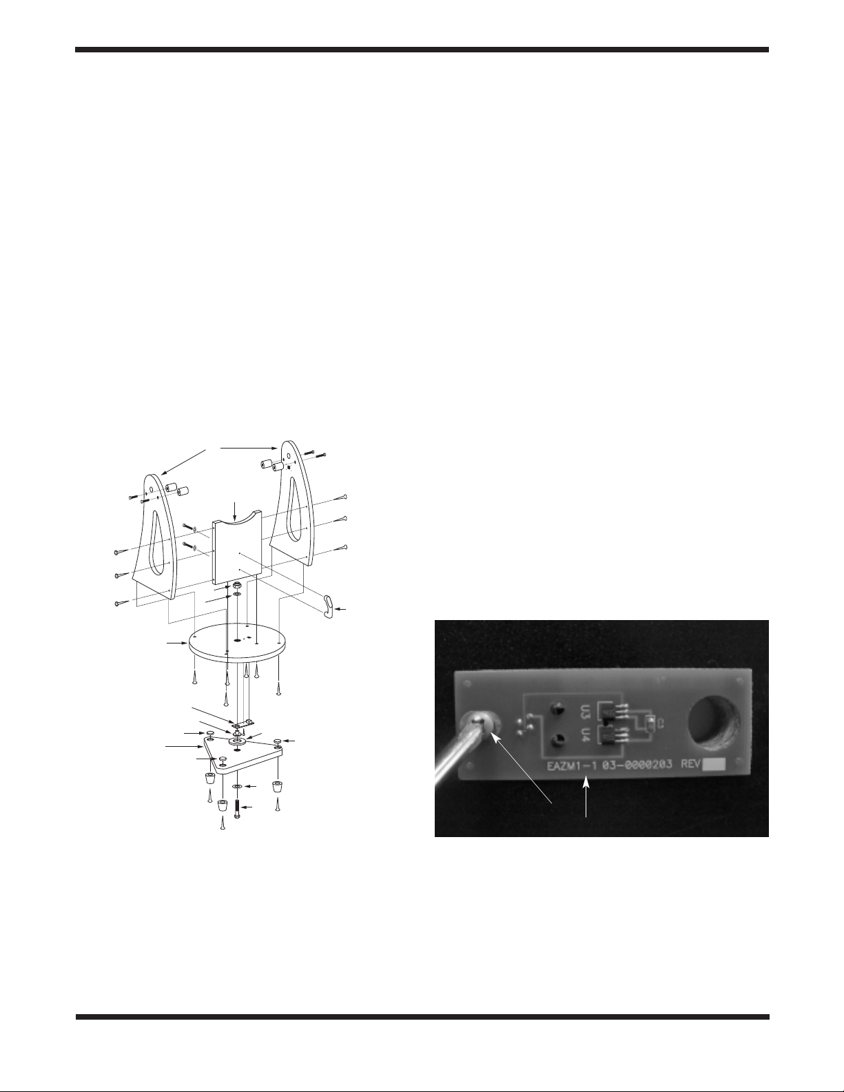
Figure 2. Exploded view of the Dobsonian base.
Figure 3. Installing the azimuth encoder board.Line up the large
hole in the encoder board with the central hole in the top baseplate.
Encoder board
mounting screw
Azimuth encoder board
C
B
L
K
M
D
E
F
G
A
J
G
G
H
I
5
the baseplate.Thread an encoder board mounting screw
into the predrilled starter hole with a Phillips screwdriver
and tighten until just tight.
6. Place one Teflon bearing pad (G) into each recessed hole
on the ground baseplate (A).The bearing pads will be loose
in the recessed hole and should remain that way. Do not
attempt to permanently secure the bearing pads by any
means as this will interfere with the motion of the telescope.
7. Place one fender washer (H) onto the azimuth axis screw
(I).Then push the screw up through the hole in the ground
baseplate (A).Then slide the encoder disk (J), flat side
down, onto the azimuth axis screw.
8.Place the brass bushing (F) onto the azimuth axis screw (I)
so that the wide end of the bushing is closest to the
encoder disk (J). Seat the bushing onto the encoder disk
so that the registration feature on the bushing goes into
the hole in the encoder disk.You may need to move the
encoder disk around on the azimuth axis screw a bit in
order for the bushing to seat properly.
9. Carefully position the top baseplate (D) over the ground
baseplate (A) and lower it so the brass bushing (F) goes
into in the center hole of the top baseplate. Place the
remaining fender washer (K) onto the shaft of the azimuth
axis screw, then thread the hex lock nut (L) onto the end
of the azimuth axis screw and tighten it finger tight, for
now.
10. To tighten the azimuth axis screw (I) and hex lock nut (L),
tilt the assembled Dobsonian base at a slight angle to lift
the ground baseplate off the ground.Do not turn the base
on its side, as this will cause the Teflon bearing pads to fall
out. Now, with one wrench (or pliers) hold the head of the
azimuth axis screw still while turning the hex lock nut with
the other wrench.Figure 4 shows this being done.Tighten
the hex lock nut just until the top fender washer is no
longer moving freely, then tighten the hex nut a 3/16-1/4
turn beyond that. This ensures proper spacing between
the encoder disk and the azimuth encoder board.
11.Attach the handle (M) to the front brace (B) with the two
handle mounting hex-head screws.Place one washer on
each screw, then press the handle against the front brace
(the end of the handle with the logo should be up).Then
thread the screws from the inside of the base into the handle until tight using the supplied crescent wrench.
12.Line up one of the altitude bearing cylinders with the
inside of one of the four bearing cylinder holes on the side
panels. Push a bearing cylinder screw through the side
panel and bearing cylinder.Then thread it into the built-in
hex nut on the cylinder with a Phillips head screwdriver
(Figure 5).The beveled end of the cylinder should be facing away from the side panel. Repeat this for the
remaining three bearing cylinders.
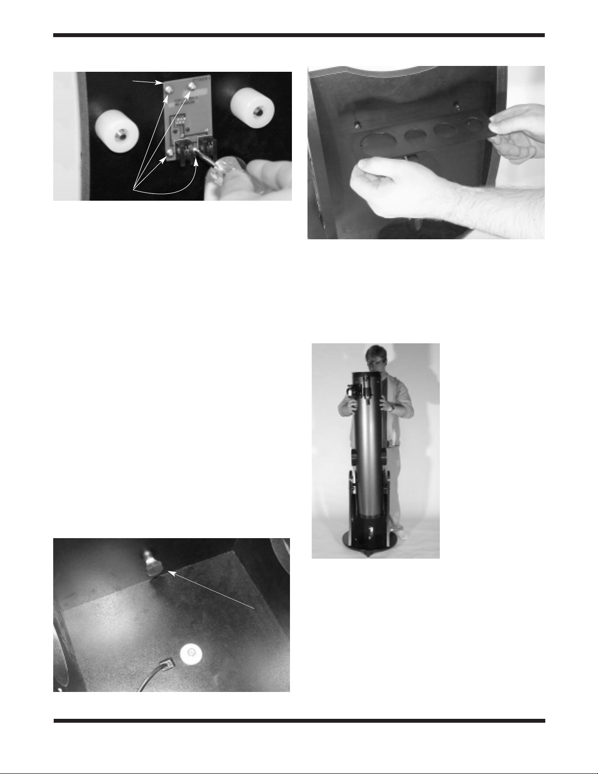
13.Attach the encoder connector board to the side panel.Place
the board against the side panel so that the modular jack fits
into the square-shaped hole and thread four encoder board
mounting screws through the connector board and into the
predrilled holes in the side panel until tight (Figure 6).
There are some predrilled holes on the side panel opposite
the panel that holds the encoder connector board. These
holes will be used to mount parts that come with the optional
IntelliScope controller.If you purchased the IntelliScope controller with your SkyQuest, you will want to follow the
installation instructions in the controller’s manual at this time.
Installing the Vertical Stop
Place the nylon spacer (white) and the three flat washers
onto the shaft of the vertical stop screw.Thread the vertical
stop into the threaded hole on the inside of front panel until
tight (Figure 7).The position of the ver tical stop is adjustable
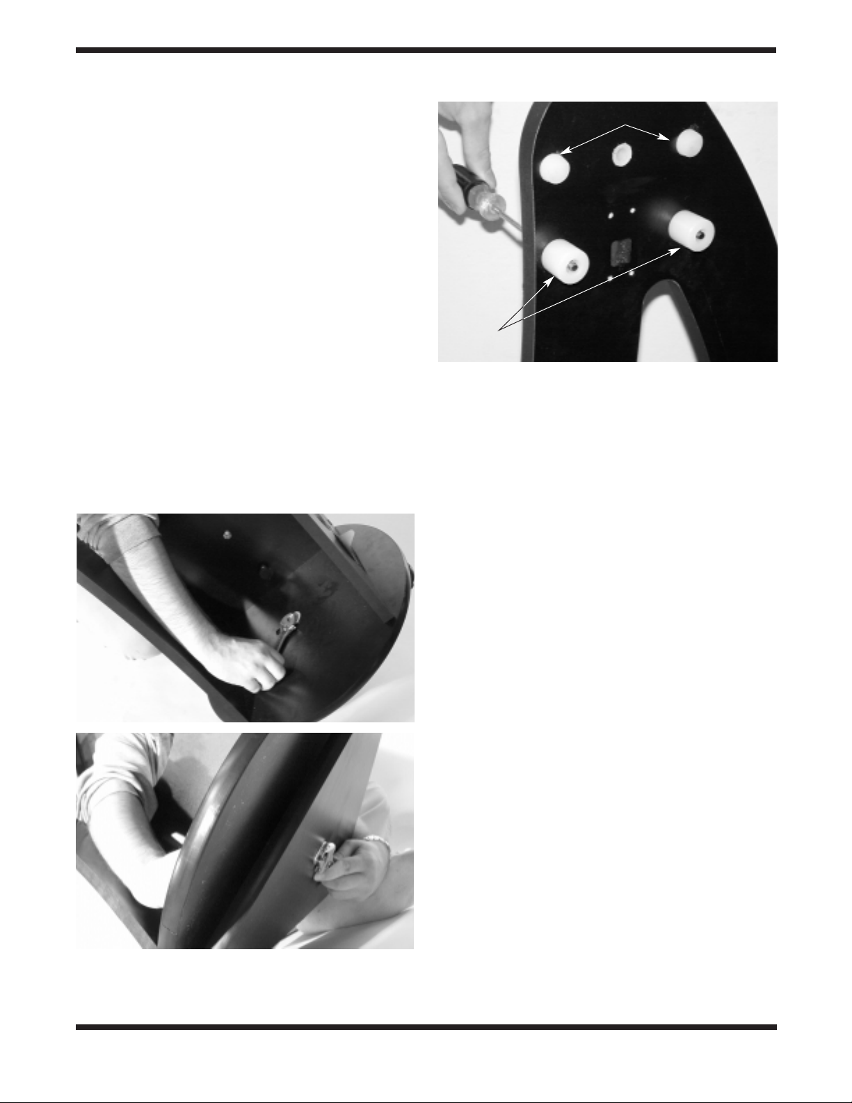
Figure 4. To connect the baseplates, tilt them only slightly, as shown.
Do not place them on their side.(a) Use one wrench to hold the hex
nut steady (b) while turning the other end of the azimuth axis screw.
Figure 5. Attaching the bearing cylinders. (XT10 Shown)
b.
a.
Correct Tension pads
Bearing
cylinders
by adding or removing washers.This is important when using
the optional IntelliScope Computerized Object Locator, since
the optical tube must be exactly vertical during the two-star
alignment procedure.
Installing the Eyepiece Rack
The aluminum eyepiece rack is a standard accessory on
SkyQuest IntelliScope Dobsonians. It holds three 1.25" eyepieces and one 2" eyepiece (three 1.25" eyepieces on the
XT6) in a convenient place on the base, within easy reach
while you’re observing.A 1.25" barlow lens also can be held
in the rack.A few inches down from the top of the front brace
panel you will notice two predrilled starter holes, about 6"
apart. Thread the black wood screws into the starter holes
with a Phillips screwdriver. Then you can “keyhole” the eyepiece rack onto the wood screws and continue tightening the
screws (Figure 8). If you want to be able to remove the rack,
do not tighten the screws too tightly. Be certain that the
screws are loose enough that you can lift the rack and remo ve
it from the screws through the larger part of the keyhole.If you
want to have the rack permanently attached, tighten the
screws.You may find it easier to carry the base by the handle
if the eyepiece rack is removed.
Placing the Optical Tube on the Dobsonian Base
Lift the optical tube and gently place it into the Dobsonian
base so that the altitude bearings on either side of the tube
rest on the bearing cylinders.Orient the optical tube as shown
in Figure 9. Make certain that the optical tube does not get
hung up on the vertical bumper stop or the CorrecTension
pads as you put it in place.Be careful when placing the tube
on the bearings, since if it is inserted at the wrong angle the
hub can strike the encoder connector board and potentially
damage it. Once on the bear ing cylinders, the tube should
pivot freely up and down with gentle hand pressure.Note that
the tube will not yet be properly balanced, since the eyepiece
and finder scope are not in place, and the CorrecTension system has not been installed.
Installing the CorrecTension Friction
Optimization System
An exciting feature of the SkyQuest IntelliScope Dobsonian is
the redesigned CorrecTension (XT) system. Because of their
relatively light weight, smaller Dobsonians (under 16") have
always been plagued by insufficient friction on the altitude
bearing surfaces. As a result, such telescopes move up and
6
Figure 8. Using the two supplied screws, install the aluminum
eyepiece rack in the predrilled holes near the top of the front
baseplate.
Figure 6. Attaching the encoder connector board. (XT10 Shown)
Figure 7. The vertical stop
Ver tical Stop
Figure 9. Lift the optical
tube and place it into the
Dobsonian base so that the
altitude bearings rest on the
bearing cylinders. Orient the
optical tube as shown. Do
not bump the encoder
connector board or vertical
stop when installing the
optical tube.
Encoder
connector
board
Screws