

Page 1
System Manager TS II
In-House Technical Guide
VCB-X Controller Code: SS1051 Version 2.0 and up
VCM-X Controller: SS1026 & Y200920 Version 2.0 and up;
VCM-X Modular Controller: Tulsa - SS1030; Coil - SS1034
VCM-X WSHP Controller: Tulsa - SS1032; Coil - SS1033
VAV/Zone Controller: SS1001, SS1005, SS1025
VCM Controller: SS1016
Page 2

Table of Contents
OVERVIEW ........................................................................................................................................................ 4
COMPONENTS AND WIRING ............................................................................................................................ 5
Flush Wall Mount Dimensions and Components .........................................................................................................................6
Surface Mount Components and Dimensions ..............................................................................................................................7
SMTS II to VCM Controller Wiring ................................................................................................................................................8
SMTS II to VCM-X Controller Wiring ............................................................................................................................................9
SMTS II to VCB-X Controller Wiring...........................................................................................................................................10
SMTS II to VAV/Zone Controller Actuator Package Wiring ........................................................................................................11
NAVIGATION .................................................................................................................................................. 12
Main Screen Icons and Button Functions...................................................................................................................................12
MAIN SCREEN FUNCTIONS ........................................................................................................................... 14
Logging In...................................................................................................................................................................................14
Editing Passcodes ......................................................................................................................................................................15
Setting The System Clock ..........................................................................................................................................................16
System Manager Settings ..........................................................................................................................................................17
Alarm Polling ..............................................................................................................................................................................18
Unit Selection .............................................................................................................................................................................19
VCM, VCM-X & VCB-X CONTROLLERS........................................................................................................... 19
Viewing Status Screens .............................................................................................................................................................19
Viewing & Enabling/Disabling VCM & VCM-X Alarms ................................................................................................................21
Viewing & Enabling/Disabling VCB-X Alarms ............................................................................................................................22
Viewing and Setting Schedules .................................................................................................................................................23
Viewing and Setting and Holidays ..............................................................................................................................................24
Forcing Schedules......................................................................................................................................................................24
VCM & VCM-X CONTROLLERS ....................................................................................................................... 25
Accessing and Entering VCM / VCM-X Setpoints ......................................................................................................................25
VCM / VCM-X Confi guration Setpoints ......................................................................................................................................26
VCM / VCM-X Temperature Setpoints ........................................................................................................................................32
VCM / VCM-X Static Setpoints ...................................................................................................................................................35
VCM / VCM-X Staging Delays Setpoints....................................................................................................................................37
VCM / VCM-X Miscellaneous Setpoints .....................................................................................................................................38
VCM / VCM-X Calibration Setpoints...........................................................................................................................................40
VCM / VCM-X Relay Outputs Setpoints .....................................................................................................................................41
VCB-X CONTROLLERS ................................................................................................................................... 42
Accessing and Entering VCB-X Setpoints..................................................................................................................................42
VCB-X Confi guration Setpoints ..................................................................................................................................................43
VCB-X Temperature Setpoints ................................................................................................... ................................................50
VCB-X Static Setpoints ..............................................................................................................................................................54
VCB-X Staging Delays Setpoints ...............................................................................................................................................56
VCB-X Miscellaneous Setpoints.................................................................................................................................................59
VCB-X Relay Outputs Setpoints.................................................................................................................................................62
www.orioncontrols.com
WattMaster Controls Inc.
8500 NW River Park Drive · Parkville , MO 64152
Toll Free Phone: 866-918-1100
PH: (816) 505-1100 · FAX: (816) 505-1101 ·
E-mail: mail@wattmaster.com
Visit our web site at www.orioncontrols.com
Form: OR-SMTSII-In-House-TGD-01E
Copyright April 2015 WattMaster Controls, Inc.
AAON® is a registered trademark of AAON, Inc., Tulsa, OK.
WattMaster Controls, Inc. assumes no responsibility for errors or
omissions.
This document is subject to change without notice.
Page 3

Table of Contents
VAV/ZONE CONTROLLERS ............................................................................................................................. 63
Viewing VAV/Box Status Screens...............................................................................................................................................63
Viewing Alarm Status .................................................................................................................................................................63
Enabling/Disabling VAV/Zone Alarms ........................................................................................................................................63
Accessing and Entering VAV/Zone Setpoints .............................................................................................................................64
VAV/Zone Confi guration Setpoints .............................................................................................................................................65
V AV/Zone Temperature Setpoints ................................................................................................ ..............................................66
VAV/Zone Damper/Airfl ow Setpoints ................................................................................................................. .........................67
V A V/Zone Alarm Settings ...........................................................................................................................................................68
VAV/Zone Miscellaneous Setpoints ............................................................................................................................................69
VAV/Zone Calibration Setpoints .................................................................................................................................................69
APPENDIX ...................................................................................................................................................... 70
Troubleshooting - System Manager TS II LEDs, Buttons, Dipswitches & Jumpers ...................................................................70
System Confi guration .................................................................................................................................................................71
Alarm Polling Setup Using Prism 2 ............................................................................................................................................75
Military Time Conversion ............................................................................................................................................................76
INDEX ............................................................................................................................................................. 77
Page 4
Overview
System Manager TS II
Zone
Zone
Features
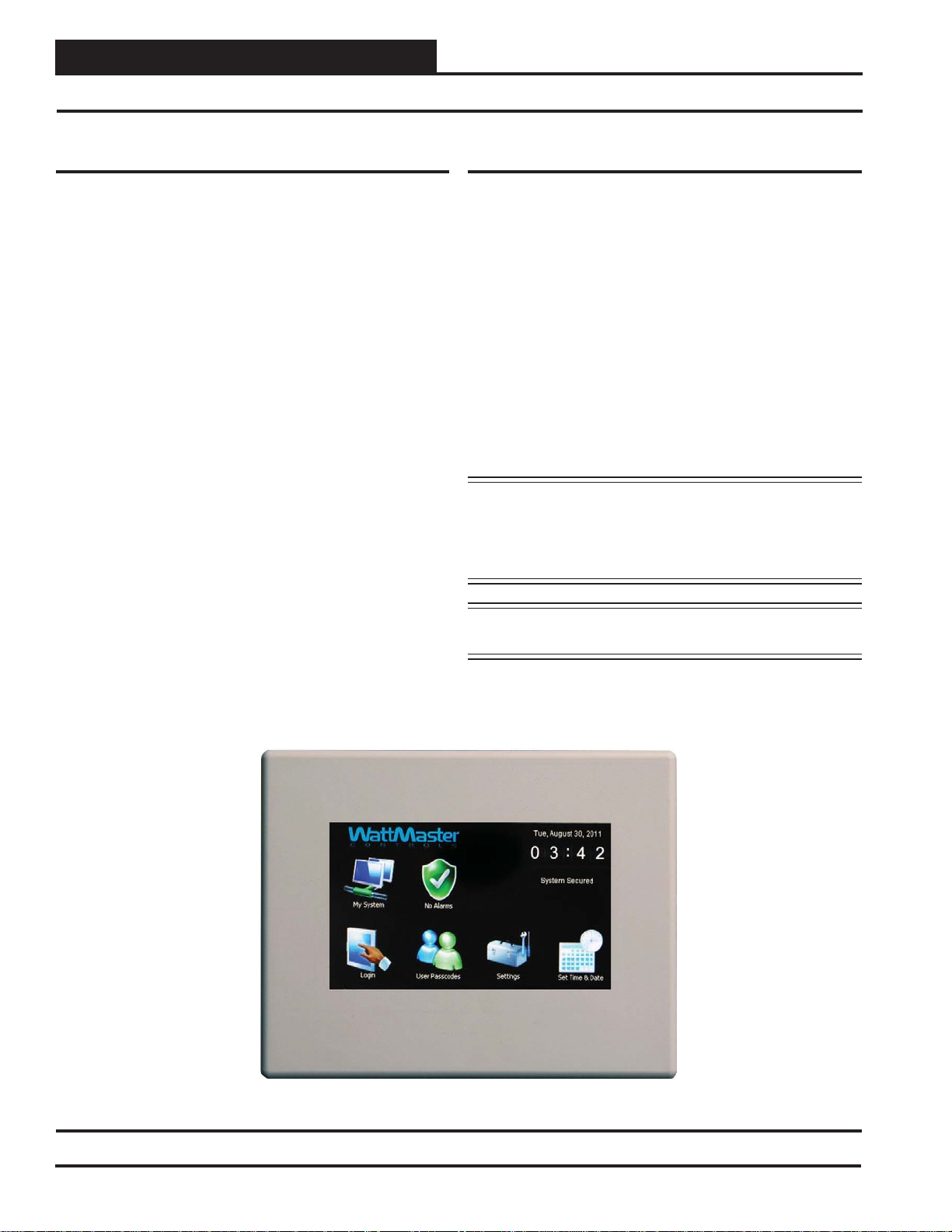
The OE392-10 System Manager TS II (Touch Screen) provides a direct,
graphic-enhanced, menu-driven link to enable you to view the status and
adjust the setpoints of most controllers on the Orion Controls System.
(See Figure 1.)
The System Manager TS II provides the following useful functions:
• Provides a 4.3” 480 x 272 WQVGA RGB TFT LCD Graphical
Touch Screen LCD display with 16 million colors
• Utilizes a graphical touch screen menu system with easyto-understand menu trees and icons and non-cryptic, plain
English language messages
• Makes entering data quick and easy with instructions on each
confi guration and setpoint screen
• Graphic programming and status screens provide easy setup
and operation without the need for specialized training
• Provides protection from unauthorized users through integral
multi-level passcode authorization programming
• Comes equipped with real-time clock backup power supply
for short power losses
• Provides icons to indicate alarm conditions
System Requirements
• The System Manager TS II is packaged and assembled as fl ush
wall mount. Surface mount components are also included for
your convenience.
• If using the surface mount version, you will need a double
duplex outlet box (by others).
• The System Manager TS II only works with the following
VAV/Zone Controller EPROMs: SS1001, SS1005, SS1025
• The System Manager TS II only works with the following
VCM, VCM-X, VCM-X Modular, VCM-X WSHP, and
VCB-X Controller EPROMs: All standard SS1016, SS1026,
SS1030, SS1032, SS1033, SS1034, SS1051 and later
*• USB-Link, CommLink, or MiniLink Polling Device
*NOTE: Alarm polling must fi rst be set up in Prism 2. This requires a
personal computer with Prism 2 software and a USB-Link or
CommLink and a MiniLink Polling Device. Ongoing alarm
polling on the System Manager TS II Main Scr een requires
a MiniLink to be connected to the system.
• LEDs behind plastic panel indicate power, communications,
and operation
• Plastic enclosure allows for easy fl ush wall mounting in
hollow drywall or surface mounting on solid wall surface
NOTE: Screens in this manual referring to VCM-X also apply
to VCM controllers.
Figure 1: System Manager TS II
4
Revised 4/25/14
SMTS Technical Guide
Page 5
Components and Wiring
Mounting, Wiring, Initializing, and Updating
Environmental Requirements
The System Manager TS II needs to be installed in an environment that
can maintain a temperature range between 14°F and 158°F with less
than 90% RH levels (non-condensing).
Mounting
The System Manager TS II is housed in a plastic enclosure designed
for mounting in hollow drywall construction or a control panel cover
with the fl ush wall mount version (shown in Figure 3) or on a concrete,
brick, or other solid wall surface with the surface mount version (shown
in Figure 4).
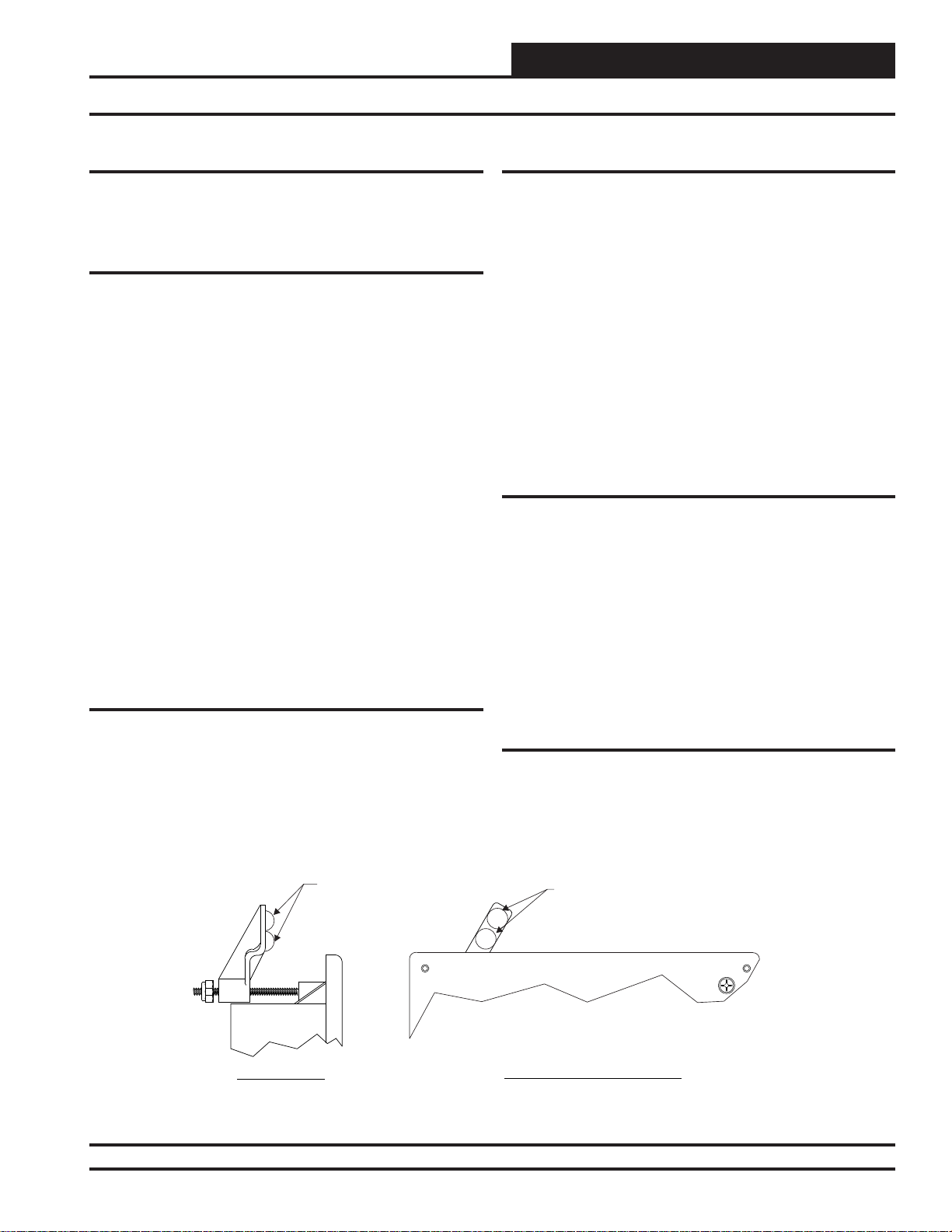
The fl ush wall mount version has integral wingnut paddles that are tight-
ened after installation to grip the drywall and hold the System Manager
TS II in place. For mounting in a control panel cover or other thin material, (4) adhesive backed rubber pads are provided to assist in securing
the System Manager TS II into the cutout in the panel. These pads are
applied to the wingnut paddles to provide a non-slip mounting against
the panel’s sheet metal surface. See Figur e 2 for pad placement details.
The surface mount version is designed to be installed in a double duplex
outlet box (by others). Both mounting styles of the System Manager
TS II feature an integral, magnetically-secured face plate which can be
easily removed for reset of the display when required.
The System Manager TS II should be mounted at approximately eye
level to allow for ease of programming and reading of the display. The
System Manager TS II is typically mounted in the building manager’s
or superintendent’s offi ce or in an equipment room, but is also quite
suitable for mounting in any location or with most decors.
Care
Wiring
The System Manager TS II is connected to the local communications
loop of the Orion system via 18 AWG 2-conductor, twisted pair with
shield wire connected to the T , SHLD & R communication terminals on
the back of the System Manager TS II. The communications wire used
can be either our WattMaster # WR-LL-WG-18 communications wire
or Belden #82760 wire or its equivalent.
The System Manager TS II also requires that 24 VAC (6 VA) power be
supplied (by others) to its + and – wiring terminal located on the back
of the System Manager TS II.
See Figur es 5-8 for wiring details. These wiring diagrams depict wiring
the System Manager TS II to the VCM-X Controller , VCM Controller,
VCB-X Controller and VAV/Zone Controller. The System Manager TS II
can also be wired to the local loop terminals on the MiniLink PD, Power
Comm Board, or any other add-on controller’s local loop terminals. It
will still require a transformer to be wired as shown in Figures 5, 6 & 7.
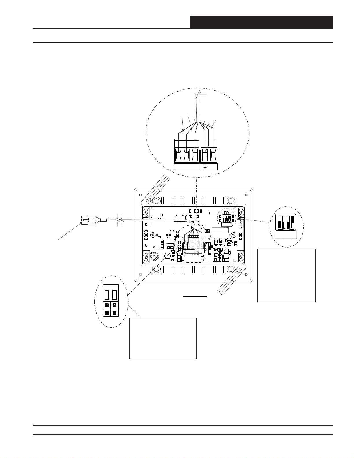
Dipswitch and Jumper Settings
If you are using a VCB-X Controller set at high speed, Dipswitch OPT1
should be set to ON; in all other instances, it should be set to OFF . As of
April 2014, Dipswitch OPT4 should be set to ON by default. Previous
versions should be set to OFF. If you see your screen is not centered
correctly, switch OPT4 to the opposite position. Dipswitches OPT2
and OPT3 should always be set to OFF. See Figures 5-8, pages 8-11
for details.
If you have a Stand-Alone system (no CommLink or MiniLink, the
TERM Jumpers must be ON. For applications with CommLink(s) and/
or MiniLink(s), the TERM Jumpers must be OFF. See Figures 5-8,
pages 8-11 for details.
The System Manager TS II should be cleaned with a soft, dust-free cloth.
Do not use any liquid to clean your System Manager TS II. You should
press the < Suspend> button located behind the cover to temporarily
freeze the touch pad before you attempt to clean your screen. See the
Troubleshooting section on page 70 for details.
Rubber Pads
USE 4
Left Side View
Technical Support
Call (866) 918-1100 to talk to a WattMaster Controls T echnical Support
Representative. Support is available Monday through Friday, 7:00 AM
to 5:00 PM central standard time.
Place (2) On Each Paddle Arm
As Shown When Mounting In Sheet Metal
Panel Or Other Thin Mounting Material. Pads
Are Not Required For Drywall Mounting
Front View (Cover Removed)
Rubber Pads
Figure 2: System Manager TS II - Control Panel Mounting Pad Placement Detail ( Flush Wall Mount)
SMTS II Technical Guide
Revised 4/21/14
5
Page 6
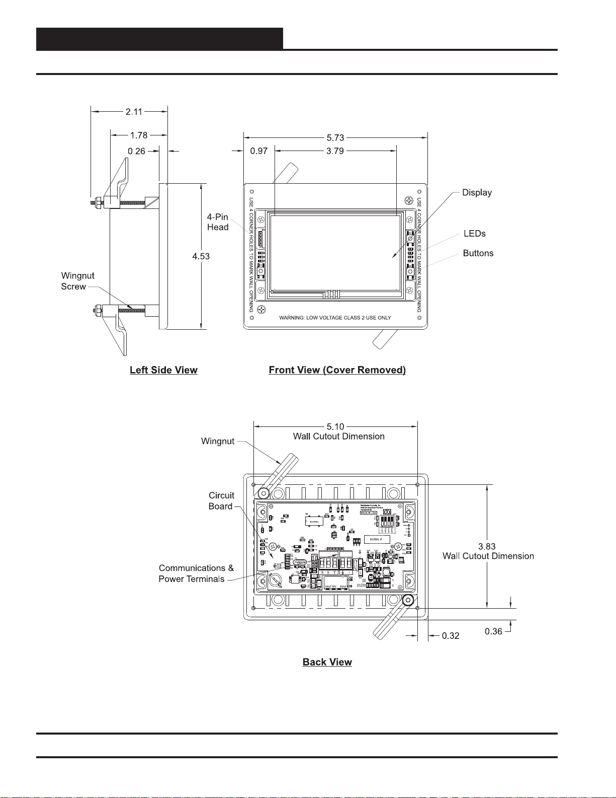
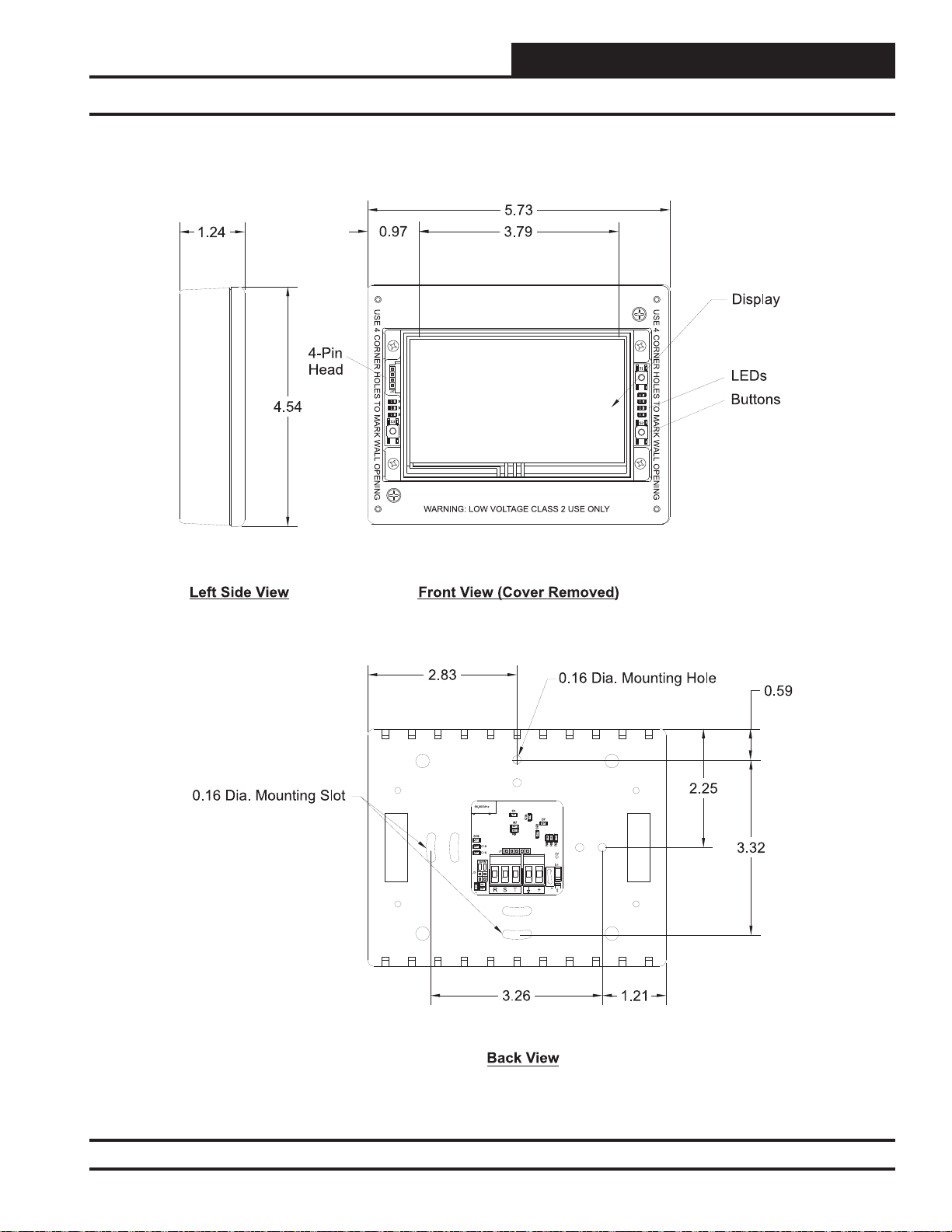
Components and Wiring
Wall Mount Dimensions and Components
Figure 3: System Manager TS II Dimensions and Components ( Flush Wall Mount)
6
SMTS II Technical Guide
Page 7
Components and Wiring
Surface Mount Components and Dimensions
Figure 4: System Manager TS II Dimensions and Components ( Surface Mount)
SMTS II Technical Guide
7
Page 8
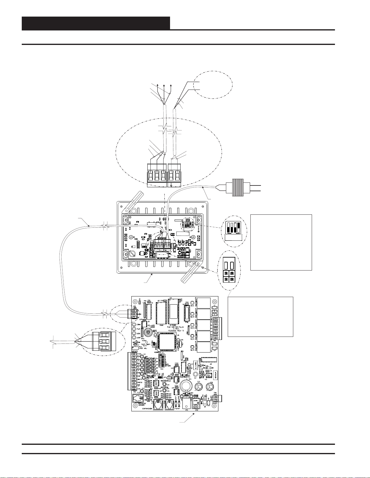
Components and Wiring
SMTS II to VCM Controller Wiring
On VCM
On VCM
To T Terminal
To S Terminal
T
C13
C11
C10
C9
C13
C11
C10
C9
.1uF
.1uF
.1uF
.1uF
X3
X3
C14
C14
.1uF
.1uF
R1
R1
1002
C12
C12
66.000Mhz
C1
C1
.1uF
.1uF
C15
C15
R7
R7
1002
1002
R9
R9
C19
C19
.1uF
.1uF
C18
J1
.1uF
.1uF
C16
C17
TERM
8.00Mhz
J3
R46
R43
1002
R47
1002
1002
RRSST
+
1002
D12
1002
R49
1002
R44
R48
1002
R45
330uF 50V 330uF
C24
C24
Run 2 Conductor
Twisted Pair W/Shield
Cable. WattMaster
WR-LL-WG-18 Cable
Or Equivalent From
System Manager To
VCM Controller
BLACK (R)
BARE (S)
WHITE (T)
WHITE (T)
BARE (S)
BLACK (R)
.1uF
.1uF
.1uF
C23
R20
C26
1002
C25
R10
.1uF
1002
R22
1002
R24
1002
R27
R36
1002
1002
1002
R29
R12
R14
1002
RTC
CAL
C39
C39
C20
C20
.1uF
C6
C8
.1uF
R17
1002
R26
1002
X2
C45
.1uF
1002
1002
R40
.1uF
.1uF
1002
R42
C5 C4
C50
C51
C51
L5
.1uF
1002
R37
C7
C7
.1uF
1002
1002
R6R5R2
R6R5R2
V1
On VCM
To R Terminal
+
WattMaster Controls, Inc
WattMaster Controls, Inc
WQVGAGraphical Interface
WQVGAGraphical Interface
YS102178 R4
YS102178 R4
MADE IN USA
1002
5V 3.3V 2.5V
D1
U10
.1uF
C27
.1uF
C28
1002
R11
R33
1002
R25
C31
R19U9R28
C32 R30
BROWN (GND)
RED (24 VAC)
BROWN (GND)
RED (24 VAC)
SW1
R13R8
1002 1002
1002 1002
R34 R16
GND
OFF
OPT4
OPT3
OPT2
OPT1
5V
SERIAL#
R21
R23
R35
1002
C36
C34 C40
R39
D11
.1uF
U13
.1uF
.1uF
.1uF
C41
1002
R32R31
1002
1002
L4
1002
R41
U11
R15
Q2
L1
C29
R18
1002
.1uF
.1uF
.1uF
C30
D2
C35
LTC3824
C2C3
1002
1002
.1uF
.1uF
1002
1002 1002
To (24 VAC)
Transformer -
To (24 VAC)
Transformer +
24 VAC Transformer
5 VA Minimum
Line Voltage
Run 2 Conductor 20 Ga. Minimum Cable From
System Manager TS Terminals To 24 VAC
NOTE: Dip Switches OPT1,
R
T
1002
1002
1002
OFF
OPT2
OPT1
OPT2 & OPT3.Should Be
Set To Off As Of April 2014,
OPT4 Should Be Set To ON
OPT4
OPT3
By Default. Previous Versions
Should Be Set To OFF. If You
See Your Screen Is Not
TERM
Centered Correctly, Switch
OPT4 To The Opposite
Position.
System Manager TS
Back View
WHITE (T)
BARE (S)
BLACK (R)
T
S
R
VCM Controller
Front View
Figure 5: System Manager TS II to VCM Controller Wiring
NOTE: For Stand-Alone
Installations (No CommLink
or MiniLink), Both TERM
Jumpers Must Be ON.
For All Applications With
CommLink(s) Or MiniLink(s),
Both Jumpers Must Be OFF.
8
Revised 4/21/14
SMTS II Technical Guide
Page 9
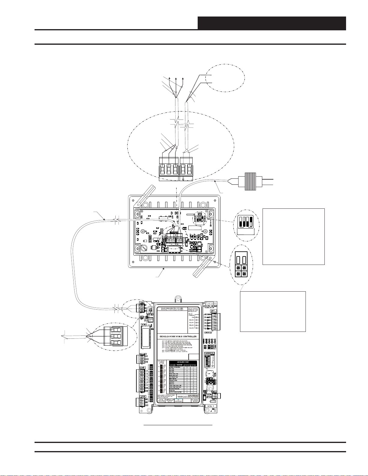
Components and Wiring
SMTS II to VCM-X Controller Wiring
Run 2 Conductor
Twisted Pair W/Shield
Cable. WattMaster
WR-LL-WG-18 Cable
Or Equivalent From
System Manager To
VCM-X Controller
BLACK (R)
BARE (S)
WHITE (T)
WHITE (T)
BARE (S)
BLACK (R)
.1uF
.1uF
.1uF
C23
R20
C26
1002
C25
R10
.1uF
1002
R22
1002
R24
1002
R27
R36
1002
1002
1002
R29
1002
1002
R12
.1uF
1002
R14
1002
RTC
1002
CAL
1002
C39
C39
On VCM-X
To T Terminal
To S Terminal
On VCM-X
On VCM-X
To R Terminal
To (24 VAC)
Transformer -
To (24 VAC)
Transformer +
BROWN (GND)
RED (24 VAC)
BROWN (GND)
RED (24 VAC)
24 VAC Transformer
5 VA Minimum
T
+
Line Voltage
Run 2 Conductor 20 Ga. Minimum Cable From
System Manager TS Terminals To 24 VAC
WattMaster Controls, Inc
WattMaster Controls, Inc
C13
C11
C10
C9
C13
C11
C10
C9
WQVGAGraphical Interface
WQVGAGraphical Interface
.1uF
.1uF
.1uF
.1uF
YS102178 R4
YS102178 R4
C14
C14
.1uF
R1
R1
1002
C1
C1
.1uF
R7
R7
1002
1002
R9
R9
J1
330uF 50V 330uF
MADE IN USA
1002
1002
5V 3.3V 2.5V
D1
1002
V1
R11
R25
C31
R19U9R28
SW1
R13R8
1002 1002
1002 1002
R34 R16
GND
OFF
R
T
OPT4
OPT3
OPT2
OPT1
5V
SERIAL#
.1uF
U10
.1uF
R15
C27
C29
.1uF
1002
.1uF
C28
LTC3824
R33
.1uF
1002
C32 R30
C34 C40
1002
R21
1002
R35
R23
1002
1002
C36
R39
D11
.1uF
U13
.1uF
.1uF
C41
1002
R32R31
1002
1002
L4
1002
R41
U11
Q2
L1
R18
.1uF
.1uF
C30
D2
C35
C2C3
1002
1002
.1uF
1002
1002 1002
TERM
OFF
OPT2
OPT1
.1uF
C12
C12
.1uF
C15
C15
C7
C7
.1uF
1002
R6R5R2
R6R5R2
+
C24
C24
X3
X3
66.000Mhz
C20
C20
.1uF
C19
C19
.1uF
.1uF
C18
C6
.1uF
.1uF
C16
C8
.1uF
C17
R17
TERM
R26
X2
C45
8.00Mhz
J3
R46
R40
.1uF
.1uF
R43
R42
C5 C4
1002
R47
1002
1002
C50
RRSST
C51
C51
L5
.1uF
1002
D12
R48
1002
1002
R49
1002
1002
R44
R37
R45
NOTE: Dip Switches OPT1,
OPT2 & OPT3.Should Be
Set To Off As Of April 2014,
OPT4 Should Be Set To ON
OPT4
OPT3
By Default. Previous Versions
Should Be Set To OFF. If You
See Your Screen Is Not
Centered Correctly, Switch
OPT4 To The Opposite
Position.
System Manager TS
Back View
WHITE (T)
BARE (S)
BLACK (R)
T
S
R
AI1 SET AI2 SET AI3 SET
AI1
AI2
AI3
AI4
AI5
AI4 SET AI5 SET AI7 SET
AI7
VCM-X Controller - Front View
Figure 6: System Manager TS II to VCM-X Controller Wiring
NOTE: For Stand-Alone
Installations (No CommLink
or MiniLink), Both TERM
Jumpers Must Be ON.
For All Applications With
CommLink(s) Or MiniLink(s),
Both Jumpers Must Be OFF.
SMTS II Technical Guide
Revised 4/21/14
9
Page 10
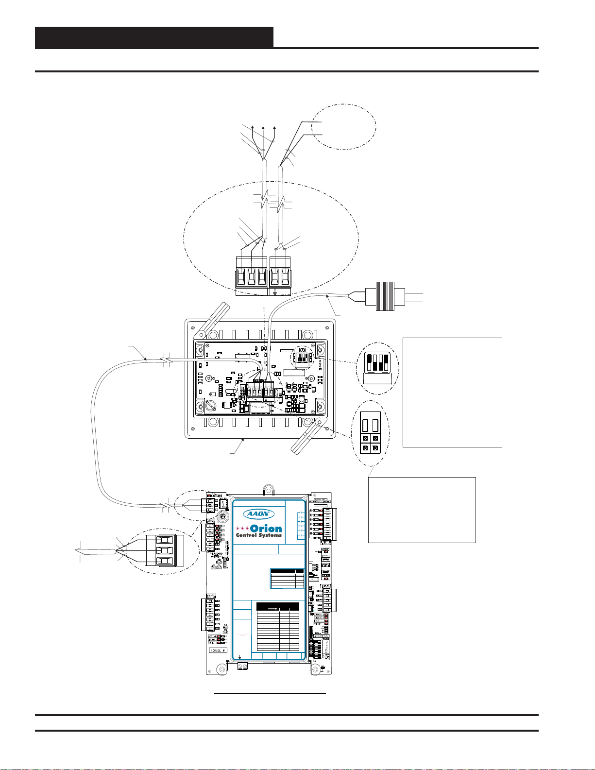
Components and Wiring
SMTS II to VCB-X Controller Wiring
Run 2 Conductor
Twisted Pair W/Shield
Cable. WattMaster
WR-LL-WG-18 Cable
Or Equivalent From
System Manager To
VCB-X Controller
BLACK (R)
BARE (S)
WHITE (T)
WHITE (T)
BARE (S)
BLACK (R)
.1uF
.1uF
R20
C26
1002
C25
R10
.1uF
1002
R22
1002
R24
1002
R27
R36
1002
1002
1002
R29
R12
R14
1002
RTC
CAL
C39
C39
System Manager TS
Back View
On VCB-X
To T Terminal
On VCB-X
To S Terminal
To R Terminal
On VCB-X
To (24 VAC)
Transformer -
To (24 VAC)
Transformer +
BROWN (GND)
RED (24 VAC)
BROWN (GND)
RED (24 VAC)
24 VAC Transformer
5 VA Minimum
T
+
Line Voltage
Run 2 Conductor 20 Ga. Minimum Cable From
System Manager TS Terminals To 24 VAC
WattMaster Controls, Inc
WattMaster Controls, Inc
C13
C11
C10
C9
C13
C11
C10
C9
WQVGAGraphical Interface
WQVGAGraphical Interface
.1uF
.1uF
.1uF
.1uF
YS102178 R4
YS102178 R4
C14
C14
.1uF
R1
R1
1002
C1
C1
.1uF
R7
R7
1002
1002
R9
R9
330uF 50V 330uF
MADE IN USA
1002
1002
5V 3.3V 2.5V
D1
.1uF
C28
1002
V1
R11
R33
R25
C31
R19U9R28
C32 R30
SW1
R13R8
1002 1002
1002 1002
R34 R16
GND
OFF
R
T
OPT4
OPT3
OPT2
OPT1
5V
SERIAL#
C34 C40
.1uF
U10
R15
C27
C29
.1uF
1002
.1uF
LTC3824
.1uF
1002
1002
R21
1002
R35
R23
1002
1002
C36
R39
D11
.1uF
U13
.1uF
.1uF
C41
1002
R32R31
1002
1002
L4
1002
R41
U11
Q2
L1
R18
.1uF
.1uF
C30
D2
C35
C2C3
1002
1002
.1uF
1002
1002 1002
OPT1
TERM
.1uF
C12
C12
.1uF
C15
C15
C7
C7
.1uF
1002
R6R5R2
R6R5R2
+
C24
C24
X3
X3
.1uF
C23
66.000Mhz
C20
C20
.1uF
C19
C19
.1uF
.1uF
C18
C6
J1
.1uF
.1uF
C16
C8
.1uF
C17
R17
1002
TERM
R26
1002
X2
C45
.1uF
8.00Mhz
J3
1002
1002
R46
R40
.1uF
.1uF
R43
1002
R42
C5 C4
1002
R47
1002
1002
C50
RRSST
C51
C51
L5
.1uF
1002
D12
R48
1002
1002
R49
1002
1002
R44
R37
R45
NOTE: Dip Switch OPT1
SW1
Should Be Set To ON When
VCB-X Is Set To High Speed.
OFF
OPT4
OPT3
OPT2
OPT2 & OPT3
Set To Off
. As Of April 2014,
OPT4 Should Be Set To ON
By Default. Previous Versions
Should Be Set To OFF. If You
See Your Screen Is Not
Should Be
Centered Correctly, Switch
OPT4 To The Opposite
Position.
WHITE (T)
BARE (S)
BLACK (R)
RS-485 COMMUNICATION LOOP. WIRE
“R”TO “R”, “T” TO “T” “SHLD” TO “SHLD”
www.aaon.com
T
S
R
www.orioncontrols.com
VCB-X CONTROLLER
Orion No.:OE335-23-VCBX-A
ANALOG INPUTS
AI1= SPC (SPACE TEMPERATURE SENSOR)
AI2
= SAT(SUPPLYAIR TEMPERATURE SENSOR)
AI3
= OAT(OUTDOOR AIR TEMPERATURE SENSOR)
AI4
= DCT(DIGITAL COMP. DISCHARGETEMPERATURE SENSOR)
AI5
= SPACETEMPERATURE SLIDE OFFSET
BINARYINPUTS
BI1
= EMERGENCYSHUTDOWN
BI2
= PROOF OF FLOW
BI3
= DIRTYFILTER
Bi4
= COILTEMPERATURE SWITCH
G OUTPUTS
ANALO
AO1
= FAN VFD
AO2
= ECONOMIZER
AO3
= SCR OR MODULATING HW HEATING
TRIAC OUTPUT
TR1
= DIGITALCOMP. UNLOADER
(24 VAC & UNLOADTERMINALS)
WattMaster Label
#LB102093-01-A
Rev.: 1A
24 VAC POWER
ONLY
WARNING!
POLARITYMUST
BE OBSERVED
OR THE
CONTROLLER
WILLBE
DAMAGED
GND
+24VAC
RELAYCONTACT
RATING IS 1AMP
MAX @ 24 VAC
RELAY2
RELAY3
RELAY4
RELAY5
RELAY6
RELAY
COMMON
AAON No.:
V04740
ALERTLED BLINKCODES BLINKS
NORMALOPERATION 0
MISSINGOR SHORTED
DISCHARGETEMP. SENSOR
IN30 MIN. CUTOFF PERIOD 3
INHIGH TEMP. CUTOFF 4
COMPRESSORLOCKED OUT 6
STATUSLED BLINKCODES
LEDNAME STATUS1 STATUS2
NORMALOPERATION 0 1
SATFAIL 1 2
OATFAIL 2 2
SPCFAIL 3 2
AIRFLOWSENSOR FAIL 7 2
MECHCOOL FAIL 1 3
MECHHEAT FAIL 2 3
FANPROOF FAIL 3 3
DIRTYFILTER 4 3
EMERGENCYSHUTDOWN 5 3
LOWSAT 1 4
HIGHSAT 2 4
CONT.TEMP COOL FAIL 3 4
CONT.TEMP HEAT FAIL 4 4
PUSHBUTTON OVR 1 5
OUTPUTFORCE ACTIVE 0 6
E-BUS
EXPANSION
EXPANSION
FAN
E-BUS
VCB-X Controller - Front View
Figure 7: System Manager TS II to VCB-X Controller Wiring
Revised 4/21/14
10
SMTS II Technical Guide
NOTE: For Stand-Alone
Installations (No CommLink
MADE IN USA
or MiniLink), Both TERM
Jumpers Must Be ON.
For All Applications With
CommLink(s) Or MiniLink(s),
Both Jumpers Must Be OFF.
1
Page 11
Components and Wiring
SMTS II to VAV/Zone Controller Actuator Package Wiring
BARE (S)
WHITE (T)
BLACK (R)
RED (24 VAC)
GREEN (GND)
BROWN (GND)
+
Power/Comm Pigtail Cable From
VAV/Zone Controller Actuator
Package Or Power/Comm
Distribution Board
TERM
X3
X3
C14
C20
C20
.1uF
.1uF
.1uF
1002
R37
66.000Mhz
C19
C19
.1uF
.1uF
.1uF
.1uF
C17
8.00Mhz
J3
R46
R43
R47
D12
R49
R44
C18
C16
TERM
1002
1002
1002
RRSSTT+
1002
R48
1002
1002
1002
R45
C14
.1uF
J1
330uF 50V 330uF
.1uF
.1uF
.1uF
C23
R20
C26
1002
C25
R10
.1uF
1002
R22
1002
R24
1002
1002
1002
R29
1002
C6
R27
R36
1002
C8
.1uF
R17
1002
R26
1002
X2
C45
R12
.1uF
1002
R14
RTC
1002
R40
.1uF
CAL
1002
R42
C5 C4
C50
C51
C51
L5
C39
C39
Back View
NOTE: For Stand-Alone
Installations (No CommLink
or MiniLink), Both TERM
Jumpers Must Be ON.
For All Applications With
CommLink(s) Or MiniLink(s),
Both Jumpers Must Be OFF.
WattMaster Controls, Inc
C13
C13
.1uF
1002
C1
C1
.1uF
R7
R7
1002
1002
R9
R9
WattMaster Controls, Inc
C11
C10
C9
C11
C10
C9
WQVGAGraphical Interface
WQVGAGraphical Interface
.1uF
.1uF
.1uF
YS102178 R4
YS102178 R4
MADE IN USA
.1uF
R1
R1
C12
C12
.1uF
C15
C15
C7
C7
.1uF
C22
C22
.1uF
1002
1002
1002
R6R5R2
R6R5R2
5V 3.3V 2.5V
D1
.1uF
C28
1002
V1
C24
C24
R11
R33
R25
C31
R19U9R28
C32 R30
U10
C27
.1uF
LTC3824
1002
SERIAL #
C34 C40
.1uF
R15
C29
1002
.1uF
.1uF
1002
SW1
R13R8
1002 1002
1002 1002
R34 R16
GND
OFF
R
T
OPT4
OPT3
OPT2
OPT1
5V
1002
R21
1002
R35
R23
1002
1002
C36
R39
D11
.1uF
U13
.1uF
.1uF
C41
1002
R32R31
1002
1002
L4
1002
U11
Q2
R18
.1uF
C30
1002
.1uF
1002 1002
R41
L1
.1uF
D2
C35
C2C3
1002
NOTE: Dip Switches OPT1,
OPT2 & OPT3.Should Be
Set To Off As Of April 2014,
OFF
OPT4
OPT3
OPT2
OPT1
OPT4 Should Be Set To ON
By Default. Previous Versions
Should Be Set To OFF. If You
See Your Screen Is Not
Centered Correctly, Switch
OPT4 To The Opposite
Position.
Figure 8: System Manager TS II Wiring to Power/Comm Distribution Board or VA V/Zone Actuator Package
Wiring
SMTS II Technical Guide
Revised 4/21/14
11
Page 12
Zone
Navigation
Main Screen Icons and Button Functions
Zone
Icons and Button Functions
System settings and screens are easily accessible by simply touching one
of the six icons on the Main Screen. The subscreens contain yellow highlighted data entry boxes with accessible number keypads for data entry
and screen maneuvering buttons such as
NOTE: Do not attempt to make changes to the Touch Screen
while the Unit Controller is initializing. This can cause
programming errors.
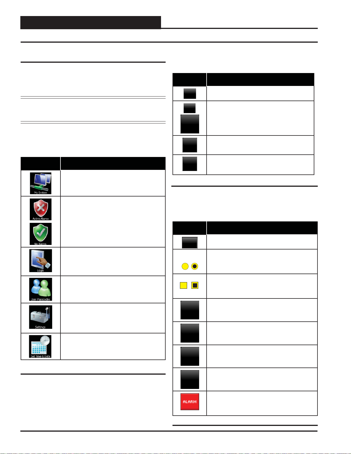
Main Screen Icons
There are six Main Screen icons. See Table 1 for a list of the Main
Screen icons and their functions.
Icon Main Screen Icons
The < My System> icon takes you to a Unit
Selection Screen which takes you directly to the
selected controller’s Status Screen.
When bright red, the < Alarms> icon takes
you to the Alarms Screen. When bright green,
no alarms are present. This icon is only useful
when your SMTS II is set for multiple managers
or network mode and you have confi gured alarm
polling using Prism 2 software.
<Esc>, <Back>, and <OK>.
Navigation Buttons
See Table 2 for a list of Navigation buttons and their functions.
Button Function
Use the < Esc> (Escape) key to exit from data
entry without saving any new data.
Use the small < Back> button located in the top
right corner of a Data Entry Screen to return to the
controller’s Status Screen. Use the large < Back>
button located at the bottom left of other screens to
return to the previous screen.
Use the < +> key to step to the next screen.
Use the < -> key to step to the previous screen.
Back
Back
Esc
+
-
Table 2: Navigation Button Functions
Selection, Confi guration, and Setpoint Buttons
See Table 3 for a list of Selection, Confi guration, and Setpoint buttons
and their functions.
Button Function
The < Login> icon takes you to the Login Screen
where you enter your passcode.
The < User Passcodes> icon takes you to the
System Manager Passcode Levels Screen if you
are a Level 3 user.
The < Settings> icon takes you to the System
Settings Screen where you can change the Backlight settings, set the System Manager address,
and enable alarm polling. System settings are
only accessible to a Level 3 user.
The < Set Time & Date> icon takes you to the
Set Time and Date Screen. Any level of user can
set the time and date.
Table 1: Main Screen Icon Functions
OK
Setpoints
Overrides
Schedules
Holidays
Use the < OK> key to save the data you just se-
lected or entered.
Touch the grey radio button to make your selection.
A white circle will designate that the item is
selected. You can only select one radio button item
per screen.
Touch the grey square selection box to make your
selection. A white square will designate that the item
is selected. You can make numerous square box
item selections per screen.
The < Setpoints> button, appearing on the control-
ler’s Status Screen, takes you directly to the controller’s Temperature Setpoint Screen.
The <Overrides> button, appearing on various
controllers’ Status Screens, takes you directly to the
controller’s Force Schedules Screen.
The < Schedules> button, appearing on various
controllers’ Status Screens, takes you directly to the
controller’s Schedule Screen.
The < Holidays> button, appearing on various
controllers’ Status Screens, takes you directly to the
controller’s Holidays Screen.
The < Alarm> button, appearing on the controller’s
Status Screen, takes you directly to the controller’s
Alarms Screen. If red, alarm(s) are present. If black,
no alarm(s) are present.
12
Revised 10/2/12
Table 3: Confi guration Selection Buttons
SMTS II Technical Guide
Page 13
Navigation
Main Screen Icons and Button Functions
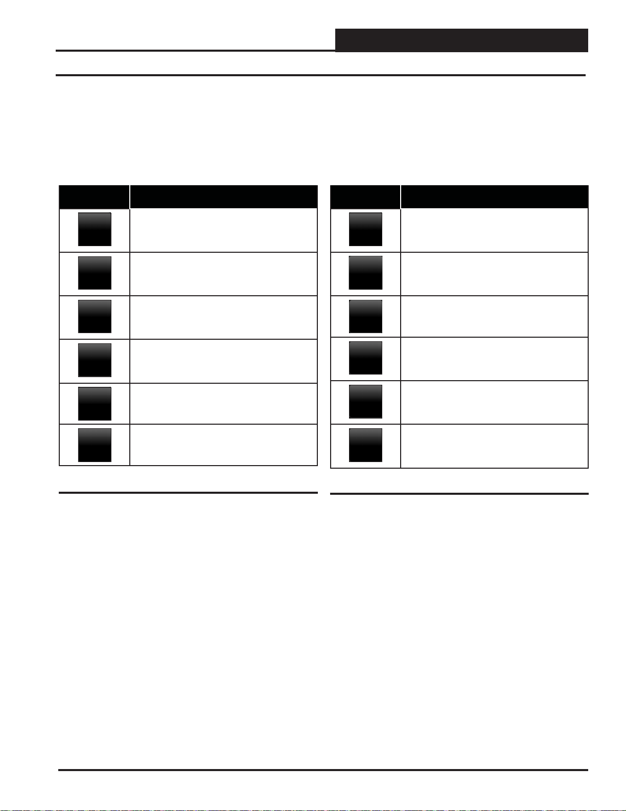
VCM, VCM-X & VCB-X Setpoint Buttons
The VCM, VCM-X & VCB-X Setpoint Buttons are located at the bottom of each controller’s Setpoints Screen. See Table 4 for a list of the
Setpoint buttons and their functions. Level 1 and Level 2 users can view
these screens and change occupied heating and cooling setpoints, but
only a Level 3 user can make changes to all setpoints.
Button Function
The < Temps> button, located at the bottom
Temps
Static
Staging
Misc
Relays
Config
of the controller’s Setpoints Screen, takes you
directly to the controller’s Temperature
Setpoints Screens.
The < Static> button, located at the bottom
of the controller’s Setpoints Screen, takes you
directly to the controller’s Static & Air Setpoints
Screens.
The < Staging> button, located at the bottom of
the controller’s Setpoints Screen, takes you
directly to the controller’s Staging Delays
Screens.
The < Misc> button, located at the controller’s
Setpoints Screen, takes you
directly to the controller’s Miscellaneous Set-
points Screens.
The <Relays> button, located at the bottom
of the controller’s Setpoints Screen, takes you
directly to the controller’s Outputs Screens.
The < Confi g> button, located at the
controller’s Setpoints Screen, takes you directly
to the controller’s Confi guration Screens.
VAV/Zone Setpoint Buttons
The VAV/Zone Setpoint Buttons are located at the bottom of the VAV/
Zone Setpoints Screen. See Table 5 for a list of the Setpoint buttons and
their functions. Level 1 and Level 2 users can view these screens and
change occupied heating and cooling setpoints, but only a Level 3 user
can change all setpoints.
Button Function
The < Temps> button, located at the bottom
Temps
Damper
Alarms
Misc
Calibrate
Config
the controller’s Setpoints Screen, takes you
directly to the controller’s Temperature Setpoints
Screens.
The < Damper/Airfl ow> button, located at the
bottom of the controller’s Setpoints Screen, takes
you directly to the controller’s Damper/Airfl ow
Setpoints Screens.
The < Alarms> button, located at the bottom
of the controller’s Setpoints Screen, takes you
directly to the controller’s Alarm Settings Screen.
The < Misc> button, located at the bottom
of the controller’s Setpoints Screen, takes you
directly to the controller’s Miscellaneous
Setpoints Screen.
The < Calibrate> button, located at the bottom
of the controller’s Setpoints Screen, takes you
directly to the controller’s Calibration Setpoints
Screen.
The < Confi g> button, located at the bottom
of the controller’s Setpoints Screen, takes you
directly to the controller’s Confi guration Setpoints
Screens.
Table 4: VCM, VCM-X & VCB-X Setpoint Icons
Table 5: VAV/Zone Setpoint Icons
SMTS II Technical Guide
13
Page 14
Main Screen Functions
Logging In
Zone
Zone
First Things First
The fi rst thing you need to do when setting up your Touch Screen is
to Login. The second thing you need to do is establish user passcodes.
The third thing you need to do is set the clock. After you complete
these simple tasks, you are ready to set your system’s settings,
view controller status screens, and change schedules and setpoints.
NOTE: Do not attempt to make changes to the Touch Screen
while the Unit Controller is initializing. This can cause
programming errors.
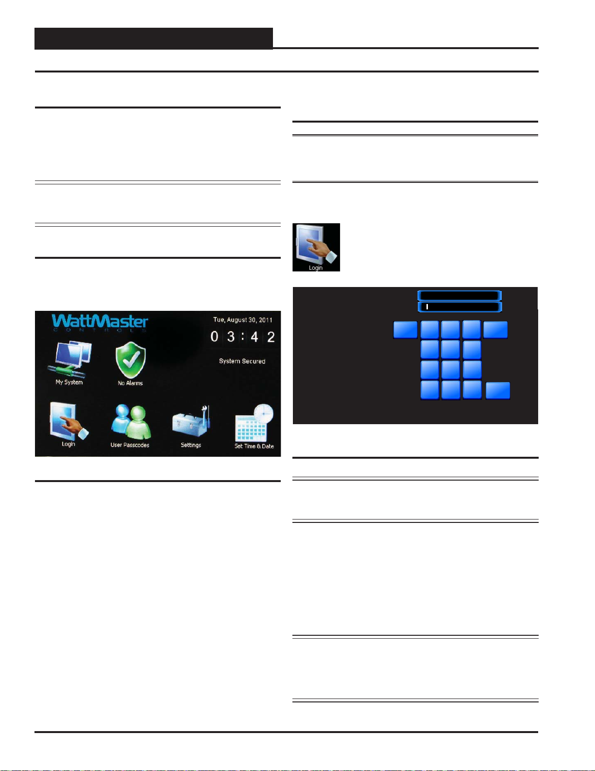
Main Screen
Once you have connected your System Manager TS II to a controller
and have powered it up with the proper power supply, the Main Screen
will appear. See Figure 9.
Entering Your System Manager
Passcode
NOTE: There are three available passcode levels. Level 1 defaults to
1111, Level 2 defaults to 2222, and Level 3 defaults to 3333. These defaults
can be changed by anyone who logs in at Level 3.
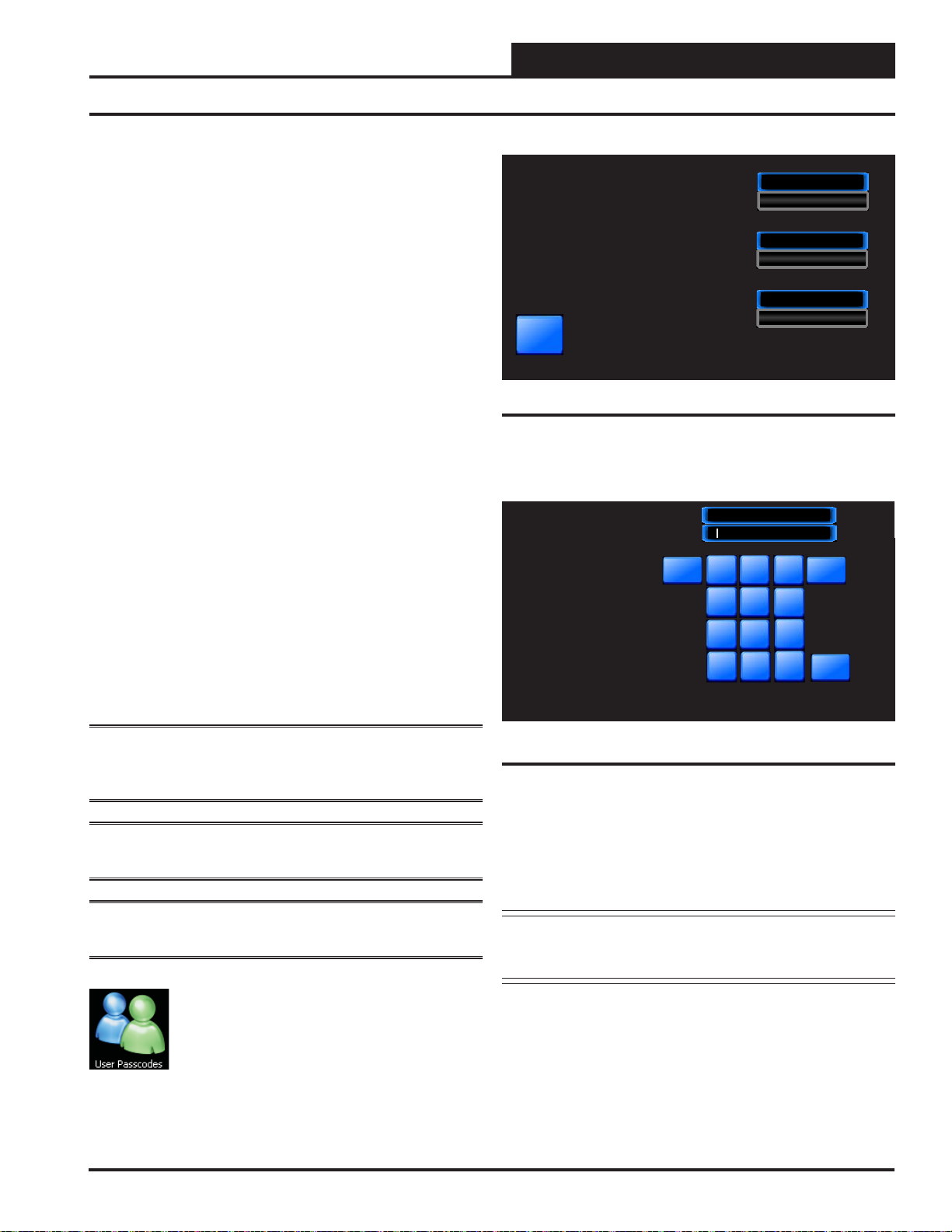
When you power-up your System Manager TS II, the message
Secured is displayed on the bottom left corner of the Main Screen.
Touch the
< Login> icon found on bottom left of the
Main Screen and type the default Level 3 passcode of
“3333” using the number keypad to gain access to all
setpoint and confi guration items. See Figure 10.
Esc
Currently: ****
2
1
4
5
7
8
-
0
3
6
9
.
DATA ENTRY
Enter the 4 digit Passcode
for the required Level.
Level #1:
Can change space setpoints.
Level #2:
Can change schedules.
Level #3:
Can change all setpoints.
System
<<
OK
Figure 9: Main Screen
Figure 10: Login Screen
NOTE: For security reasons, the current passcode characters
displayed at the top of the screen are never shown and
appear as asterisks.
Touch <OK>. Touch <Esc> if you accessed this screen by mistake and
do not wish to change the current access level.
The Login Screen will automatically close, and the passcode will be
tested against all previously defi ned passcodes to determine the pass-
code’s access level.
If 3333 is still the active Level 3 code, the status message System
Access Level 3 will now be displayed on the bottom left corner of
the Main Screen.
NOTE: System Access will automatically default to System
Secured after time set for Backlight Timeout in the
System Manager Settings Screen (see Figure 15, page
19). If timeout is set to zero, the passcode will timeout
after two minutes.
14
Revised 10/2/12
SMTS II Technical Guide
Page 15
Main Screen Functions
Editing Passcodes
Passcode Clearance Levels
Below is a list of the passcode levels, default codes, and actions that can
be performed at the various levels.
Level 0—No Passcode Needed, System
Secured
Level 0 users can view temperatures and status points. They
can also change the system date and time, but no changes
to any controller setpoints can be made.
Level 1—Default: 1111
Level 1 users can view temperatures and change space
temperature setpoints. No changes to schedules or other
settings can be made.
Level 2—Default: 2222
Level 2 users can change space temperature setpoints and
operating schedules but not confi guration settings.
Level 3—Default: 3333
Level 3 users have system manager access and can change
all setpoints and confi gurations, including default pass-
codes. Level 3 users can also access force modes. This
Level is normally reserved for qualifi ed HVAC service
personnel.
Edit Passcodes
Passcode Levels
You can limit access to critical settings
by giving the user access only to those
items needed to maintain comfort levels
or to modify operating hours.
All critical setpoints and configurations
are protected by Level #3 and should not be
accessed except by a service technician.
Back
{ Can change Space Setpoints }
{ Can change Schedules & Holidays }
{ Can change All Setpoints }
1111
Level #1 Passcode
2222
Level #2 Passcode
3333
Level #3 Passcode
Figure 11: System Manager Passcode Levels Screen
To change a passcode, touch the blue highlighted box containing the
current passcode. The keypad will appear with instructions for changing
the passcode. See Figure 12.
Esc
Currently: 1111
2
1
4
5
7
8
-
0
<<
3
6
9
OK
.
DATA ENTRY
Enter the 4 digit Passcode
for Level 1.
Level #1:
Can temporarily override schedules.
Level #2:
Can change schedules and holidays.
Level #3:
Can change user passcodes and
access force modes.
WARNING: MAKE SURE YOU CHANGE ALL PASSCODES AS SOON AS POSSIBLE TO SECURE THE
SYSTEM!
NOTE: Only a Level 3 user ( system manager level) can change Level
1, 2, and 3 passcodes.
NOTE: Do not use the same passcode for all 3 levels. If you do, each
passcode will default to Level 1.
From the Main Screen, touch the
< User Passcodes>
icon. The System Manager Passcode Levels Scr een will
appear. See Figure 11.
SMTS II Technical Guide
Figure 12: Change Passcode Screen
The current passcode will appear on the top menu bar. Type in the new
four-digit passcode. You cannot use the period or minus characters in
your passcode. Use the <<<> key if you make a mistake. Touch <Esc>
to return to the previous screen without changing the passcode. When
you have typed in the new passcode, touch <OK>. The System Manager
Passcode Levels Screen should display the passcode you entered.
NOTE: If you change the Level 3 passcode, make sure to write
it down. If you should happen to forget the Level 3
passcode, contact WattMaster Technical Support.
Touch <Back> to return to the Main Screen.
15
Page 16
Main Screen Functions
Setting the System Clock
Zone
Zone
Set Time and Date
When you fi rst power up your System Manager TS II, you will need
to change the day of the week, the time, and the month, day, and year
to the current time and date. If your system has been turned off or has
been down for a long time, you may have to do the same, although the
time and date can maintain itself for several days. Any level of user can
change the time and date settings.
The day of the week, the time, and the date appear at the top right on
the Main Screen. See Figure 9.
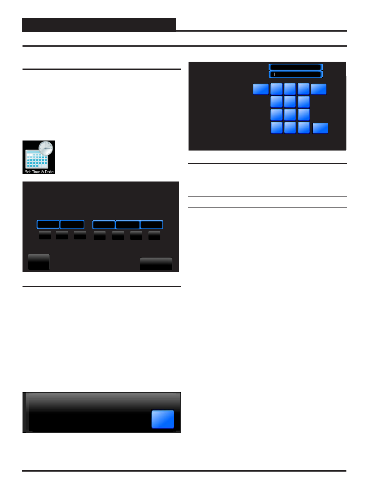
From the Main Screen, touch the < Set Time & Date>
icon. The Set Time & Date Screen will appear. See
Figure 13.
System Manager Settings
Set Time & Date
Hour Minute
14
Sun
12
Mon
Tue
Month
Wed
Day Year
Thu
Sun
Thu
16
Fri
Sun
12
Sat
Sat
Sun
Fri
1
DATA ENTRY
Set Clock Hour
Enter the Current Hour in
24 hour military format.
Example:
5:00 AM = 5
5:00 PM = 17
Hi Limit: 23
Lo Limit: 0
Esc
Currently: 10
2
1
4
5
7
8
-
0
<<
3
6
9
OK
.
Figure 14: Set Clock Hour
Set Clock Hour: Touch the number buttons to enter the current hour in
24 hour military format. Valid entries are from 0-23. Press <OK>.
NOTE: See Appendix for Military Time Conversion table.
Set Clock Minute: Touch the number buttons to enter the current
minutes. Valid entries are from 0-59. Press
Set Clock Month: Touch the number buttons to enter the current
month. Valid entries are from 1-12. Press <OK>.
<OK>.
Back
Broadcast
Figure 13: Set Time & Date Screen
In the example above, the current time and date is 2:12 PM, January 16,
2012. There is no day of the week selected yet.
Set Day of the Week: Select the day of the week by simply touching
your selection. The day of the week text will change from white to blue.
Set Hour, Minute, Month, Day, and Year: Touch the blue high-
lighted box to have each selection screen appear. See Figur es 13 & 14.
Read the instructions on each screen for entering data.
Broadcast: When you are fi nished setting the clock, touch the
<Broadcast> button to broadcast the Time and Date to all Units. The
following message will appear:
Time & Date Broadcast to All Units.
OK
Set Clock Day: Touch the number buttons to enter the current day of
the month. Valid entries are from 1-31. Touch <OK>.
Set Clock Year: Touch the number buttons to enter the current year.
Valid entries are from 0-99. Touch <OK>. Note: The year is based on
the current century; therefore, 12 = 2012. If you enter more than two
digits, e.g. 2012, the system will not recognize your entry.
16
SMTS II Technical Guide
Page 17
Main Screen Functions
System Manager Settings
System Manager Settings
Additional system settings are available under the <Settings> icon.
These include setting the Backlight Timeout, the Backlight Intensity
Percentage, the System Manager Address, Alarm Polling, and One to
One Unit Connection.
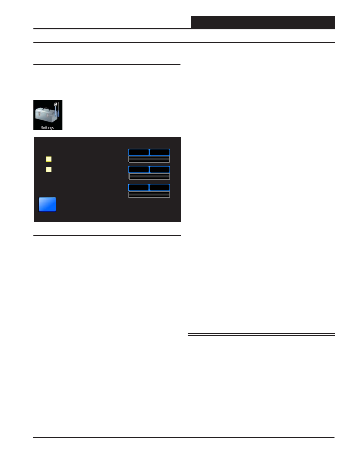
From the Main Screen, touch the < Settings> icon.
The System Manager Settings Screen will appear. See
Figure 15.
System Manager Settings
30
30
Minutes
Alarm Polling Enabled
One to One Unit Connection
Back
Figure 15: System Manager Settings Screen
Backlight Timeout
3050
Backlight Intensity
3063
System Manager Address
System Manager Version: 2.00
%
System Manager Address: Enter the address of the System Manager
TS II. 0 = Stand Alone Mode. 63 = Network System. 1-60 = Multiple
Managers based on the following defi nitions:
• Stand Alone—If your System Manager TS II is connected to
one controller and you are not using a CommLink or MiniLink
anywhere on the loop, your system is Stand Alone. If your System
Manager TS II is connected to more than one controller daisychained together and you are not using a CommLink or MiniLink
anywhere on the loop, your system is Interconnected. If you have
either a Stand Alone or Interconnected system, you must enter
<0> for Stand Alone Mode. In order to view all controllers on an
Interconnected System, make sure that One to One Unit Connec-
tion, described below, is not selected.
• Network—If you are using this System Manager TS II on a com-
munications loop that has a MiniLink or CommLink installed and
you have a single System Manager TS II for your entire system,
you must enter <63> for Network System.
• Multiple Managers—If you are using this System Manager TS
II on a communications loop, have a MiniLink or CommLink installed, and have more than one System Manager TS II, then you
need to operate in Multiple Managers Mode. Enter the address
<1-60> at which you want this particular System Manager TS II
to be set. When more than one System Manager TS II is used on
a local loop, each must be set with a unique address different from
any other device on that loop. If you want one of the System Manager TS II’s to be able to indicate alarms for the entire system, you
must enter <63> for Network System for that particular System
Manager TS II.
Backlight Timeout: This setting is actually a setting for three separate
functions—Backlight Timeout, Main Screen Timeout, and Passcode
Timeout. To set the Backlight Timeout, enter the amount of time you
wish the screen to maintain the active intensity level after the last touch
pad activity occurs. The High limit is 30 and the Low limit is 0. 0 =
No Timeout. The System Manager TS II will return to the Main Screen
display at the same rate as the Backlight Timeout, except that if set
to 0, the Main Screen will display after 2 minutes. The Passcode will
timeout at the same rate as the Backlight Timeout, except that if set to
0, the Passcode will timeout after 2 minutes and will return to System
Secured Setting.
Backlight Intensity Percentage: Enter the percentage of light level
you wish to maintain whenever touch pad activity occurs. The High limit
is 100 and the Low limit is 0.
Alarm Polling Enabled: If you wish for the system to poll for alarms,
touch the black box to the left of this item to select it. The box will
turn white and the system will immediately check all loops for alarms.
Touch <Cancel> to stop the process. If you wish to have Alarm Polling
Disabled, you must now touch the white box to deselect this option. The
box will return to its previously fully black state.
NOTE: For the System Manager TS II to poll for alarms, you
must also confi gure the unit(s) to poll for alarms on the
MiniLink Polling Device Setpoints Screen using Prism
2. See the Appendix in this guide for more information.
One to One Unit Connection: If your System Manager TS II is
directly connected to only one unit, you may wish to select this option
to bypass the Unit Selection Screen and go directly to the unit’s Status
Screen. The controller must be set to address #1 for this to work. Touch
the black box to the left of this item on the screen to select it. The box
will turn white. If you wish to deselect this option, simply touch the
box again.
System Manager V ersion: The version number of the System Man-
ager software appears on the bottom menu bar. This version number is
important to know for troubleshooting purposes.
SMTS II Technical Guide
17
Page 18
Main Screen Functions
Polling for Alarms
Zone
Zone
Alarm Polling
In order for Alarm Polling to appear on the Main Scr een, you must have
the following items in place:
1. Alarm Polling Enabled must be selected in the Systems
Settings Screen (see Figure 15, page 17).
2. You must have a MiniLink connected to your system and
have your System Manager TS II set to Network Mode.
3. You must confi gure each unit to poll for alarms on the
MiniLink Polling Device Setpoint Screen using Prism 2.
See the Appendix in this guide for more information.
The < Alarms> icon on the Main Screen allows you to check for
alarms, review alarms, and clear alarms. Only a Level 3 user can clear
the alarm log.
A green
Screen when no alarms are present. This icon changes to
a red < Active Alarms> icon when alarms are present.
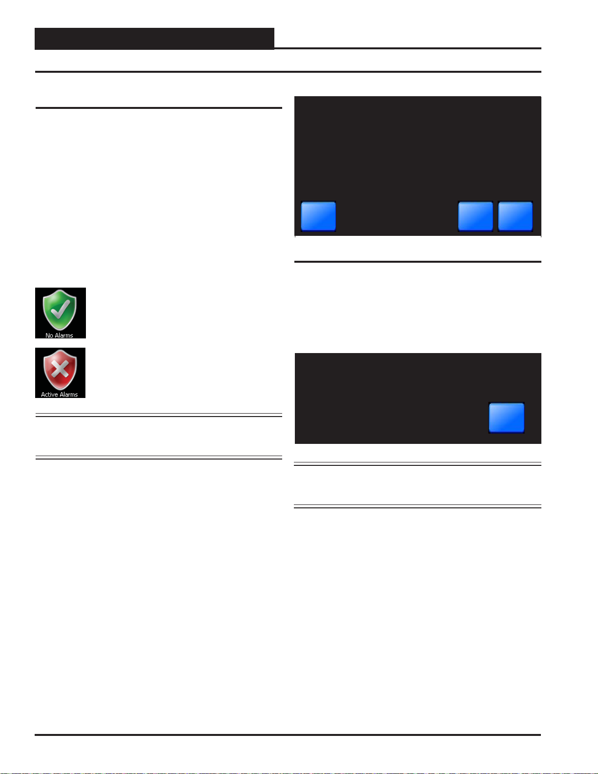
To check for alarms, review alarms, or clear alarms,
from the Main Screen, touch the < Active Alarms>
icon. The System Alarm Status Screen will appear. See
Figure 16.
< No Alar ms> icon appears on the Main
System Alarm Status
Checking
Back
Clear All
Next Unit
Figure 16: System Alarm Status Screen
Next Unit: Touch <Next Unit> to access the next unit’s alarms.
Clear All: Touch <Clear All> to clear all alarms logs. Active alarms
will remain. You must be a Level 3 user to access this option. When all
alarms have cleared, the following message will appear on the screen:
All alarms cleared.
Any remaining active alarms will re-appear.
NOTE: Even if you don’t set up Alarm Polling using Prism 2,
a controller’s fi rst status screen will still alert you of an
active alarm.
OK
NOTE: Y ou can also view alarms while in individual controller’s
status screens. For more information, see pages 21, 22
& 63.
18
SMTS II Technical Guide
Page 19
VCM, VCM-X & VCB-X Controllers
Selecting Units and Viewing VCM, VCM-X & VCB-X Status Screens
My System Unit Selection
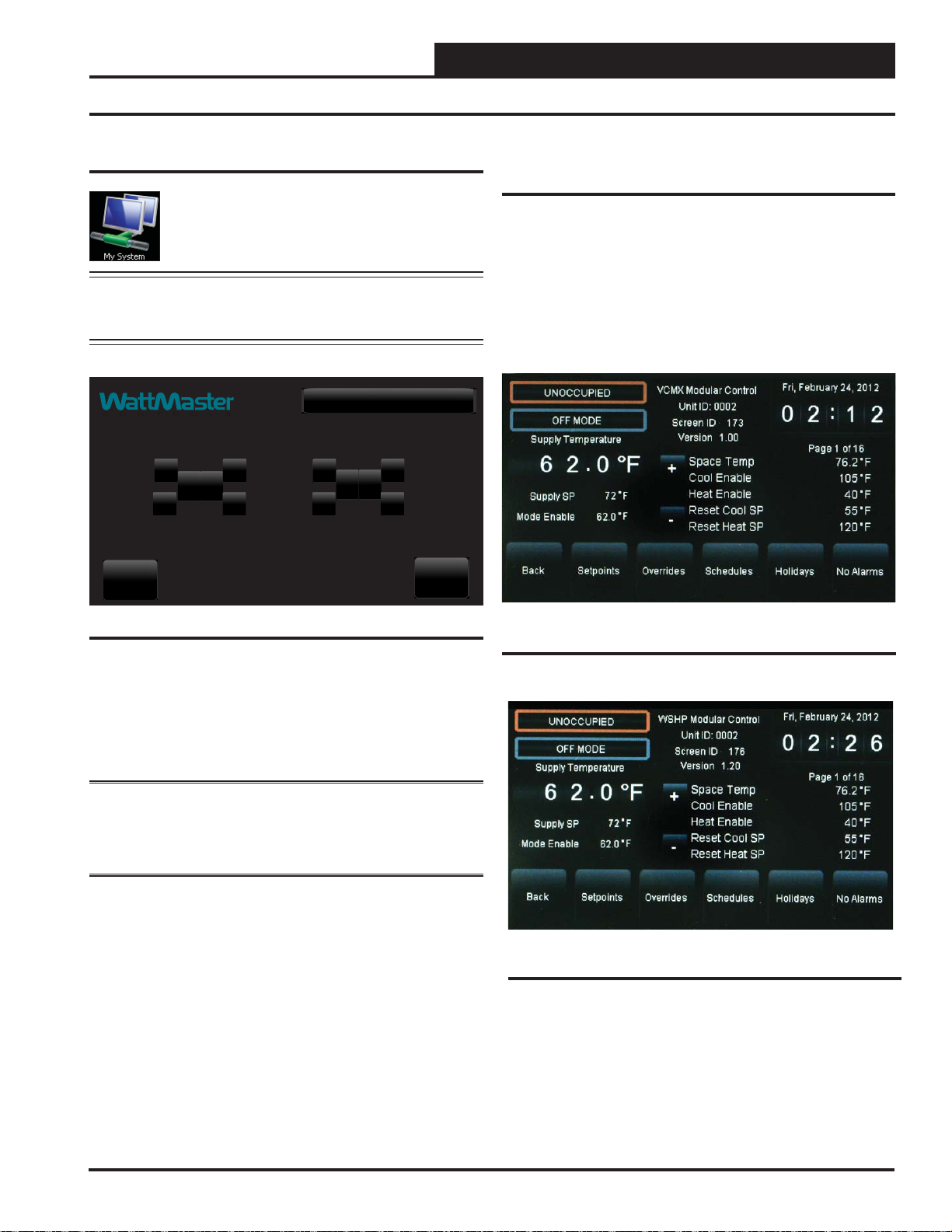
From the Main Screen, touch the < My System> icon.
The Selected Unit Screen will appear. See Figure 17.
NOTE: If you have chosen the One to One Unit Connection
in the System Manager Settings Screen, this screen will
not appear. Instead, the unit’s Status Screen will appear.
Selected Unit [Loop 1 - Unit 1]
+ + + +
1
0
10
- - - -
Back
GO
Viewing VCM, VCM-X & VCB-X Status
Screens
Figures 18, 19, 20 & 21 depict the fi rst Controller Status Screens.
Notice that the controller is identifi ed by loop number and unit number
- in this case, 0102 represents Loop 1, Unit 2. Images vary based on
controller type.
While in the Status Screen, touch the <+> and <-> buttons to view more
status screens displaying relays and operating setpoints. These screens
roll back to the fi rst Status Screen.
Figure 17: Unit Selection Screen
In Figure 17, Loop 1 and Unit 1 are selected as indicated in the fi gure
with white text. They also appear in the Top Menu Bar in brackets.
Use the <+> and <-> buttons to move up and down through the loops
and units. Enter the desired Loop # and Unit # and then touch <GO>
to access the unit’s Status Screen.
NOTE: Instructi ons f or confi gurations and setpoints are included in
this guide separately for V CM/VCM- X Controllers, VCB-X Controllers,
and V A V/Zone Controllers. See page 25 for VCM/VCM-X Controllers,
page 42 for VCB-X Controllers, and page 63 for V A V/Zone Controllers.
Figure 18: VCM-X & VCM-X Modular Controller
Status Screen 1
Figure 19: VCM-X WSHP Controller (Tulsa) Status
Screen 1
SMTS II Technical Guide
19
Page 20
Zone
VCM, VCM-X & VCB-X Controllers
Viewing VCM, VCM-X & VCB-X Status Screens
Zone
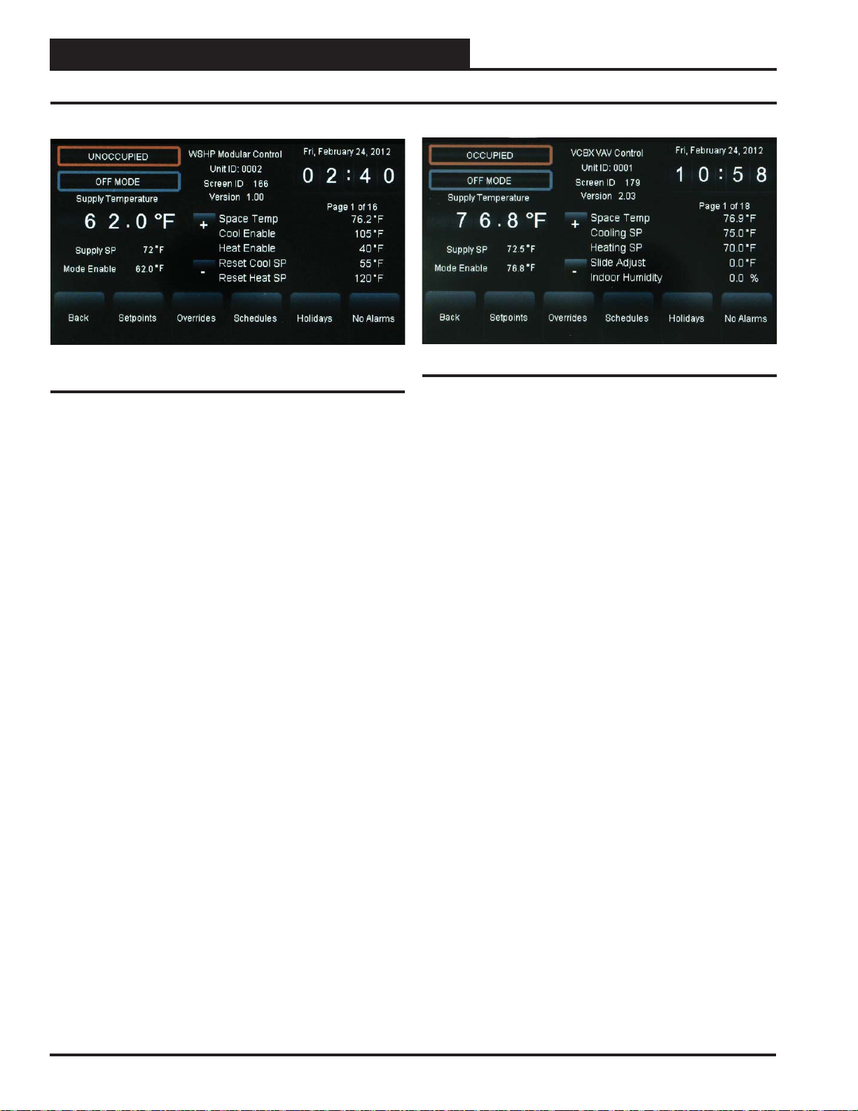
Figure 20: VCM-X WSHP Controller (Coil) Status
Screen 1
Figure 21: VCB-X Controller Status Screen 1
20
SMTS II Technical Guide
Page 21
VCM, VCM-X & VCB-X Controllers
Viewing and Enabling/Disabling VCM, VCM-X & Module Alarms
Viewing VCM, VCM-X & Module
Alarm Status
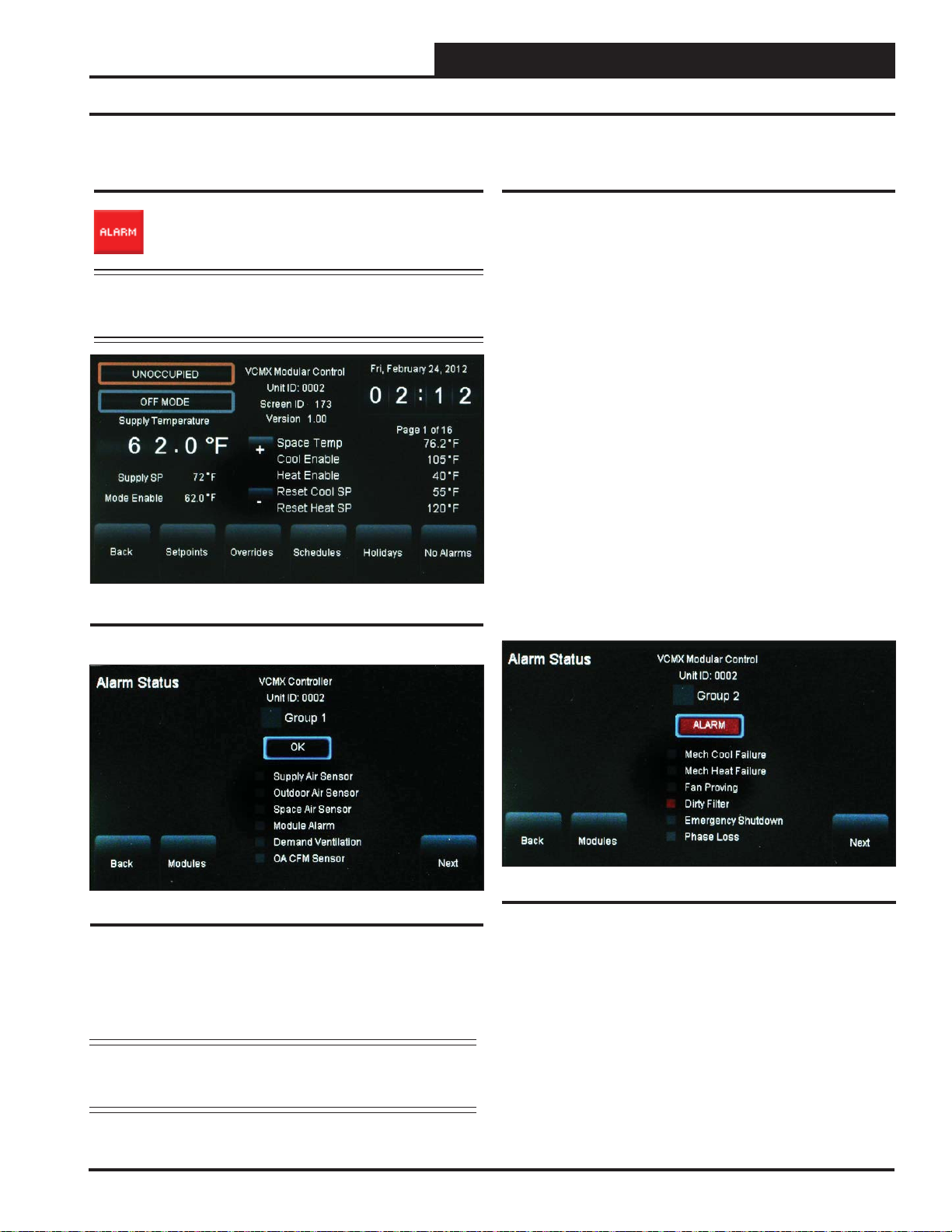
To view alarm status, touch the <ALARM> button on the
unit’s fi rst Status Scr een. See Figure 22. The Alarm Status
Screen will display. See Figure 23.
NOTE: The < ALARM> button only appears on the screen if the
unit has an active alarm condition. Only a Level 3 user
has the option to enable or disable each type of alarm.
Figure 22: VCM-X Controller Status Screen 1
Enabling/Disabling VCM, VCM-X &
Module Alarms
Alarm confi guration is accessed by touching the <ALARM> button on
the lower right of the unit’s fi rst Status Screen. See Figure 22. Only a
Level 3 user can confi gure alarms. Touch the <Next> button to go to
the next Alarm Status Screen.
In addition to simply viewing alarms, the Alarm Status Screen can also
be used for enabling and disabling alarms that will be emailed or texted.
The emailing and texting feature will only work if Prism 2 is running
and has emailing capability.
The alarms must fi rst be confi gured using Prism 2 software. See the
Appendix in this guide for instructions.
Once the alarm settings have been established in Prism 2, the settings
you choose in the Alarm Status Screen will be stored in the controller
so that you will not have to reconfi gure the alarms for that controller in
Prism 2. Once confi guration is complete, Prism 2 does not have to be
running in order to view alarms on individual Alarm Status Screens in
the System Manager TS II. However, as mentioned previously, Prism 2
does have to be running for emailing or texting alarms to occur.
To enable an alarm category—Sensors, Mechanical, Fail Modes—simply
touch the black square next to Group 1, Group 2, and/or Group 3. A white
box designates that the alarm category is enabled. To disable an alarm
category, simply touch the square again. A grey box designates that the
alarm category is disabled. See Figure 23 for an example.
Figure 23: VCM-X Controller Alarm Status Screen
Touch the
the <Modules> button to go to the Head Pressure Module Alarms
Screen, Dual/Full Digital Module Alarms Screen, and Heat Pump
Module Alarms Screen.
<Next> button to go to the next Alarm Status Screen. Touch
NOTE: Even if you don’t set up Alarm Polling using Prism 2,
a controller’s fi rst status screen will still alert you of an
active alarm.
SMTS II Technical Guide
Figure 24: VCM-X Controller Alarm Screen
In the example above (Figure 24), there is an ALARM (designated by the
word ALARM in red.) There is a red box in front of Dirty Filter , designating the alarm. If there is no alarm condition, the word OK appears in a
box below the Group Number (as shown in Figure 23).
Touch the <Next> button to go to the next Alarm Status Screen. Touch
the <Modules> button to go to the Head Pressure Module Alarms
Screen, Dual/Full Digital Module Alarm Scr een, and Heat Pump Module
Alarms Screen.
21
Page 22
Zone
VCM, VCM-X & VCB-X Controllers
Viewing and Enabling/Disabling VCB-X Alarms
Zone
Viewing VCB-X Alarm Status
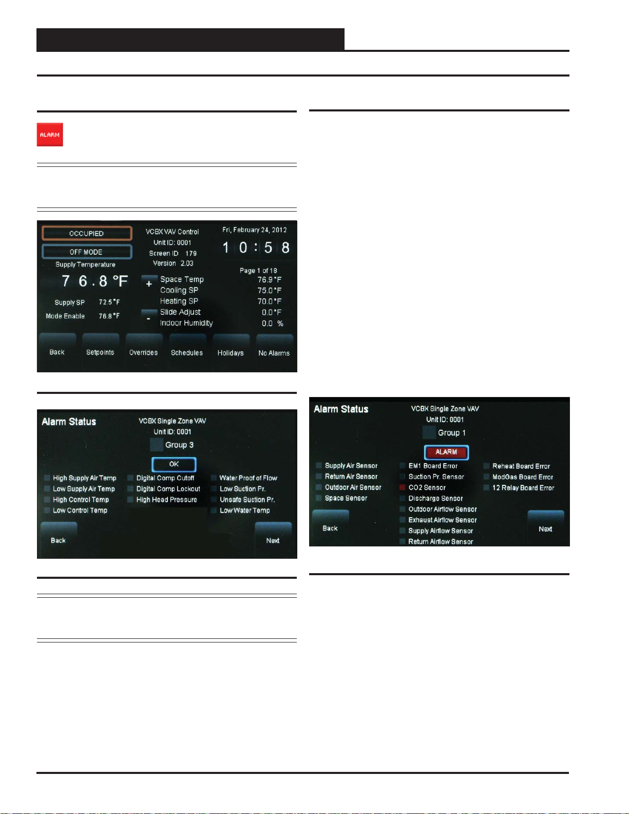
To view alarm status, touch the <ALARM> button on the
unit’s fi rst Status Screen. See Figure 25. The Alarm Status
Screen will display. See Figure 26.
NOTE: The < ALARM> button only appears on the screen if the
unit has an active alarm condition. Only a Level 3 user
has the option to enable or disable each type of alarm.
Figure 25: VCB-X Controller Status Screen 1
Enabling/Disabling VCB-X Alarms
Alarm confi guration is accessed by touching the <ALARM> button on
the lower right of the unit’s fi rst Status Screen. See Figure 25. Only a
Level 3 user can confi gure alarms.
In addition to simply viewing alarms, the Alarm Status Screen can also
be used for enabling and disabling alarms that will be emailed or texted.
The emailing and texting feature will only work if Prism 2 is running
and has emailing capability.
The alarms must fi rst be confi gured using Prism 2 software. See the
Appendix in this guide for instructions.
Once the alarm settings have been established in Prism 2, the settings
you choose in the Alarm Status Screen will be stored in the controller
so that you will not have to reconfi gure the alarms for that controller in
Prism 2. Once confi guration is complete, Prism 2 does not have to be
running in order to view alarms on individual Alarm Status Screens in
the System Manager TS II. However, as mentioned previously, Prism 2
does have to be running for emailing or texting alarms to occur.
To enable an alarm category—Sensors, Mechanical, Fail Modes—simply
touch the black square next to Group 1, Group 2, and/or Group 3. A white
box designates that the alarm category is enabled. To disable an alarm
category, simply touch the square again. A grey box designates that the
alarm category is disabled. See Figure 26 for an example.
Figure 26: VCB-X Controller Alarm Status Screen
NOTE: Even if you don’t set up Alarm Polling using Prism 2,
a controller’s fi rst status screen will still alert you of an
active alarm.
Touch the
<Next> button to go to the next Alarm Status Screen.
22
Figure 27: VCB-X Controller Alarm Screen
In the example above (Figure 27), there is an ALARM (designated by
the word ALARM in red.) There is a red box in front of CO2 Sensor,
designating the alarm. If there is no alarm condition, the word OK appears in a box below the Group Number (as shown in Figure 26).
Touch the <Next> button to go to the next Alarm Status Screen.
SMTS II Technical Guide
Page 23
VCM, VCM-X & VCB-X Controllers
Viewing and Setting Schedules
To view and set schedules for VCM, VCM-X, and VCB-X controllers,
touch the <Schedules> button found at the bottom of the Status Scr een
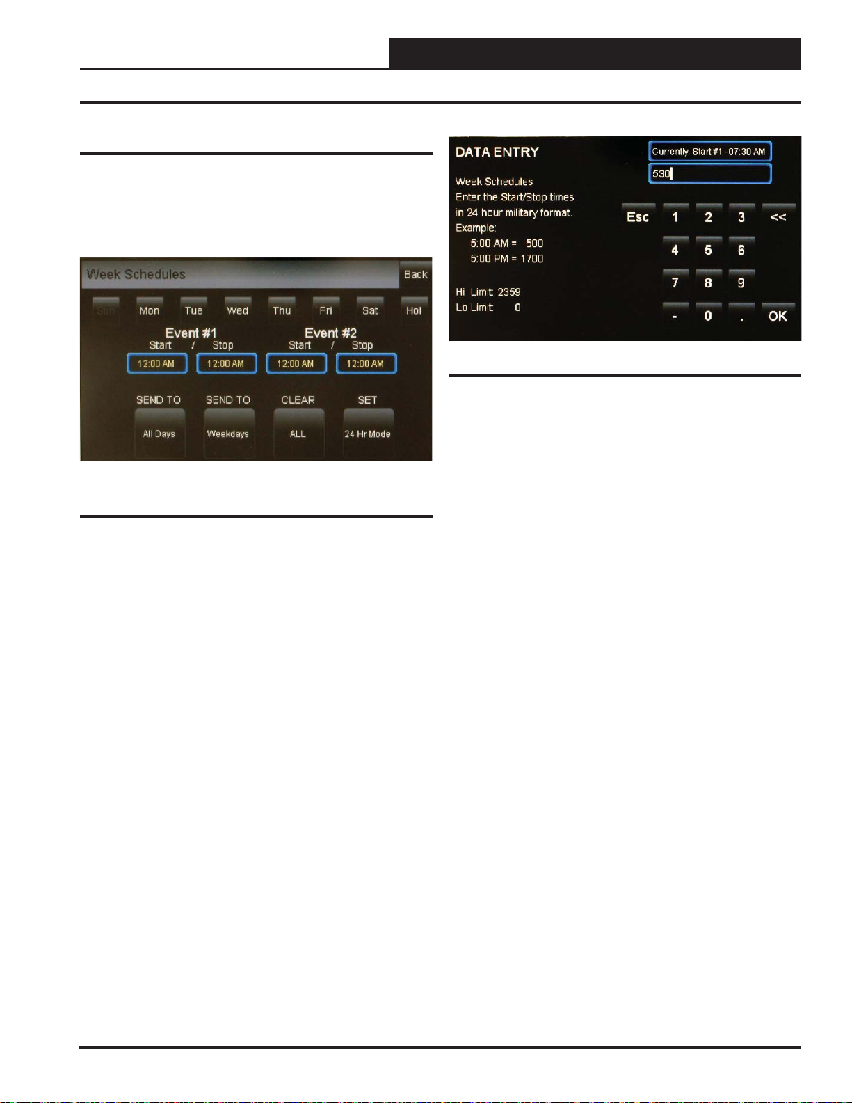
(Figure 22 & 25). The Schedules Screen will appear. See Figure 28.
The default day will be Sunday and the default event start/stop times
will be midnight.
Viewing and Setting Schedules
Figure 29: Schedule Times Screen
Touch <OK> to save the time you entered or touch <Esc> to exit the
Schedule Times Screen without changing the time and return to the
Schedules Screen (Figure 28).
Figure 28: VCM / VCM-X / VCB-X Controller
Schedules Screen
A Level 2 user can set two schedules per day for individual days of the
week, all weekdays, weekends, and holidays. All times are entered in
military time format.
If you wish to enter a schedule for a certain day of the week, fi rst touch
the day of the week at the top of the screen. Otherwise, the day defaults
to Sunday. Touch the start and stop time for each Event and enter the
desired times. See Figure 29. All times must be entered in military time
format. See the Military Time Table - Table 8 - in the Appendix.
To eliminate a schedule from any event, simply enter a zero for the
Start and Stop time for that day. The screen will display 12:00 am for
both the Start and Stop times, indicating that the equipment will not
activate on that day.
Once back at the Schedules Screen, you can continue setting schedules
day by day or use following options:
SEND TO <All Days> - Touch this button to send the schedule appearing
on the screen to all days of the week, except for holidays.
SEND TO <Weekdays> - Touch this button to send the schedule to
weekdays only. You will need to set up a separate schedule for Saturday
and Sunday when selecting this option.
CLEAR <All Schedules> - Touch this button to clear all schedules.
SET <24 Hr Mode> - Touch this button to have the system run con-
tinuously, 24 hours a day, 7 days a week including holidays. All event
times will display 11:59 PM.
SMTS II Technical Guide
23
Page 24
Zone
VCM, VCM-X & VCB-X Controllers
Zone
Viewing and Setting Holidays and Forcing Schedules
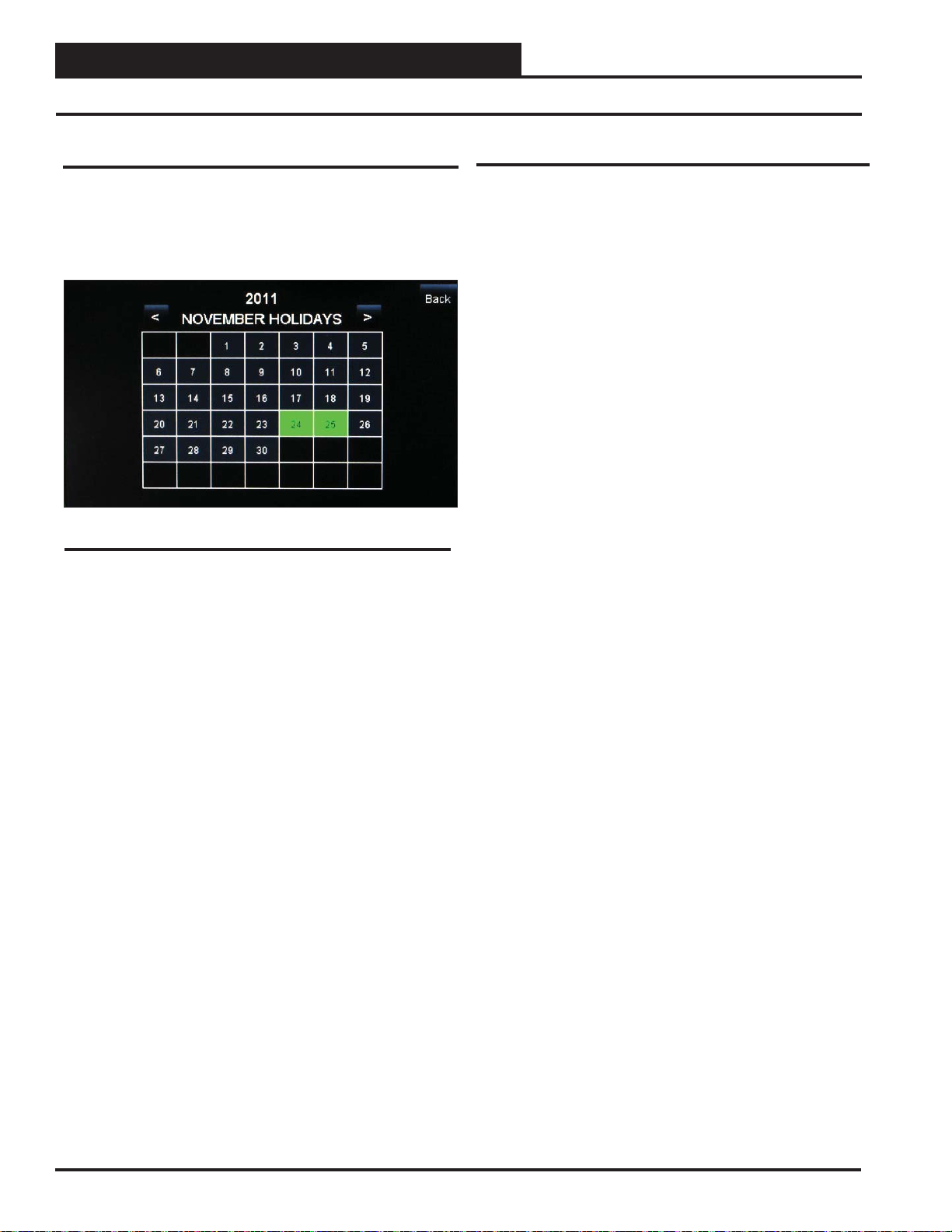
Viewing and Setting Holidays
To view and set holidays for a VCM/VCM-X/VCB-X controller, touch
the
< Holidays> button found at the bottom of the Status Screen (Figures
22 & 25). The Holidays Schedule Screen will appear . See Figure 30. The
holidays in the screen will initially not be set. You can only set holidays
for the current year. You must be a Level 2 user in order to set holidays.
Figure 30: Holidays Schedule Screen
Simply touch the day(s) of the month to select holidays. Touch the
<<> button to go back one month and the <>> button to go forward
one month.
Schedule Override
To Force Schedules, from the VCM, VCM-X or VCB-X Main Status
Screen, touch the Occupied/Unoccupied wording located below the time
and date display. The following options will appear:
Schedule Auto Mode
Touch the radio button to select the schedule option. Default is Schedule
AUTO Mode. This selection will remain in effect unless it is changed
again on this screen. Schedule overrides do not automatically time out
after a certain period of time.
Schedule AUT O Mode—Select this to restore normal
schedule operations.
Schedule FORCED ON—Select this to Force the unit into
continuous Occupied Mode operation.
Schedule FORCED OFF—Select this to Force the unit
into continuous Unoccupied Mode operation.
There are 14 holiday periods available for each year. These holiday periods can be a single day or they can span days, weeks, or even months.
For example, if you want to schedule a summer break, you need only
schedule one holiday period to defi ne a two or three month break from
operating in the occupied mode.
Every defi ned holiday uses the Holiday operating schedule programmed
in the controller’s Schedules Screen.
Holidays can only b e pr ogrammed for the c urrent year. You cannot progra m
ho lid ays be for e th e n ext yea r oc curs . Holidays do not automatically adjust for
the new year, so you will need to access this screen after the new year and
make necessary adjustments to the days that fl oat, such as Memorial Day.
24
SMTS II Technical Guide
Page 25
VCM & VCM-X Controllers
Accessing and Entering VCM & VCM-X Setpoints
Accessing and Entering VCM & VCM-X
Setpoints
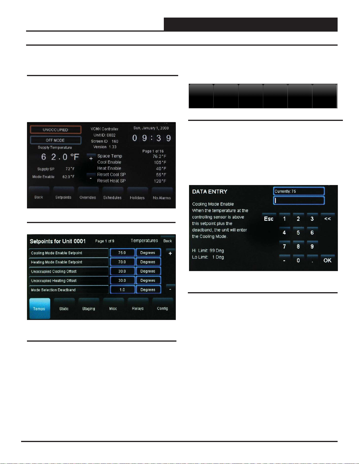
While in the VCM-X Status Screen (see Figure 31), touch the < Set-
points> button found on the bottom menu bar . The VCM-X Controller’s
Temperature Setpoints Screen will appear. See Figure 32.
Level 1 and Level 2 users can change occupied space temperature set-
points, but only Level 3 users can change all setpoints.
Figure 31: VCM-X Controller Status Screen
Individual setpoint and confi guration buttons are located at the bot-
tom of the Setpoint Screens. See Figure 33. Simply touch a specifi c
button to access that category.
Temps
Static
Staging
Misc
Relays
Config
Figure 33: VCM / VCM-X Setpoint Buttons
Within each Setpoint Screen, touch the < Status> button to return
to the Status Screen or touch < Home> to return to the Main Screen.
Use the <+> and <-> buttons to scroll through the setpoints and
confi gurations. Simply touch the blue highlighted box to change the
setpoint. Each setpoint data entry screen will provide a defi nition of
the setpoint and specifi c instructions for entering the setpoint and
will include the setpoint range as in the example below, Figure 34.
Figure 32: VCM-X Controller Temperature Setpoints
Screen
SMTS II Technical Guide
Figure 34: VCM-X Cooling Mode Setpoint Data Entry
Screen
Touch <OK> to have the system accept the new value. If you enter
a setpoint that is not in the valid range, the setpoint will remain as is
and will not change.
Each setpoint data entry screen is self-explanatory; however, each
setpoint and confi guration is explained in the next section, Confi gur-
ing VCM-X Setpoints. To easily reference a particular setpoint or
confi guration, refer to the Index.
25
Page 26
VCM & VCM-X Controllers
VCM & VCM-X Confi guration
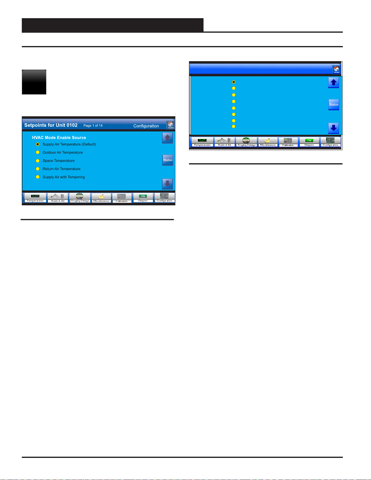
VCM-X Confi guration
Touch the < Confi guration> button to access the
Config
ton next to your selection. For screens with square buttons, touch one or
more square buttons to make your confi guration selections for the unit.
Figure 35: VCM-X Confi guration Screen 1
HVAC Mode Enable Source
Touch the radio button to select the Temperature Sensor that will determine the Heating, Cooling, or Vent Mode of operation. The available
selections are as follows:
Supply Air Temperature—This is typical for VAV
applications. Occupied Cooling with Morning Warm-up.
Outdoor Air Temperature—This is for 100% Outdoor
Air (MUA) units. Dehumidifi cation utilizing a Dewpoint
Calculation if equipped with an Outdoor Air Humidity
Sensor.
Space Temperature—This is for any unit that conditions
a space and is not 100% Outdoor air. Occupied/Unoccu pied Heating, Cooling, and Vent Modes of operation.
Return Air Temperature—This selection can be used
when an Average Building Temperature (the Return Air
Temperature) needs to determine Heating, Cooling, and
Vent Modes of operation.
Confi guration Setpoints Screens.
For screens that contain radio buttons, touch the radio but-
Setpoints for Unit 0102
Reset Source
Page 2 of 14
No Reset
Space Temperature
Return Air Temperature
External Analog Input
Fan VFD Signal Percentage
Outdoor Air Temperature
Single Zone VAV
Single Zone VAV w/CV Heat
Configuration
Figure 36: VCM-X Confi guration Screen 2
HVAC Reset Source
The Supply Air Heating and Cooling Temperature Setpoints can be reset
using various input sources. Default is No Reset. Touch the radio button
to select the desired Reset Source for Supply Air Temperature Reset.
The Single Zone VAV option should be selected in applications where
the Supply Fan VFD speed is reset based on the Space Temperature. If
you select No Reset, then neither the Supply Air Setpoint nor Supply
Fan VFD Reset will occur. The available selections are as follows:
No Reset
Space T emperature
Return Air Temperature
External Analog Input
Fan VFD Signal Percentage
Outdoor Air Temperatur
Single Zone VAV
Single Zone VAV w/ CV Heat
Supply Air w/ Supply Air Tempering—This selection is
for VAV “cooling only” applications where because of cold
outdoor temperatures, even at minimum damper position,
you may need to enable heat to maintain the cooling near its
Cooling Supply Air Setpoint. When heat is enabled during
this sequence, it will control to a non-adjustable setpoint
that is 2ºF less than the Cooling Supply Air Setpoint.
26
Revised 4/21/15
SMTS II Technical Guide
Page 27

VCM & VCM-X Controllers
VCM & VCM-X Confi guration
Setpoints for Unit 0102
Heat Pump Control
Reversing Valve Used for Cooling
Fan Proving Switch Installed
Fan Cycles with Heating & Cooling
Has Static Pressure Control
Controls Economizer
Economizer Title 24 Option
Page 3 of 14
Configuration
Figure 37: VCM-X Confi guration Screen 3
Heat Pump Control
Select this item if the HVAC unit is a Heat Pump.
Reversing Valve Used for Cooling
Select this item if your Heat Pump unit activates its reversing valve during the Cooling operation. Do not select this item if your Heat Pump unit
activates its reversing valve during the Heating operation.
Fan Proving Switch Installed
Select this item if your HVAC unit has a fan proving switch installed.
Figure 38: VCM-X Confi guration Screen 4
Outdoor RH Sensor Installed
Select this item if the HVAC unit is equipped with an Outdoor Air
Humidity Sensor.
Indoor RH Sensor Installed
Select this item if the HVAC unit is equipped with an Indoor Air Humidity Sensor
Has Humidity Control
Select this item if your system has Dehumidifi cation control.
Fan Cycles with Heating & Cooling
Select this item if you want the HVAC unit’s Supply Fan to only run
during Heating, Cooling, or Dehumidifi cation Modes. DO NOT select
this item if you want the HVAC unit’s Supply Fan to run continuously
while in the Occupied Mode, regardless of the Heating, Cooling, or
Dehumidifi cation Modes.
Has Static Pressure Control
Select this item if the HV AC unit has a Supply Fan that delivers a V ariable
Volume of Air using a VFD or a Bypass Damper to maintain Duct Static
Pressure. DO NOT select this item if the HVAC unit has a Supply Fan
that delivers a Constant Volume of air. If you have a VFD on a constant
volume unit, select this option for Filter Loading Control.
Controls Economizer
Select this item if the VCM-X is controlling the economizer.
Economizer Title 24 Option
Select this item if your unit has Title 24 Economizer operation.
Has Night Humidity Control
Select this item if your system has Dehumidifi cation control during
unoccupied hours. Unoccupied Dehumidifi cation is activated based on
Indoor Air Humidity only.
Humidity Control Has Priority
Select this item if Dehumidifi cation is a priority during the Occupied
Mode. Priority means that the Cooling stages will activate based on the
Coil temperature, and Reheat will be used regardless of Heating, Cooling, or Vent Modes of operation.
Emergency Shutdown Enabled
Select this item if an emergency shutdown device is connected to the
binary input. If the shutdown is active, the Supply Fan, Heating, and
Cooling Relay outputs will be disabled.
SMTS II Technical Guide
Revised 4/21/15
27
Page 28

VCM & VCM-X Controllers
VCM & VCM-X Confi guration
Figure 39: VCM-X Confi guration Screen 5
Has Building Pressure Mod Control
Select this item if your system needs Modulating Building Pressure Control. Modulating building pressure control is used for a VFD exhaust fan
or a modulating exhaust fan damper actuator for direct acting building
pressure control. Modulating building pressure control is also used for a
modulating outdoor air damper actuator or a supply fan VFD for reverse
acting building pressure control.
Building Pressure Reverse Acting
Select this item if your system needs Reverse Acting Building Pressure
control. On a drop in Building Pressure below the Building Static Pressure Setpoint the Outdoor Air Damper will modulate open to increase
pressure or the supply Fan VFD will ramp-up.
Building Pr. Output is 2-10 VDC
Select this item if your application needs a 2-10 VDC Building Pressure
Output Signal as required by the device you are using to control the pressure. Do not select this item if your application needs a 0-10 VDC signal.
Use Heat During Re-Heat
Select this item if your application needs to use unit heat during Dehumidifi cation to supplement Reheat. If Reheat is not available, this selection
will allow the unit heat to operate in place of Reheat.
Outdoor Air Damper Control Based on Airfl ow CFM
Select this item to modulate the outdoor damper based on airfl ow setpoint.
Figure 40: VCM-X Confi guration Screen 6
Has Modulating Cooling
Select this item if the HVAC unit is controlling Modulating Cooling
through use of a modulating chilled water valve or a digital compressor.
Modulating Cooling is Reverse Acting
Select this item if Modulating Cooling requires 0 VDC to open and 10
VDC to close. You cannot use a reverse acting signal your application
is using a digital compressor.
Has Modulating Heating
Select this item if the HVAC unit is controlling Modulating Heating
through use of a modulating hot water valve, modulating steam valve,
or a SCR controlled electric heater.
Modulating Heating is Reverse Acting
Select this item if Modulating Heating requires 0 VDC to open and 10
VDC to close.
Has Return Bypass Control
Select this item if your HV AC unit requires Return Air Bypass Control.
Full Digital Module Installed, Dual Digital Module Installed,
or using VCM-X WSHP Controller (VCM-X Modular or V CM-X
WSHP)
Select this item if you have multiple Digital Scroll Compressors installed
on your system.
Head Pressure Module Installed ( VCM-X Modular, VCM-X
WSHP)
Select this item if you have a Head Pressure Module installed on your
system.
28
SMTS II Technical Guide
Page 29

VCM & VCM-X Controllers
VCM & VCM-X Confi guration
Setpoints for Unit 0102
Has Demand Ventilation Control
Condenser HP Module Installed
Page 7 of 14
Configuration
Figure 41: VCM-X Confi guration Screen 7
Has Demand Ventilation Control
Select this item if the HVAC unit has demand ventilation control.
Condenser HP Module Installed
Select this item if the HVAC unit has split condensers.
Figure 42: VCM-X Confi guration Screen 8
Broadcast Real Time Clock to VAV Boxes
Select this item to have the HVAC unit broadcast the real time clock to
all controllers on its local loop. This broadcast sends the time from the
VCM-X’s Internal Time Clock to all controllers on its local loop. This
broadcast needs to be confi gured on a VAV or Zoning System using the
VCM-X with Orion VAV/Zone controllers. A network communications
device is required in order for this feature to operate, but can also be
used to synchronize all controllers on the local loop
Broadcast Supply Air to VAV Boxes
Select this item to broadcast the VCM-X’s Supply Air Temperature to
all controllers on its local loop. This broadcast needs to be confi gured
on a VAV or Zoning System using the VCM-X with Orion VAV/Zone
Controllers. A network communications device is required in order for
this feature to operate.
SMTS II Technical Guide
Broadcast AHU Schedule to VAV Boxes
You must select this item if you have VAV/Zone controllers connected
to the VCM-X controller. This will broadcast the Occupied and Unoccupied Schedule of the VCM-X controller to all VAV/Zone controllers
on the local loop.
Broadcast Main Fan and Heat Status to VAV Boxes
Select this item to broadcast the VCM-X’s Supply Fan and Heating
Status to all controllers on its local loop. This broadcast needs to be
confi gured on a VAV or Zoning System using the VCM-X with Orion
VAV/Zone Controllers. A network communications device is required
in order for this feature to operate.
Revised 4/21/15
29
Page 30

VCM & VCM-X Controllers
VCM & VCM-X Confi guration
Figure 43: VCM-X Confi guration Screen 9
Broadcast Outdoor Air to All Other Units
Select this item to broadcast the VCM-X’s Outdoor Air T emperature Reading to other HVAC units on the local loop if they are not equipped with
their own Outdoor Air Temperature sensors. A network communications
device is needed in order for this feature to operate.
Broadcast Relative Humidity to All Other Units
Select this item if to have the VCM-X broadcast its Outdoor Air Humidity reading to other HVAC units if they are not equipped with their own
Outdoor Air Humidity sensors. A network communications device is
required in order for this feature to operate.
Force Max Damper During Warm-Up & Night Heat
Select this item to ensure the VAV/Zone Controllers will drive their
dampers to the Max Airfl ow Damper Position during Morning Warm-up.
This is important to allow the proper amount of airfl ow for Heating in
the HVAC unit.
Force Fixed Damper During Warm-Up & Night Heat
Select this item to have all VAV/Zone controllers connected to this VCMX controller forced to their “Fixed Airfl ow” Position during the Morning
Warm-up Mode of operation. See the VAV/Zone controller Setpoint
Screens for setting of the “Fixed Airfl ow” position.
One HVAC Unit with Boxes on Multiple Loops
This selection allows other VAV/Zone controllers connected on additional
local loops to receive the required broadcasts. This is only allowed when
you have a single VCM-X controller with VAV/Zone controllers on
multiple loops. Other VCM-X or add-on devices may be connected, but
no other VCM-X with VAV/Zone controllers can be connected on the
system. Select this item to have real time, supply air, and main supply
fan and heating status broadcast to all local loops on the entire system,
not just the local loop the VCM-X controller is on. This is normally only
required if you have a large HVAC unit that requires more than the 58
VAV/Zone controllers normally allowed on the local loop.
Figure 44: VCM-X Confi guration Screen 10
Modulating Cooling Output
Select either a 0-10 VDC signal or 2-10 VDC signal to a Modulating
Cooling source such as a Chilled Water Valve or select a 1.5-5 VDC
signal to a Digital Compressor.
Figure 45: VCM-X Confi guration Screen 11
Modulating Heating Output
Select 0-10 VDC signal or 2-10 VDC signal to a Modulating Heating
source such as a Hot Water Valve or SCR Electric Heater.
30
SMTS II Technical Guide
Page 31

VCM & VCM-X Controllers
VCM & VCM-X Confi guration
Figure 46: VCM-X Confi guration Screen 12
Carbon Dioxide Sensor Scaling
If you have a CO2 sensor installed on your system, select whether it is a
current (4-20 mA) sensor or a voltage (0-10 VDC) sensor. If you have
a communicating CO2 sensor, select Voltage Sensor.
Figure 47: VCM-X Confi guration Screen 13
Refrigerant
Select whether your HVAC unit is using R-22 or R-410A refrigerant.
Setpoints for Unit 0102
Airflow
Outside Airflow Sensor Installed
Return Airflow Sensor Installed
Supply Airflow Sensor Installed
Configuration
Ebtron Sensors
Paragon Sensors
Figure 48: VCM-X Confi guration Screen 14
Airfl ow
Select each type of airfl ow sensor that you have installed on your system.
Type of Monitoring Station
Touch the radio button to select the type of airfl ow monitoring station:
EBTRON Sensors—Select this item if using an Ebtron or
Greentrol Airfl ow Monitoring Station.
Paragon Sensors—Select this item if using a Paragon
Airfl ow Monitoring Station.
SMTS II Technical Guide
Revised 4/21/15
31
Page 32

VCM & VCM-X Controllers
VCM & VCM-X Temperature Setpoints
Temperature Setpoints
Touch the < Temperatures> button to access the
Temps
Figure 49: VCM-X Temperature Setpoints Screen 1
Cooling Mode Enable
This setpoint is used to determine the Cooling Mode of operation in
reference to the HVAC Mode Enable Sensor . If the Supply Air Sensor is
confi gured to be the HV AC Mode Enable, this Setpoint is used in conjunc-
tion with the Unoccupied Setbacks if equipped with a Space T emperature
Sensor. Above this temperature plus the deadband, the unit will switch
to Cooling Mode. High limit = 99ºF; Low limit = 1ºF; Default = 75ºF.
Heating Mode Enable
This setpoint is used to determine the Heating Mode of operation in
reference to the HVAC Mode Enable Sensor . If the Supply Air Sensor is
confi gured to be the HV AC Mode Enable, this Setpoint is used in conjunc-
tion with the Unoccupied Setbacks if equipped with a Space T emperature
Sensor. Below this temperature minus the deadband, the unit will switch
to Heating Mode. High limit = 90ºF; Low limit = 1ºF; Default = 70ºF.
Night Cooling Offset
During the Unoccupied Mode of Operation, this setpoint adjusts the
Cooling Mode Enable Setpoint up by this amount. If you do not want
Cooling to operate during the Unoccupied Mode, use the default setting
of 30°F for this setpoint. High limit = 30ºF (no offset); Low limit = 0ºF;
Default = 30ºF.
Night Heating Offset
During the Unoccupied Mode of Operation, this setpoint adjusts the
Heating Mode Enable Setpoint down by this amount. If you do not want
Heating to operate during the Unoccupied Mode, use the default setting
of 30°F for this setpoint. High limit = 30ºF (no offset); Low limit = 0ºF;
Default = 30ºF.
Occupied Deadband
The deadband is added to the Cooling Setpoint to generate a cooling
demand and is subtracted from the Heating Setpoint to create a heating
demand. High limit = 10ºF; Low limit = 0ºF; Default = 1ºF.
Temperature Setpoint Screens.
Coil Setpoint
During the Dehumidifi cation Mode, the VCM-X uses the calculated Coil
Temperature to activate DX Cooling based on this Dehumidi fi cation Coil
Temperature Setpoint. The VCM-X uses a Suction Pressure Transducer to
read Suction Pressure (the Saturation Vapor Pressure of the refrigerant)
and converts this Suction Pressure reading to a Coil T emperature value.
This calculation is based on using R22 or R410A refrigerant only and
will not work with any other refrigerant. This setpoint determines the
number of compressor stages that need to be activated to maintain the
Dehumidifi cation Coil Temperature Setpoint. The Coil Temperature is
maintained at this setpoint during Dehumidifi cation. High limit = 70ºF;
Low limit = 35ºF; Default = 45ºF.
Morning Warm-up Setpoint
When the VCM-X is confi gured for VAV operation and the controller
enters the Occupied Mode, the VCM-X looks at the Return Air T emperature to determine if the unit should initiate Morning Warm-up Mode. If
the Return Air Temperature is below the Morning Warm-up Setpoint and
the Max Length is greater than “0,” the VCM-X will initiate Heating.
This is considered Morning Warm-up and will run until the Return Air
Temperature rises above the Morning W arm-up Setpoint or until the W arm
Up Timeout expires. High limit = 90ºF; Low limit = 50ºF; Default = 72ºF .
Dewpoint Dehumidifi cation Setpoint
On MUA confi gured units that are using 100% Outdoor Air, when the
OA Dewpoint Temperature rises above the Dewpoint Dehumidifi cation
Setpoint, the unit will start operating in Dehumidifi cation Mode. High
limit = 80ºF; Low limit = 35ºF; Default = 55ºF.
Economizer Enable Setpoint
If an OA Humidity Sensor is not connected to the VCM-X and the OA
Temperature falls below this Setpoint, the Economizer can be used for
Free Cooling. If an OA Humidity Sensor is connected to the VCM-X,
then a Wetbulb Temperature will be calculated and used instead of the
OA Drybulb Temperature to determine when Free Cooling can be used.
High limit = 80ºF; Low limit = 0ºF; Default = 55ºF.
Pre-Heat/Low Ambient Setpoint Temperature
For cold climates where freezing temperatures may be experienced, a PreHeater relay output, if confi gured, can be activated based on the Outdoor
Air Temperature to prevent freezing of Water Coils. If the Outdoor Air
Temperature falls below the Low OAT Ambient Protection T emperature
Setpoint and the HVAC unit is in Occupied Mode, the Pre-Heater relay
will activate. High limit = 70ºF; Low limit = 0ºF; Default = 0ºF.
Figure 50: VCM-X Temperature Setpoints Screen 2
32
SMTS II Technical Guide
Page 33

VCM & VCM-X Controllers
VCM & VCM-X Temperature Setpoints
Figure 51: VCM-X Temperature Setpoints Screen 3 Figure 52: VCM-X Temperature Setpoints Screen 4
Cooling SAT/Low Reset Limit
For VCM-X, if no reset is confi gured, this is the Supply Air Temperature
maintained during the Cooling Mode of operation. If reset is confi gured,
this is the lowest temperature the Supply Air can be reset to. For VCM,
this is the Target Reset Source Temperature if reset is confi gured. High
limit = 80ºF; Low limit = 40ºF; Default = 55ºF.
Cooling SAT/High Reset Limit
For VCM-X, if your system requires reset of the Supply Air T emperature
in the Cooling Mode, this is the highest temperature the Supply Air can be
reset to. For VCM, this fi eld will display Reserved. High limit = 150ºF;
Low limit = 40ºF; Default = 55ºF.
Cool Staging Window
This is the level below the Supply Air Setpoint that causes the Compressors to Stage Off. High limit = 20ºF; Low limit = 1ºF; Default = 5ºF.
Cooling OAT Lockout
If the Outdoor Air Temperature is below this value, the mechanical cooling is prevented from activating. High limit = 100ºF; Low limit = 0ºF;
Default = 50ºF.
Low Temperature Cutoff
If the Supply Air Temperature drops below this value, all cooling is immediately cut off to protect the equipment. High limit = 250ºF; Low limit
= 0ºF; Default = 40ºF.
Heating SAT/Low Reset Limit
For VCM-X, if no reset is confi gured, this is the Supply Air Temperature
maintained during the Heating Mode of operation. If reset is confi gured,
this is the lowest temperature the Supply Air can be reset to. For VCM,
this is the Target Reset Source Temperature if reset is confi gured. High
limit = 200ºF; Low limit = 40ºF; Default = 120ºF.
Heating SAT/High Reset Limit
For VCM-X, if your system requires reset of the Supply Air T emperature
in the Heating Mode, this is the highest temperature the Supply Air can be
reset to. For VCM, this fi eld will display Reserved. High limit = 200ºF;
Low limit = 40ºF; Default = 120ºF.
Heat Staging Window
This is the level above the Supply Air Setpoint that causes the Heating to
Stage Off. High limit = 20ºF; Low limit = 1ºF; Default = 5ºF.
Heating OAT Lockout
If the Outdoor Air Temperature is above this value, the mechanical heating is prevented from activating. High limit = 150ºF; Low limit = 50ºF;
Default = 70ºF.
High Temperature Cutoff
If the Supply Air Temperature rises above this value, all heating is immediately cut off to protect the equipment. High limit = 250ºF; Low limit
= 0ºF; Default = 170ºF.
SMTS II Technical Guide
33
Page 34

VCM & VCM-X Controllers
VCM & VCM-X Temperature Setpoints
Cooling High Reset Source
As the Reset Source Temperature rises to this level, the Supply Air
Setpoint drops to its minimum setting (Cooling SAT/Low Reset Limit
Setpoint). If doing VFD Reset in a Single Zone VAV application, this
Space Temperature will cause the VFD to modulate toward its 30%
minimum. High limit = 200; Low limit = 0; Default = 75.
Cooling Low Reset Source
As the Reset Source Temperature drops to this level, the Supply Air
Setpoint rises to its maximum setting (Cooling SAT/High Reset Limit
Setpoint). If doing VFD Reset in a Single Zone VAV application, this
Space T emperature will cause the VFD to modulate toward 100%. High
limit = 200; Low limit = 0; Default = 75.
Heating High Reset Source
Figure 53: VCM-X Temperature Setpoints Screen 5
Reset Interval Rate
This is the rate at which a new Supply Setpoint is calculated if a Reset
Source has been selected. This value determines how fast the Supply Air
Temperature Setpoint is adjusted as the Reset Source changes. High limit
= 250 seconds; Low limit = 1 second; Default = 20 seconds.
Reserved (VCM-X, VCM-X Modular, VCM-X WSHP) or
Low OAT Reset Limit (VCM)
The Supply Setpoint proportionally resets to its maximum setting as the
Outdoor Air Temperature drops to this low reset temperature. For VCMX, this fi eld will display Reserved. High limit = 100ºF; Low limit = 0ºF
As the Reset Source Temperature rises to this level, the Supply Air
Setpoint drops to its minimum setting (Heating SAT/Low Reset Limit
Setpoint). If doing VFD Reset, the Space Temperature will cause the
VFD to modulate toward its 50% minimum. High limit = 200; Low
limit = 0.; Default = 70.
Heating Low Reset Source
As the Reset Source Temperature drops to this level, the Supply Air
Setpoint rises to its maximum setting (Heating SAT/High Reset Limit
Setpoint). If doing VFD Reset, the Space T emperature will cause the VFD
to modulate toward 100%. High limit = 200; Low limit = 0; Default = 70.
Reserved (VCM-X, VCM-X Modular, VCM-X WSHP)
or High OAT Reset Limit (VCM)
The Supply Setpoint proportionally resets to its minimum setting as the
Outdoor Air Temperature rises to this high reset temperature. For VCMX, this fi eld will display Reserved. High limit = 100ºF; Low limit = 0ºF
Heat Wheel Defrost
The Heat Wheel Defrost Mode occurs when the Outdoor Air T emperature
is below this setpoint. High limit = 50ºF; Low limit = 0ºF; Default = 30ºF .
Figure 54: VCM-X Temperature Setpoints Screen 6
34
Figure 55: VCM-X Temperature Setpoints Screen 7
Heat Pump Defrost Temperature
If the Coil Temperature is below this value, the Defrost Mode is activated if the Heat Pump Defrost Interval is satisfi ed. High limit = 50ºF;
Low limit = 0ºF; Default = 30ºF . (This setpoint is only available if your
unit has this feature.)
Heat Pump Defrost Interval
The Heat Pump Defrost Mode can only occur this often when the Coil
Temperature is below the Defrost T emperature Setpoint. High limit = 90
minutes; Low limit = 10 minutes; Default = 30 minutes. (This setpoint
is only available if your unit has this feature.)
Defrost Adaptive Timer (VCM-X Modular)
Enter a value greater than zero to enable the Adaptive Defrost Cycle
Mode. High limit = 30 minutes; Low limit = 0 minutes; Default = 30
minutes.
SMTS II Technical Guide
Page 35

VCM & VCM-X Controllers
VCM & VCM-X Static Setpoints
Static Setpoints
Static
Touch the < Static> button to access the Static Setpoint
Screens.
Figure 56: VCM-X Static & Air Setpoints Screen 1
Duct Static Setpoint
For VAV units, a Supply Fan VFD or Bypass Damper Actuator is used to
maintain the Duct Static Pressure Setpoint. The Static Pressure Output
Signal varies to control the Static Pressure Setpoint. The Duct Static
Pressure is maintained at this setpoint while the Main Fan is running.
High limit = 3.00”WG; Low limit = 0.10”WG; Default = 0.50”WG.
Static Setpoint Deadband
The Duct Static Setpoint accuracy is controlled by this value. No Main
Fan VFD changes are made if the static is within this range of this setpoint. High limit = 1.00”WG; Low limit = 0.01”WG; Default = 0.10”WG.
Static Control Interval
The Duct Static Control output is adjusted at a rate equal to this value. If
the Duct Static Pressure is above the Static Setpoint plus the Deadband,
the Static Pressure Output Signal will be reduced at every Control Rate
interval. If the Static Pressure is below the Static Setpoint minus the
Deadband, the Output signal will be increased at every Control Rate
interval. High limit = 30 seconds; Low limit = 1 second; Default = 10
seconds.
Building Pressure Setpoint
The Building Pressure is maintained at this setpoint while the Main
Fan is running. See detailed explanation in next column. High limit =
0.20”WG; Low limit = -0.20”WG; Default = 0.10”WG.
Building Setpoint Deadband
The Building Pressure Setpoint accuracy is controlled by this value. No
Relief Fan VFD changes are made if the pressure is within this range
of this setpoint. See detailed explanation in next column. High limit =
0.10”WG; Low limit = 0.01”WG; Default = 0.02”WG.
Building Pressure Setpoint and Deadband
Direct Acting Control:
If an Exhaust Fan Relay is confi gured, when the Building Static Pres-
sure rises above the Building Pressure Setpoint plus the Deadband, the
Exhaust Fan Relay will activate. It will remain on until the Building
Pressure falls below the Building Pressure Setpoint minus the Deadband.
If Modulating Building Pressure is confi gured, when the Building Static
Pressure rises
above the Building Pressure Setpoint plus the Deadband, the Building
Pressure Output Signal will increase until the Building Static Pressure
falls within the Deadband. If the Building Static Pressure falls below the
Building Pressure Setpoint minus the Deadband, the Building Pressure
Output Signal will decrease until the Building Static Pressure rises within
the Deadband. The Building Pressure Output Signal is confi gurable for
0-10 or 2-10 VDC. For more detailed operation information, see the
VCM-X Controller Technical Guide for the complete Building Pressure
Control Sequence of Operation.
Reverse Acting Control:
The Building Pressure Output Signal remains a Direct Acting 0-10 or
2-10 VDC signal, but the logic is reversed. On a drop in Building Static
Pressure below the Building Pressure Setpoint minus the Deadband,
the Building Pressure Output Signal will increase to modulate open the
Outdoor Air Damper. When this option is used, no economizer or IAQ
operation will be available.
Figure 57: VCM-X Static & Air Setpoints Screen 2
Economizer Minimum Position
The Economizer (Outdoor Air Damper) Min Position Setpoint is maintained during the Occupied Mode even if the Economizer is disabled
due to the Outdoor Air Temperature or Wetbulb Temperature being
above the Economizer Enable Setpoint. Anytime the Economizer is
not modulating for a cooling demand, it will remain at this Minimum
Ventilation Position during Occupied hours. High limit = 100%; Low
limit = 1%; Default = 10%.
Economizer Control Rate
The speed at which the Outdoor Air Damper Actuators are controlled
in the Economizer Mode can be controlled with this setting. The higher
the number, the faster the rate. High limit = 99 seconds; Low limit = 10
seconds; Default = 90 minutes.
Carbon Dioxide Max Economizer
This Setpoint allows you to set the Maximum Position the Economizer
will open if high CO2 conditions occur in the space. The Maximum
Economizer Position Setpoint is used to limit the amount of Outdoor
Air that will be introduced to the HVAC unit in order to ensure the unit
is operating within its Heating and Cooling design limitations. The
Minimum setting for this Setpoint is the value previously set for the
Economizer Minimum Position Setpoint. High limit =100%; Low limit
= 0%; Default = 100%.
SMTS II Technical Guide
35
Page 36

VCM & VCM-X Controllers
VCM & VCM-X Static
Carbon Dioxide Setpoint
When the CO2 level rises above the CO2 Protection Limit Max Level, the
Economizer’s Minimum Position will begin to reset open proportionally
between the CO2 Protection Limit Max Level Setpoint and the Reset Range
Setpoint. The Reset Range value is added to the Max Level value. High
limit = 3000 PPM; Low limit = 0 PPM; Default = 900 PPM.
Carbon Dioxide Reset Range
During the IAQ mode, this is the maximum amount above the CO2 limit
that will cause the Economizer to reset to its maximum position. If the
CO2 levels are equal to or above the Max Level plus the Reset Range,
the Economizer will be opened to its Maximum Economizer Position
if high CO2 levels occur. High limit = 1500 PPM; Low limit = 0 PPM;
Default = 100 PPM.
Setpoints for Unit 0102
Outdoor Airflow Intake Area
Exhaust Airflow Duct Area
Supply Air Duct Area
Minimum Outdoor Airflow
Maximum Outdoor Airflow
Page 3 of 4
Static & Air Setpoints
0.80
Sq Ft
0.00
Sq Ft
Sq Ft
0.00
K CFM
10
K CFM
10
Figure 58: VCM-X Static & Air Setpoints Screen 3
Outdoor Airfl ow Intake Area
For the controller to properly calculate the Outside Air CFM, you need
to enter the inside area (sq. ft.) of the Outdoor Air Duct/Damper. When
measuring the Outdoor Air Damper area, be sure to measure the inside
dimensions of the damper. The more accurate the measurements, the more
accurate the CFM reading will be. This value needs to be accurate to 2
decimal places. High limit = 200 sq. ft.; Low limit = 0 sq. ft.; Default
= 0 sq. ft.
Exhaust Airfl ow Duct Area
For the controller to properly calculate the Exhaust Air CFM, you need
to enter the area in square feet of the Exhaust Air Duct/Damper. When
measuring the Exhaust Air Damper area, be sure to measure the inside
dimensions of the damper. The more accurate the measurements, the more
accurate the CFM reading will be. This value needs to be accurate to 2
decimal places. High limit = 200 sq. ft.; Low limit = 0 sq. ft.; Default
= 0 sq. ft.
Supply Air Duct Area
For the controller to properly calculate the Supply Air CFM, you need
to enter the area in square feet of the Supply Air Duct/Damper. When
measuring the Supply Duct Damper area, be sure to measure the inside
dimensions of the damper. The more accurate the measurements, the more
accurate the CFM reading will be. This value needs to be accurate to 2
decimal places. High limit = 200 sq. ft.; Low limit = 0 sq. ft.; Default
= 0 sq. ft.
Minimum Outdoor Air CFM
If controlling the Outdoor Air Damper to a CFM Setpoint, this screen
allows you to enter the design minimum required Outdoor Airfl ow for
the air handler. High limit = 200 K CFM; Low limit = 0.10 K CFM;
Default = 0.10 K CFM.
Maximum Outdoor Air CFM
If controlling the Outdoor Air Damper to a CFM Setpoint, this screen
allows you to enter the design maximum required Outdoor Airfl ow for
the air handler. This is only used during CO2 override conditions. High
limit = 200 K CFM; Low limit = 0.10 K CFM; Default = 0.10 K CFM.
Setpoints for Unit 0102
OA CFM Proportional Window
Max OA Damper Tempering Limit
Mod Cooling Window
Mod Heating Window
Heating Minimum VFD
Page 4 of 4
Static & Air Setpoints
10
CFM
0
%
10
°F
°F
10
30
%
Figure 59: VCM-X Static & Air Setpoints Screen 4
OA CFM Proportional Window
If the CFM reading is this far from setpoint, the controller will make
5% signal adjustments to try to get to setpoint. High limit = 1000 CFM;
Low limit = 10 CFM; Default = 10 CFM.
Max OA Damper Tempering Limit
The Maximum OA Damper Tempering Limit Setpoint allows you to
set the Maximum Damper position the Economizer can open to while
the heat is running during the Tempering Mode in this sequence (to
prevent potential wasting of energy). Enter the maximum position the
Economizer can open in the Supply Air Tempering Mode. High Limit
= 60%; Low limit = 0%; Default = 50%.
Mod Cooling Window
The Modulating Cooling Window is the control range of the Modulating Signal above and below the Active Supply Air Setpoint. The larger
the Modulating Cooling Window, the smaller the signal adjustment
per Time Period will be for each ºF the supply air is from the Active
Supply Air Temperature Setpoint. If the Supply Air Temperature is this
amount away from the SA T setpoint, 10% of the possible output signal
will be applied. High Limit = 30ºF; Low limit = 1ºF; Default = 10ºF.
Mod Heating Window
The Modulating Heating Window is the control range of the Modulating Signal above and below the Active Supply Air Setpoint. The larger
the Modulating Heating Window , the smaller the signal adjustment per
Time Period will be for each ºF the supply air is from the Active Supply
Air T emperature Setpoint. If the Supply Air T emperature is this amount
away from the SAT setpoint, 10% of the possible output signal will be
applied. High Limit = 30ºF; Low limit = 1ºF; Default = 10 ºF.
Heating Minimum VFD
If the Supply Fan VFD signal falls below this setpoint, Heating will be
disabled. The Main Fan VFD signal must be at or above this percentage
before any heat is allowed to activate. High limit = 100%; Low limit
= 0%; Default = 30%.
36
SMTS II Technical Guide
Page 37

VCM & VCM-X Controllers
VCM & VCM-X Static & Staging
Setpoints for Unit 0102
Minimum Outdoor Air Content
Maximum Outdoor Air Content
Ambient Outdoor C LevelO2
Altitude
C Fail Mode OffsetO2
Page 5 of 5
Static & Air Setpoints
10
%
50
%
400
PPM
Ft
500
0
%
Figure 60: VCM-X Static & Air Setpoints Screen 5
Minimum Outdoor Air Content
If Demand V entilation is being used, this is the minimum outdoor air content
required to provide the minimum ventilation requirements. High Limit =
100%; Low limit = 1%; Default = 10%.
Maximum Outdoor Air Content
If Demand V entilation is being used, this is the maximum outdoor air content
required to provide the minimum ventilation requirements. High Limit =
100%; Low limit = 1%; Default = 50%
Ambient Outdoor CO2 Level
Enter the ambient CO2 level for the outdoor air conditions in the area
where this unit is installed. High limit = 1000 PPM; Low limit = 0 PPM;
Default = 400 PPM.
Altitude
Enter the altitude or elevation above sea level for the location of the building this unit is installed in. High limit = 15,000 feet; Low limit = 0 feet;
Default = 500 feet.
CO2 Fail Mode Offset
If communication is lost with the polling device, this offset will be added to
the minimum economizer position, in an attempt to maintain minimum ventilation requirements. High Limit = 100%; Low limit = 0%; Default = 0%.
Cooling Stage Down
This is the amount of time that must elapse between each Compressor
deactivation to prevent all Compressors from deactivating at once as the
cooling demand decreases. High limit = 15 minutes; Low limit = 1 minute;
Default = 1 minute.
Cooling Stage Up
This is the amount of time that must elapse between each Compressor
activation to prevent all Compressors from activating at the same time due
to large cooling demands. High limit = 15 minutes; Low limit = 3 minutes;
Default = 3 minutes.
Cooling Min Run Time
This is the minimum amount of time the Compressors must remain on once
they have been activated. This overrides the Stage Down Delay if that is
not as long as this delay. High limit = 15 minutes; Low limit = 5 minutes;
Default = 5 minutes.
Cooling Min Off Time
Once a Compressor has been staged back off, it must remain off for this
amount of time to prevent short cycling. High limit = 15 minutes; Low
limit = 3 minutes; Default = 3 minutes.
Mechanical Fail Timeout
When Heating or Cooling Mode is initiated and staging is activated, if the
Supply Air Temperature does not rise or fall 5°F within the Mechanical
Fail Timeout Setpoint, a Mechanical Heating or Cooling failure alarm will
be generated. The Alarm is for status reporting only. The HVAC unit will
continue to run. High limit = 255 minutes; Low limit = 0 minutes; Default
= 15 minutes.
Staging Delays Setpoints
Staging
Touch the < Staging Delays> button to access the Staging
Delays Setpoint Screens.
Figure 61: VCM-X Staging Delays Setpoints Screen 1
SMTS II Technical Guide
Figure 61: VCM-X Staging Delays Setpoints Screen 2
Heating Stage Down
This is the amount of time that must elapse between each Heat Stage
deactivation to prevent all Heat Stages from deactivating at once as
the heating demand decreases. High limit = 15 minutes; Low limit = 1
minute; Default = 1 minute.
Heating Stage Up
This is the amount of time that must elapse between each Heat Stage
activation to prevent all Heat Stages from activating at the same time
due to large heating demands. High limit = 15 minutes; Low limit = 3
minutes; Default = 3 minutes.
Heating Min Run Time
This is the minimum amount of time the Heat Stages must remain on
once they have been activated. This overrides the Stage Down Delay
if that is not as long as this delay. High limit = 15 minutes; Low limit
= 2 minutes; Default = 2 minutes.
37
Page 38

VCM & VCM-X Controllers
VCM & VCM-X Staging Delay & Miscellaneous Setpoints
Heating Min Off Time
Once a Heat Stage has been staged back off, it must remain off for this
amount of time to prevent short cycling. High limit = 15 minutes; Low
limit = 1 minute; Default = 1 minute.
Warm-up Timeout
If the equipment has entered the Morning W arm-up Mode, it will remain
in that mode until the Return Air Temperature rises above the Morning
W arm-up Setpoint or until this Warm-up Timeout expires. The Warmup Timeout must be greater than zero for Morning Warm-up to occur.
High limit = 240 minutes; Low limit = 0 minutes; Default = 60 minutes.
Setpoints for Unit 0102
Fan Starting Delay
Heat Pump Delay
Mod Cooling Time Period
Mod Heating Time Period
Page 3 of 3
Staging Delays
Sec
255
Min
3
Sec
5
Sec
5
Figure 63: VCM-X Staging Delays Setpoints Screen 3
Fan Starting Delay
This is the Supply Fan Starting Delay Timer initiated whenever the VCMX initiates Supply Fan operation. This is useful when you are using multiple VCM-X-controlled HVAC units and want to be sure that all the units
do not start at exactly the same time when the Occupied schedule occurs.
Each VCM-X should be set with staggered Fan Starting Delay Setpoint
values. When the 255-second default setpoint is used, it multiplies each
VCM-X controller’s address by 5 and uses this value in seconds as the
Fan Starting Delay Time. This provides a staggered start for each VCM-X
controller on the system without having to individually set each VCM-X
controller for its own time delay. High limit = 255 seconds; Low limit =
0 seconds; Default = 255 seconds.
Heat Pump Delay
If your VCM-X is confi gured to operate as a Heat Pump, the Heat Pump
Auxiliary Heating Delay Setpoint can be confi gured to provide a time delay
period before Auxiliary Heating Stages can be activated once activation
of the Compressor Heating Stages have been initiated. High limit = 30
minutes; Low limit = 0 minutes; Default = 3 minutes.
Mod Cooling Time Period
The Time Period is the delay before another signal increase or decrease
can be made and is user-adjustable. Short Time Periods may cause hunting of the Modulating Signal. This is the rate at which the Modulating
Cooling Signal is calculated. High limit = 250 seconds; Low limit = 5
seconds; Default = 30 seconds.
Mod Heating Time Period
The Mod Heating Time Period is the delay before another signal increase
or decrease can be made and is user-adjustable. Short Time Periods may
cause hunting of the Modulating Signal. This is the rate at which the
Modulating Heating Signal is calculated. High limit = 250 seconds; Low
limit = 5 seconds; Default = 5 seconds.
Miscellaneous Setpoints
Misc
Touch the < Miscellaneous> button to access the
Miscellaneous Setpoint Screens.
Figure 64: VCM-X Miscellaneous Setpoints Screen 2
Controlling Week Schedule
If the VCM is not using its own internal week schedule, enter the external
schedule number that will control this unit. Enter 0 to use the internal
schedule. Enter 1 through 5 to use an external schedule. A GPC Plus
is required for schedules 1 through 5. High limit = 5; Low limit = 0;
Default = 0.
Push-Button Override Duration
If the VCM-X has a Space Temperature Sensor installed and it has the
Override Button option, the HVAC unit will initiate the Occupied Mode
any time the Override Button is pressed and held for less than 3 seconds.
The Push-Button Override Duration Setpoint allows you to adjust the
amount of time the Override will remain in effect when the Override
Button is pressed. To cancel the Override before the Override Duration
time period expires, press the Override Button for 5 to 10 seconds. High
limit = 8 hours; Low limit = 0 hours; Default = 2 hours.
Maximum Slide Offset Effect
If the VCM-X has a Space Temperature Sensor with the Slide Adjust
option installed, the HV AC Mode Enable Heating and Cooling Setpoints
can be offset by the Maximum Slide Offset Effect Setpoint. When the
Slide Adjust bar is in the middle, no offset will occur. If the Slide Adjust
bar is moved all the way to the top of the Sensor, the Heating and Cooling
Setpoints will be raised by the Setpoint value you have entered. If the
Slide Adjust bar is moved all the way down to the bottom of the Sensor,
the Heating and Cooling Setpoints will be lowered by the Setpoint value
you have entered. High limit = 10ºF; Low limit = 0ºF; Default = 0ºF.
Optimal Start Soak Factor
If you are using the Optimal Start feature, you can force the calculated
start to time to activate. The Optimal Start Soak Factor is a multiplier that
if set to a number greater than 0 will be used as a multiplier for calculating the Optimal Start Time for the HVAC unit. This multiplier is only
applied if the unit has been off for more than 24 hours. See the VCM-X
Controller Technical Guide for more detailed information regarding the
Optimal Start. This multiplier is only applied if you are using the VCMX Internal Schedule. High limit = 5.0; Low limit = 0.0; Default = 0.0.
CO2 Sensor Scaling
If you have installed a CO2 sensor for Indoor Air Quality , enter the maximum reading the sensor can provide when the maximum input signal is
applied. High limit = 3000 ppm; Low limit = 0 ppm; Default =2000 ppm.
38
SMTS II Technical Guide
Page 39

VCM & VCM-X Controllers
VCM & VCM-X Miscellaneous Setpoints
Figure 65: VCM-X Miscellaneous Setpoints Screen 3
Trend Logging Interval
An Internal Trendlog is constantly updated at a rate equal to this value.
High limit = 120 minutes; Low limit = 1 minute; Default = 15 minutes.
Indoor Humidity Setpoint
On VAV or CAV confi gured units that are not using 100% Outdoor Air,
when the Indoor Relative Humidity percentage rises above the Indoor
Humidity Setpoint, the unit will start operating in Dehumidifi cation
Mode. If an Indoor Humidity Sensor is installed, the unit will reset the
Coil Suction T emperature Setpoint as needed to maintain this Indoor RH
Setpoint. This includes VAV, CAV and MUA applications. High limit =
100%; Low limit = 1%; Default = 50%.
Return Bypass Damper Factor
This setpoint is used when your HVAC unit is confi gured for Return
Air Bypass Damper control. The Return Air Bypass Damper Factor
Setpoint is a percentage value that is used to calculate the Return Air
Damper position in relation to the Return Air Bypass Damper position.
This provides a method for adjusting the airfl ow through the Return Air
Bypass Damper.
Increasing this percentage increases the airfl ow through the Return Air
Bypass Damper by causing the Return Air Damper to move further
towards its closed position in relation to the Return Air Bypass Damper
moving towards its open position.
Decreasing this percentage decreases the airfl ow through the Return
Air Bypass Damper by causing the Return Air Damper to move further
towards its open position in relation to the Return Air Bypass Damper
moving towards its closed position. High limit = 100%; Low limit =
0%; Default = 40%.
Head Pressure Setpoint (VCM-X Modular, VCM-X WSHP)
Enter the maximum head pressure setpoint for the Head Pressure Module.
High limit = 420 PSI; Low limit = 240 PSI; Default = 315 PSI.
Reheat Head Pressure (VCM-X Modular, VCM-X WSHP)
Enter the maximum head pressure setpoint for the Reheat Mode of operation. High limit = 400 PSI; Low limit = 250 PSI; Default = 400 PSI.
Setpoints for Unit 0102
Max Fan Voltage All Modes
Page 3 of 4
Miscellaneous
10.0
VDC
Figure 66: VCM-X Miscellaneous Setpoints Screen 4
Max Fan Voltage All Modes
This is the maximum fan voltage allowed in all modes of operation.
High limit = 10.0 vdc; Low limit = 0.0 vdc; Default = 10.0 vdc.
SMTS II Technical Guide
39
Page 40

VCM & VCM-X Controllers
VCM-X Miscellaneous Setpoints
Setpoints for Unit 0102
Space Sensor Offset
Supply Sensor Offset
Return Sensor Offset
Outdoor Sensor Offset
Coil Temperature Offset
Page 5 of 5
Miscellaneous
0.0
°F
0.0
°F
°F
0.0
°F
0.0
°F
0.0
Figure 67: VCM-X Miscellaneous Setpoints Screen 5
Space Sensor Offset
If the Space Temperature Sensor is reading incorrectly, you can use this
option to enter an offset temperature to adjust the Sensor’s Temperature.
Enter a positive Sensor Calibration value to raise the Space Temperature
Sensor reading and a negative value to lower the Sensor reading. High limit
= 100ºF; Low limit = -100ºF; Default = 0ºF.
Supply Sensor Offset
If the Supply Air T emperature Sensor is reading incorrectly , you can use this
option to enter an offset temperature to adjust the Sensor’s Temperature.
Enter a positive Sensor Calibration value to raise the Supply Air Temperature Sensor reading and a negative value to lower the Sensor reading. High
limit = 100ºF; Low limit = -100ºF; Default = 0ºF.
Return Sensor Offset
If the Return Air Temperature Sensor is reading incorrectly , you can use this
option to enter an offset temperature to adjust the Sensor’s Temperature.
Enter a positive Sensor Calibration value to raise the Return Air T emperature
Sensor reading and a negative value to lower the Sensor reading. High limit
= 100ºF; Low limit = -100ºF; Default = 0ºF.
Outdoor Sensor Offset
If the Outdoor Air Temperature Sensor is reading incorrectly, you can use
this option to enter an offset temperature to adjust the Sensor’s T emperature.
Enter a positive Sensor Calibration value to raise the Outdoor Air Temperature Sensor reading and a negative value to lower the Sensor reading..
High limit = 100ºF; Low limit = -100ºF; Default = 0ºF.
Coil Temperature Offset
If the Coil T emperature reading needs to be adjusted, enter a positive value
to raise the Coil T emperature reading and a negative value to lower the Coil
Temperature reading. High limit = 30ºF; Low limit = -30ºF; Default = 0ºF.
40
SMTS II Technical Guide
Page 41

VCM & VCM-X Controllers
VCM & VCM-X Relays Setpoints
Relays Setpoints
Touch the < Relays> button to access the Outputs Setpoints
Relays
confi gured. By using the available relay outputs on the Controller and
Expansion Modules, you have the ability to confi gure up to a combined
total of 20 Heating Stages, Cooling Stages, and the rest of the options listed
in each Outputs Setpoints Screen. Only the Heating and Cooling relays
can be confi gured with multiple outputs. If any other option is selected
more than once, it will simply activate redundant relays, but no multiple
staging will occur. See Table 6 for Relay Defi nitions.
Screens. Touch the radio button next to the desired relay selection. Choose one relay output from each screen for Relays
2 through 21. Relays #2 through #21 can be individually
.
NOTE: Relay #1 is not confi gurable as it is reserved for the
Supply Air Fan.
Not Used
Heating Stage
Cooling Stage
Warm Up Command
Rev ersing V alv e
Gas Re-Heat
Exhaust Fan
Pre-Heater
External Heat (Used in previous versions)
Alarm Indicator
Override Indicator
Occupied Indicator
OA Damper
Mod Cooling (Used in previous versions)
Figure 68: VCM-X Relay Confi guration Screen 1
Heat Wheel
Emergency Heat
No. Relay Description Details
1 Heating Stages Confi gure (1) Relay for each stage of heat. Confi gure (1) Relay for Mod heat.
2 Cooling Stages Confi gure (1) Relay for each stage of cooling. For chilled water, confi gure (1) Relay for cooling.
3 Warm-Up Mode (VAV Boxes) Confi gure (1) Relay for Warm-Up Mode when Non-Orion VAV/Zone Controllers are used.
4 Reversing Valve (Heat Pumps) Confi gure (1) Relay for Reversing Valve operation. Can be confi gured for heating or cooling.
5 Reheat Confi gure (1) Relay for On/Off reheat when used.
6 Exhaust Fan Confi gure (1) Relay for enabling exhaust fan when building pressure control is used.
Pre-Heater
7
(low ambient protection)
8 Alarm Confi gure (1) Relay to initiate an alarm output when any VCM-X alarm occurs.
9 Override Confi gure (1) Relay to initiate an output signal when space temperature override button is pushed.
10 Occupied Confi gure (1) Relay to initiate an output signal any time the VCM-X is in occupied mode.
11 OA Damper
12 Heat Wheel
13 Emergency Heat
Confi gure (1) Relay for pre-heat coil when required. Activated when the outdoor air temperature
drops below the ambient protection setpoint.
Confi gure (1) Relay to initiate an output signal when the OA damper moves beyond its minimum
during economizer operation, when the OA damper opens, when Hood On/Off is used, when Hood
Contact is used, and with MUA applications.
Confi gure (1) Relay that turns heat wheel on when in occupied operation and turns heat wheel off
when in economizer mode.
Confi gure (1) Relay for fi xed stage Emergency Heat in a heat pump unit. Not available on VCM-X
WSHP E-BUS controller.
Table 6: User-Confi gurable Relay Outputs
SMTS II Technical Guide
41
Page 42

Zone
VCM, VCM-X & VCB-X Controllers
VCB-X Controllers
Accessing and Entering VCB-X Setpoints
Zone
Accessing and Entering VCB-X
Setpoints
While in the VCB-X Status Screen (see Figure 69), touch the < Set-
points> button found on the bottom menu bar . The VCB-X Controller’s
Temperature Setpoints Screen will appear. See Figure 70.
Level 1 and Level 2 users can change occupied space temperature set-
points, but only Level 3 users can change all setpoints.
Figure 69: VCB-X Controller Status Screen
Individual setpoint and confi guration buttons are located at the bottom
of the Setpoint Screens. See Figure 71. Simply touch a specifi c button
to access that category.
Temps
Static
Staging
Misc
Relays
Config
Figure 70: VCB-X Setpoint Buttons
Within each 1etpoint Screen, touch the
Status Screen or touch < Home> to return to the Main Screen.
Use the <+> and <-> buttons to scroll through the setpoints and confi gu-
rations. Simply touch the blue highlighted box to change the setpoint.
Each setpoint data entry screen will provide a defi nition of the setpoint
and specifi c instructions for entering the setpoint and will include the
setpoint range as in the example below, Figure 72.
< Status> button to return to the
Figure 70: VCB-X Controller Temperature Setpoints
Screen
42
Figure 71: VCB-X Cooling Mode Setpoint Data
Entry Screen
Touch <OK>2to have the system accept the new value. If you enter a
setpoint that is not in the valid range, the setpoint will remain as is and
will not change.
Each setpoint data entry screen is self-explanatory; however, each
setpoint and confi guration is explained in the next section, Confi guring
VCB-X Setpoints. T o easily reference a particular setpoint or confi gura-
tion, refer to the Index.
SMTS II Technical Guide
Page 43

VCB-X Controllers
VCM, VCM-X & VCB-X Controllers
VCB-X Confi guration
VCB-X Confi guration
Touch the < Confi guration> button to access the Confi gu-
Config
ration Setpoints Screens.
For screens that contain radio buttons, touch the radio
button next to your selection. For screens with square
buttons, touch one or more square buttons to make your confi guration
selections for the unit.
Setpoints for Unit 0001
Check this Box for Celsius Temperature Scaling
Carbon Dioxide Sensor Installed
Suction Pressure Sensor Installed
Communicating Indoor Sensor Installed
Communicating Outdoor Sensor Installed
Page 1 of 19
Configuration
Figure 73: VCB-X Relay Confi guration Screen 1
Check this Box for Celsius Temperature Scaling—Touch
the square button to select Celsius Temperature Scaling. Default
is Fahrenheit.
Installed Sensors
Touch the square button to select the sensors that are installed:
Carbon Dioxide Sensor Installed
Suction Pressure Sensor Installed
Communicating Indoor Sensor Installed—This is the
E-BUS Digital Room Temperature Sensor or Digital
Temperature and Humidity Sensor.
Communicating Outdoor Sensor Installed—This is
the E-BUS Outdoor Air Temperature and Humidity Sensor.
Installed Expansion Boards and Modules
Touch the square button to select the Expansion Board(s) and Modules
that are installed. The available selections are as follows:
Main Expansion Board Installed—This is the
EM1 Module. The following IO is available on EM1:
VAV Capabilities Water Temperature
Building Pressure Hood On/Off
Head Pressure Control Proof of Flow
Return Air Temperature Condenser Control
Remote Forced Occupied
Water Source Heat Pump Monitoring
Modulating Chilled Water
ReHeat Expansion Board Installed—This is the
MHGRV-X Controller.
Mod Gas Expansion Board Installed—This is the
MODGAS-X Controller.
12 Relay Expansion Board Installed—This is the
E-BUS 12 Relay Expansion Module.
DPAC/ Remote Control Expansion Installed—This is
the EM2 Expansion Module.
PreHeater Expansion Installed—This is the
PREHEAT-X Controller.
Setpoints for Unit 0001
HVAC Mode Enable Source
Page 3 of 19
Single Zone VAV
Space Temperature
Outdoor Air Temperature
Supply Air Cooling Only
Return Air Temperature
Space Temp with High OA Content
Configuration
Setpoints for Unit 0001
Main Expansion Board Installed
Re-Heat Expansion Board Installed
Mod Gas Expansion Board Installed
12 Relay Expansion Board Installed
DPAC / Remote Control Expansion Installed
PreHeater Expansion Installed
Page 2 of 19
Configuration
Figure 74: VCB-X Relay Confi guration Screen 2
SMTS II Technical Guide
Figure 75: VCB-X Relay Confi guration Screen 3
HV AC Mode Enable Source
Touch the radio button to select the Temperature Sensor/Application
that will determine the Heating, Cooling, or Vent Mode of operation.
Default is Single Zone VAV. The available selections are as follows:
Single Zone VA V—Recirculating unit using the Space
Temperature Sensor to determine the mode of operation.
Heating and Cooling are controlled to a Leaving Air
Setpoint. Space Temperature resets the Supply Fan VFD
speed to maintain the Space Temperature. Modulating
Heating and Cooling must be used for VAV operation.
Can be confi gured for CAV Heating using staged Heat.
Space Temperature—Typical recirculating unit using a
Space Temperature Sensor to determine the Heating,
Cooling, and Vent Modes of operation.
43
Page 44

VCM, VCM-X & VCB-X Controllers
VCB-X Controllers
VCB-X Confi guration
Outdoor Air Temperature—This is for a 100% Outdoor
Air Unit (MUA) using the Outdoor Air Temperature Sensor to
determine the Heating, Cooling, and Vent Modes of operation.
Dehumidifi cation utilizes an Outdoor Air Dewpoint Setpoint
Supply Air Cooling Only—This is for a standard
Cooling Only VAV unit with optional Morning Warm Up.
In the Occupied Mode, the unit will be in the Cooling
Mode controlling to the Cooling Supply Air Setpoint.
Return Air Temperature—Optional recirculating unit
confi guration using the Return Temperature Sensor to
determine the Heating, Cooling, and Vent Modes of
operation.
Space Temp w/ High OA Content—If it is preferable
to use Space conditions (instead of Outside Air) to control
a 100% or high percentage outdoor air unit, this option
allows tempering of the outdoor air in the Space Vent
Mode of operation to prevent dumping of hot or cold air
into the space.
Setpoints for Unit 0001
Static Pressure Control
Page 4 of 19
None
Fan VFD or Single Zone VAV
Bypass Damper
Configuration
Zone
Zone
SAT Reset Source
This confi guration option is not available if Single Zone VAV was
selected as the HVAC source. The Supply Air Setpoint can be “automatically” adjusted based on a selected reset source. This screen allows
you to choose this source. Select No Reset for Single Zone VAV units.
Default is No Reset. The available selections are as follows:
No Reset— No SAT Setpoint Reset will occur. The SAT
Setpoints remain fi xed.
Space Temperature—The SAT Setpoints will be
adjusted based on the Space Temperature.
Outdoor Air —The SAT Setpoints will be adjusted based
on the Outdoor Air Temperature.
Return Air—The SAT Setpoints will be adjusted based on
the Return Air Temperature.
Fan VFD Signal—The SAT Setpoints will be adjusted
based on the VFD Signal. This is good for Adjusting the
Setpoints based on the building’s load by looking at the
VFD speed.
NOTE: This screen will be grayed-out if Single Zone VAV was selected
as the HVAC Mode Enable Source.
Setpoints for Unit 0001
Page 6 of 19
Configuration
Figure 76: VCB-X Relay Confi guration Screen 4
Static Pressure Control
This confi guration option is available if expansion module EM1 is
installed and confi gured. Default is Fan VFD. The options are:
None—This unit is not controlling Duct Static Pressure.
Fan VFD or Single Zone VAV—This unit has a Supply
Fan VFD that modulates to control the Duct Static Pressure.
Bypass Damper—This unit uses a Bypass Damper to
control the Duct Static Pressure.
Setpoints for Unit 0001
SAT Reset Source
No Reset
Space Temperature
Outdoor Air
Return Air
Fan VFD Signal
Page 5 of 19
Configuration
Use Fan Cycle Mode
Has Head Pressure Control
Has Water Side Condenser
Figure 78: VCB-X Relay Confi guration Screen 6
Fan Cycle Mode—Touch the square button to select this item if
you want the HVAC unit’s Supply Fan to only run during
Heating or Cooling Mode. DO NOT select this item if you want
the HVAC unit’s Supply Fan to run continuously while in the
Occupied Mode, regardless of the Heating or Cooling Mode.
Has Head Pressure Control—Touch the square button to
select this item if you have the EM1 Module installed and
confi gured and if a Head Pressure Sensor is installed for Head
Pressure Control.
Has Water Side Condenser—Touch the square button to
select this item if you have the EM1 Module installed and
confi gured and if using a Water Side Condenser.
Figure 77: VCB-X Relay Confi guration Screen 5
44
SMTS II Technical Guide
Page 45

VCB-X Controllers
VCM, VCM-X & VCB-X Controllers
VCB-X Confi guration
Setpoints for Unit 0001
Dehumidification Control
None
Dehumidify in Occupied Vent Mode Only
Dehumidify in Vent Mode Anytime
Dehumidify in All Modes Occupied
Dehumidify in All Modes Anytime
Page 7 of 19
Configuration
Figure 79: VCB-X Relay Confi guration Screen 7
Dehumidifi cation Control
Touch the radio button to select the type of Dehumidifi cation control.
Default is None.
None—The unit does not have a Dehumidifi cation Mode.
Dehumidify in Occupied Vent Mode Only—The unit
can only enter Dehumidifi cation during the Occupied Vent
Mode (when there is no call for Cooling or Heating).
Dehumidify in Vent Mode Anytime—The unit can only
enter Dehumidifi cation during the Vent Mode (when there
is no call for Cooling or Heating) in both the Occupied and
Unoccupied operation.
Dehumidifi cation in All Modes Occupied—This is
Occupied Mode Dehumidifi cation Priority. The unit can
enter Dehumidifi cation during Cooling, Heating, or Vent
Modes, but only while in Occupied operation.
Dehumidifi cation in All Modes Anytime—This is
Occupied and Unoccupied Dehumidifi cation Priority. The
unit can enter Dehumidifi cation during Cooling, Heating, or
Vent Modes while in Occupied or Unoccupied operation.
Reheat Type
This confi guration option is available if expansion module EM1 has been
installed and confi gured and if Dehumidifi cation has been confi gured.
If you need Reheat in the Dehumidifi cation mode, this screen allows
you to confi gure what kind of reheat will be used. The output(s) will be
staged or modulated to maintain the Active Supply Air Setpoint. Touch
the radio button to select the desired Reheat Type. Default is None.
None—No Reheat.
On/Off HGR Relay—Single On/Off Reheat stage (Reheat
Relay).
Modulating HGR—Modulating Hot Gas Reheat
(MHGR)
Use Unit Heat for Rehea t—Using the unit’s heat as
Reheat when Hot Gas Reheat is not available.
Mod HGR AND Unit Heat—Using MHGR as the 1
form of Reheat, supplemented by unit Heat if necessary.
st
On/Off HGR AND Unit Heat—Using “Reheat Relay”
stage as the 1st form of Reheat, supplemented by unit Heat
if necessary.
NOTE: This screen will be grayed-out if not using Dehumidifi cation.
Setpoints for Unit 0001
Reversing Valve
None
Air to Air Heat Pump Fail to Heating
Air to Air Heat Pump Fail to Cooling
Water Source Heat Pump Fail to Heating
Water Source Heat Pump Fail to Cooling
Page 9 of 19
Configuration
For units controlled by space humidity sensors, Dehumidifi cation is
initiated based on an Indoor Humidity Setpoint. For 100% OA units
(MUA), Occupied Dehumidifi cation is initiated based on an Outdoor Air
Dewpoint Setpoint. For MUA units, Unoccupied Dehumidifi cation can
only occur if the unit is confi gured for Night Setback recirculating opera-
tion and has a Space Humidity sensor and a Space Humidity Setpoint.
Setpoints for Unit 0001
Reheat Type
None
On/Off HGR Relay
Modulating HGR
Use Unit Heat for Re-Heat
Mod HGR AND Unit Heat
On/Off HGR AND Unit Heat
Page 8 of 19
Configuration
Figure 80: VCB-X Relay Confi guration Screen 8
SMTS II Technical Guide
Figure 81: VCB-X Relay Confi guration Screen 9
Reversing Valve ( Heat Pump Confi guration)
If you are using a Heat Pump, touch the radio button to select the desired
Reversing Valve Signal if your Heat Pump unit activates its reversing
valve during Cooling or Heating operation. Default is None.
None—Not a Heat Pump and no externally controlled
reversing valve.
Air to Air Heat Pump Fail to Heating—Air to Air Heat
Pump and Reversing Valve fails to Heating.
Air to Air Heat Pump Fail to Cooling—Air to Air Heat
Pump and Reversing Valve fails to Cooling.
Water Source Heat Pump Fail to Hea ting—Water
Source Heat Pump and Reversing Valve fails to Heating.
Water Source Heat Pump Fail to Cooling—Water
Source Heat Pump and Reversing Valve fails to Cooling.
45
Page 46

VCM, VCM-X & VCB-X Controllers
VCB-X Controllers
VCB-X Confi guration
Setpoints for Unit 0001
Heating Type
Figure 82: VCB-X Relay Confi guration Screen 10 - No
Heat Pump
Heating Type
Touch the radio button to select the desired Heating Type. Modulating
Heat is always initiated fi rst. Default is None.
None—The unit has no Heat.
Staged Control— On/Off Hot Water or fi xed stage(s) of
Heat.
Modulating Control—Only fully modulating forms of
Heat which would be Modulating Hot Water, Modulating
Steam Heat or Modulating SCR Electric Heat. Does not
include Modulating Gas using the AAON
Controller.
Mod Gas Control—Only Modulating Gas Heat controlled
by the AAON
Modulating and Staged Control—Fully modulating
as the 1
st
form of Heat and Stage(s) of Heat as the 2nd form
of Heat.
Mod Gas and Staged Control—ModGas Heat as the 1
form of Heat and Stage(s) of Heat as the 2
See the VCB-X Controller Field Technical Guide for a more detailed
description of these operations.
NOTE: If you are using a Heat Pump, this screen will not appear.
Setpoints for Unit 0001
Aux Heating Type
None
Staged Control
Modulating Control
Mod Heat and Staged Heat
Page 10 of 19
None
Staged Control
Modulating Control
Mod Gas Control
Modulating and Staged Control
Mod Gas and Staged Control
®
MODGAS-X Controller.
Page 10 of 19
Configuration
®
MODGAS-X
nd
form of Heat.
Configuration
Zone
Zone
Aux Heating Type
If you are using a Heat Pump, touch the radio button to select the desired
Aux Heat option. Default is None.
None—This unit does not have Heat Pump
Auxiliary Heat.
Staged Control— This unit has a stage(s) of Auxiliary
Heat. Multiple relays can be confi gured as Aux Heat in
which case the relays will stage up as required.
Modulating Control—This unit has a form of modulating
heat being used as Auxiliary Heat. ModGas cannot be used
as the modulating heat source.
Mod Heat AND Staged Heat—This unit has modulating
heat that will be used as the 1st form of Auxiliary Heat
followed by a stage(s) of Aux Heat.
NOTE: If you are not using a Heat Pump, this screen will not appear.
Setpoints for Unit 0001
Cooling Type
Page 11 of 19
None
Staged Control
Modulating Control
Modulating and Staged Control
Digital Compressor
Configuration
Figure 84: VCB-X Relay Confi guration Screen 11
Cooling Type
st
Touch the radio button to select the desired Cooling Type. If your HVAC
unit is equipped with a Digital Compressor, touch the radio button to
select Modulating Control or Modulating and Staged Control. Modulating Cooling is always initiated fi rst. Default is None.
None—The unit has no Cooling.
Staged Control— On/Off Chilled Water or fi xed stage(s)
DX Cooling only.
Modulating Control— Modulating Chilled Water or
Digital Scroll Compressors.
Modulating and Staged Control— Digital Scroll
Compressor(s) as the 1
of Cooling as the 2nd form of Cooling.
Digital Compressor—Touch this square if your HVAC unit is
using a Digital Compressor. Default is No.
st
form of Cooling and fi xed stage(s)
Figure 83: VCB-X Relay Confi guration Screen 10 -
Heat Pump
46
SMTS II Technical Guide
Page 47

VCB-X Controllers
VCM, VCM-X & VCB-X Controllers
VCB-X Confi guration
Setpoints for Unit 0001
Economizer Control
None
Economizer Only
Economizer with C 2 Reset
Economizer Allowed in Unoccupied Mode
Economizer 24 Option
Page 12 of 19
O
Configuration
Figure 85: VCB-X Relay Confi guration Screen 12
Economizer Control
Touch the radio button to select type of Economizer Control. Default is
None. Touch the square button to allow Economizer Control in Unoccupied Mode. Default is No Economizer Allowed in Unoccupied Mode.
None— No Economizer being controlled directly by this
controller.
Economizer Only—Economizer being controlled but no
CO2 control.
Economizer with CO2 Reset—Economizer controlled
but with the ability for CO2 to reset the Minimum position.
Economizer Enable Source
This confi guration option is available if the unit was confi gured for
Economizer Control. Touch the radio button from the Economizer En-
able methods listed below that will allow the Economizer to be used as
the fi rst stage of cooling. Default is OA Drybulb.
OA Drybulb— If the Outdoor Air Drybulb temperature is
below the enable setpoint, the Economizer can be used as
the fi rst stage of cooling.
OA W etbulb ( OA RH sensor needed)—If the Outside
Air Wetbulb temperature is below the enable setpoint, the
Economizer can be used as the fi rst stage of cooling.
OA Dewpoint ( OA RH sensor needed)—If the Outdoor
Air Dewpoint temperature is below the enable setpoint, the
Economizer can be used as the fi rst stage of cooling.
Setpoints for Unit 0001
Building Pressure Control
None
On/Off Control
Modulating Control
Reverse Acting O/A Damper Control
Reverse Acting Supply Fan VFD Control
Page 14 of 19
Configuration
Economizer Allowed in Unoccupied Mode—Default is
NO. This confi guration option is available if Economizer
Control is confi gured.
YES—You want to use the Economizer as necessary
during Unoccupied Night Setback cooling calls. It will
be utilized just as it would be in the Occupied mode
with the same outdoor enable temperature. The
Economizer will remain closed unless there is
a call to run while in the Unoccupied Mode.
NO—You want the Economizer to always remain fully
Closed in the Unoccupied mode even if there is a call
to run from a zone or space temp.
Economizer Title 24 Option—Select this item if your unit has
Title 24 Economizer operation.
Setpoints for Unit 0001
Economizer Enable Source
OA Drybulb
OA Wetbulb { Requires OA Humidity Sensor }
OA Dewpoint { Requires OA Humidity Sensor }
Figure 86: VCB-X Relay Confi guration Screen 13
Page 13 of 19
Configuration
Figure 87: VCB-X Relay Confi guration Screen 14
Building Pressure Control
This confi guration option is available if the EM1 Module has been
installed and confi gured. Touch the radio button to select type of Building
Pressure Control. Default is None.
None—No Building Pressure Control by this controller.
On/Off Control—If the building pressure rises above
setpoint, a relay confi gured as Exhaust Fan will energize in
order to turn on an On/Off exhaust fan. You must confi gure
one of the output relays as Exhaust Fan.
Modulating Control—If the building pressure rises above
setpoint, a modulating signal will be used to control an
exhaust fan VFD or a modulating damper. A relay
confi gured as Exhaust Fan can be used to enable this device
so that the modulating signal can control it.
Rev erse Acting OA Damper Control—Select if reverse
acting Building Pressure Control using the Outdoor Air
Damper is required. If the building pressure falls below
setpoint, the OA Damper (Economizer) signal will be used
to modulate the OA Damper to maintain setpoint.
Rev erse Acting Supply Fan VFD Control—Contact
WattMaster Factory regarding this reverse acting Building
Control option. This should not be used in most
applications.
SMTS II Technical Guide
47
Page 48

VCM, VCM-X & VCB-X Controllers
VCB-X Controllers
VCB-X Confi guration
Setpoints for Unit 0001
Morning Warm-Up
None
Stand Alone Warm-up Control
Warm-up w/Broadcast to Fixed Airflow
Warm-up w/Broadcast to Maximum Airflow
Figure 88: VCB-X Relay Confi guration Screen 15
Morning Warm-Up
Touch the radio button to select type of Morning Warm-Up control.
Default is None.
None— There is no Morning Warm Up required.
Stand Alone Warm-up Control—The VCB-X Controller
is not communicating to Orion VAV Box controls, but a
Morning Warm Up Relay can be confi gured to signal boxes
by other to open.
Warm-up w/Broadcast to Fixed Airfl ow—The VCB-X
Controller is communicating to Orion VAV Boxes and will
broadcast a command to the boxes to go to a Fixed
Percentage Position or Airfl ow while in Morning Warm Up.
This fi xed position is confi gured in the VAV box controller.
Warm-up w/Broadcast to Maximum Airfl ow—The
VCB-X Controller is communicating to Orion VAV Boxes
and will broadcast a command to the boxes to go to a
Maximum Percentage Position or Airfl ow while in Morning
Warm Up. This maximum position is confi gured in the VAV
box controller.
Setpoints for Unit 0001
Morning Cool-Down
None
Stand Alone Cool-Down Control
Cool-Down w/Broadcast to Fixed Airflow
Cool-Down w/Broadcast to Maximum Airflow
Figure 89: VCB-X Relay Confi guration Screen 16
Morning Cool-Down
Touch the radio button to select type of Morning Cool-Down control.
Default is None.
None— There is no Morning Cool Down required.
Page 15 of 19
Page 16 of 20
Configuration
Configuration
Zone
Zone
Stand Alone Cool-Down Control—The VCB-X
Controller is not communicating to Orion VAV Box
controls, but a Morning Cool Down Relay can be
confi gured to signal boxes by other to open.
Cool-Down w/Broadcast to Fixed Airfl ow—The
VCB-X Controller is communicating to Orion VAV Boxes
and will broadcast a command to the boxes to go to a Fixed
Percentage Position or Airfl ow while in Morning
Cool-Down. This fi xed position is confi gured in the VAV
box controller.
Cool-Down w/Broadcast to Maximum Airfl ow—The
VCB-X Controller is communicating to Orion VAV Boxes
and will broadcast a command to the boxes to go to a
Maximum Percentage Position or Airfl ow while in Morning
Cool-Down. This maximum position is confi gured in the
VAV box controller.
Setpoints for Unit 0001
Binary Input Configuration
Emergency Shutdown Input is Required
Proof of Flow Input is Required
Dirty Filter Input is Required
Defrost Coil Switch Installed
Figure 90: VCB-X Relay Confi guration Screen 17
Binary Input Confi guration
Touch the square button to select the binary inputs on the VCB-X
Controller.
Emergency Shutdown Input is Required
Select this item for YES if a Smoke Detector/Firestat
or other Emergency Shutdown input is connected to the
Emergency Shutdown binary input. If a Shutdown condition
occurs and the 24V signal is removed from this input, the
Supply Fan and Heating and Cooling Relay Outputs will be
de-energized and an alarm will be generated. Default is NO.
Proof of Flow Input is Required
Select this item if the unit is equipped with a Proof of Flow
Switch and it is connected to the VCB-X. If selected as
YES and the Proof of Flow Switch is open, only the Supply
Fan Relay will be active. If any other relays such as Heating
Stages or Cooling Stages are active, they will be deactivated
when the Proof of Flow Switch input is lost. Default is NO.
Dirty Filter Input is Required
Select this item if a Dirty Filter switch is connected to the
Dirty Filter binary input. If the Dirty Filter input is active,
an alarm will be generated. Default is NO.
Defrost Coil Switch Installed
Select this item if a Defrost Coil Temperature Switch is
installed and is connected to the Defrost Coil Temperature
Switch binary input. If this switch closes, it will initiate a
Defrost Mode. Default is NO.
Page 16 of 19
Configuration
48
SMTS II Technical Guide
Page 49

VCB-X Controllers
VCM, VCM-X & VCB-X Controllers
VCB-X Confi guration
Setpoints for Unit 0001
Monitor Return Airflow Sensor
Monitor Supply Airflow Sensor
Monitor Exhaust Airflow Sensor
Monitor Outdoor Airflow Sensor
Control Outdoor Airflow
Has Outdoor Air Temperature Sensor
Page 17 of 19
Configuration
Ebtron Sensors
Paragon Sensors
Figure 91: VCB-X Relay Confi guration Screen 18
Installed Sensors
Touch the square button to select the desired airfl ow sensor monitoring:
Monitor Return Airfl ow Sensor—Select this item if
you have an Airfl ow Monitoring station measuring the CFM
of the Return Air airfl ow stream of this unit. Default is NO.
Monitor Supply Airfl ow Sensor—Select this item if
you have an Airfl ow Monitoring station measuring the CFM
of the Supply Air airfl ow stream of this unit. Default is NO.
Monitor Exhaust Airfl ow Sensor—Select this item if
you have an Airfl ow Monitoring station measuring the CFM
of the Exhaust Air airfl ow stream of this unit. Default is NO.
Monitor Outdoor Airfl ow Sensor—Select this item if
you have an Airfl ow Monitoring station measuring the CFM
of the Outdoor Air airfl ow stream of this unit. Default is NO.
Control Outdoor Airfl ow—Select this item if
you have an Airfl ow Monitoring station and are controlling the
OA Damper to an airfl ow (CFM) setpoint. Default is NO.
Has Outdoor Air Temperature Sensor—Select this
item if you have any type of Outdoor Air Temperature Sensor
installed.
Type of Monitoring Station
Touch the radio button to select the type of airfl ow monitoring station:
EBTRON Sensors—Select this item if using an Ebtron or
Greentrol Airfl ow Monitoring Station.
Paragon Sensors—Select this item if using a Paragon
Airfl ow Monitoring Station.
Setpoints for Unit 0001
Broadcast Outdoor Air Humidity
Broadcast Outdoor Air Temperature
Broadcast Commands to VAV Boxes
Broadcast Building Pressure
Page 18 of 19
Configuration
Figure 92: VCB-X Relay Confi guration Screen 19
Broadcast Outdoor Air Humidity—The VCB-X will
broadcast its Outdoor Air Humidity Reading to other HVAC
units if they are not equipped with their own Outdoor Air RH
sensors. A network communications device (MiniLink PD or
CommLink) is needed in order for this feature to operate.
Broadcast Outdoor Air Temperature—The VCB-X will
broadcast its Outdoor Air Temperature Reading to other HVAC
units if they are not equipped with their own Outdoor Air
Temperature sensors. A network communications device
(MiniLink PD or CommLink) is needed in order for this feature
to operate.
Broadcast Commands to VAV Bo xes—The VCB-X will
broadcast all applicable information and commands to the VAV
Boxes.
Broadcast Building Pressure—The VCB-X will broadcast
Building Pressure from this unit to any other unit requiring this
value.
Setpoints for Unit 0001
Glycol Percentage for Water Source Heat Pumps
0% 32.0 Deg Freezing Point
5% 29.1 Deg Freezing Point
10% 26.1 Deg Freezing Point
15% 22.9 Deg Freezing Point
20% 19.2 Deg Freezing Point
Page 19 of 19
25% 14.7 Deg Freezing Point
30% 9.2 Deg Freezing Point
35% 2.4 Deg Freezing Point
40% -6.0 Deg Freezing Point
Configuration
SMTS II Technical Guide
Figure 93: VCB-X Relay Confi guration Screen 20
Glycol Percentage for Water Source Heat Pumps
Select the percentage that applies to your unit.
49
Page 50

VCM, VCM-X & VCB-X Controllers
VCB-X Controllers
VCB-X Temperature Setpoints
Zone
Zone
Temperature Setpoints
Touch the < Temperatures> button to access the
Temps
Setpoints for Unit 0001
Cooling Mode Enable Setpoint
Heating Mode Enable Setpoint
Unoccupied Cooling Offset
Unoccupied Heating Offset
Mode Selection Deadband
Temperature Setpoint Screens.
Page 1 of 9
Temperatures
°F
75
71
°F
°F
11
°F
15
°F
1
Figure 94: VCB-X T emperature Screen 1
Cooling Mode Enable
This setpoint is used to determine the Cooling Mode of operation in
reference to the HVAC Mode Enable Sensor. Above this temperature
plus the deadband, the unit will switch to Cooling Mode. High limit =
110ºF / 43.3ºC; Low limit = 1ºF / -17.2ºC. Default = 75ºF / 24ºC.
Heating Mode Enable
This setpoint is used to determine the Heating Mode of operation in
reference to the HVAC Mode Enable Sensor. Below this temperature
minus the deadband, the unit will switch to Heating Mode. High limit
= 110ºF / 43.3ºC; Low limit = 1ºF / -17.2ºC. Default = 70ºF / 21ºC.
Unoccupied Cooling Offset
During the Unoccupied Mode of Operation, this setpoint adjusts the
Cooling Mode Enable Setpoint up by this amount. If you do not want
Cooling to operate during the Unoccupied Mode, use the default setting of 30°F / 16.66ºC for this setpoint. High limit = 30ºF / 16.66ºC (no
offset); Low limit = 0ºF / 0ºC; Default 30ºF / 16.66ºC.
Unoccupied Heating Offset
During the Unoccupied Mode of Operation, this setpoint adjusts the
Heating Mode Enable Setpoint down by this amount. If you do not
want Heating to operate during the Unoccupied Mode, use the default
setting of 30°F / 16.66ºC for this setpoint. High limit = 30ºF / 16.66ºC
(no offset); Low limit = 0ºF / 0ºC; Default = 30ºF / 16.66ºC.
Setpoints for Unit 0001
Control Mode High Alarm Offset
Control Mode Low Alarm Offset
Hood On MUA Cooling Setpoint
Hood On MUA Heating Setpoint
MUA Outdoor Air Dewpoint Setpoint
Page 2 of 9
Temperatures
°F
30
30
°F
°F
75
°F
75
°F
55
Figure 95: VCB-X T emperature Screen 2
Control Mode High Alarm Offset
If the Temperature of the controlling sensor rises above the Occupied
Cooling Setpoint by this amount during the Cooling Mode, the controller
will generate a High Control T emp Alarm. The unit must be confi gured
for Space T emperature Control, Return Air T emperature Control, or as a
Single Zone VAV unit for this alarm to be generated. High limit = 50ºF
/ 27.77ºC; Low limit = 0ºF / 0ºC; Default = 30ºF / 16.66ºC.
Control Mode Low Alarm Offset
If the Temperature of the controlling sensor falls below the Occupied
Heating Setpoint by this amount during the Heating Mode, the controller
will generate a Low Control Temp Alarm. The unit must be confi gured
for Space T emperature Control, Return Air T emperature Control, or as a
Single Zone VAV unit for this alarm to be generated. High limit = 50ºF
/ 27.77ºC; Low limit = 0ºF / 0ºC; Default = 30ºF / 16.66ºC.
Hood On MUA Cooling Setpoint
If the Hood On switch closes, this is the Cooling Setpoint used to generate
the Cooling Mode based on the Outdoor Air Temperature. High limit
= 110ºF / 43.3ºC; Low limit = -1ºF / -17.2ºC; Default = 75ºF / 24ºC.
Hood On MUA Heating Setpoint
If the Hood On switch closes, this is the Heating Setpoint used to generate
the Heating Mode based on the Outdoor Air Temperature. High limit
= 110ºF / 43.3ºC; Low limit = -1ºF / -17.2ºC; Default = 70ºF / 21ºC.
MUA Outdoor Air Dewpoint Setpoint
On MUA confi gured units (100% or high percentage Outdoor Air units),
or if this is a unit in Hood On MUA operation, Dehumidifi cation will
be initiated if the Outdoor Air Dewpoint rises above this setpoint. High
limit = 80ºF / 26.6ºC; Low limit = 35ºF / 1.7ºC; Default = 55ºF / 12.8ºC.
Setpoints for Unit 0001
Economizer Enable Setpoint
Preheat Enable Temperature
Page 3 of 9
Temperatures
°F
72
30
°F
Mode Selection Deadband
This Setpoint is added to and subtracted from the HV AC Mode Setpoints
to determine when the unit enters and leaves a mode of operation. High
limit = 10ºF / 5.55ºC (no offset); Low limit = 0ºF / 0ºC; Default = 0ºF
/ 0ºC.
50
°F
Low Ambient Temperature
Warmup Target Temperature
Space Sensor Slide Adjustment
30
70
°F
°F
0
Figure 96: VCB-X T emperature Screen 3
SMTS II Technical Guide
Page 51

VCB-X Controllers
VCM, VCM-X & VCB-X Controllers
VCB-X Temperature Setpoints
Economizer Enable Setpoint
If an Outdoor Air Temperature Sensor is connected to the VCB-X and
the Outdoor Air Temperature falls below this Setpoint, the Economizer
can be used for Free Cooling. High limit = 80ºF / 26.66ºC; Low limit =
-30ºF / -34.44ºC; Default = 55ºF / 12.80ºC.
Pre-Heat Enable Temperature
For cold climates where freezing temperatures may be experienced, a
Pre-Heater relay output can be activated to control a preheater coil based
on the Outdoor Air Temperature to prevent freezing of Water Coils. One
of the VCB-X Relay Outputs must be confi gured for the Pre-Heater
control. When confi gured, any time the Outdoor Air Temperature falls
below the Preheat Setpoint (during Occupied or Unoccupied Mode)
and the HVAC unit’s fan is running, the Pre-Heater relay will activate.
High limit = 70ºF / 21.11ºC; Low limit = -30ºF / -34.44ºC; Default =
30ºF / -1.11ºC.
Low Ambient Temperature
Similar to the Pre-Heat Relay, a Low Ambient Relay can be confi gured
to energize anytime (during Occupied or Unoccupied Mode) the Outdoor
Air Temperature falls below this setpoint. The Low Ambient Relay,
though, can energize whether the fan is running or not. This could be
used to energize a boiler, for instance. High limit = 70ºF / 21.1 1ºC; Low
limit = -30ºF / -34.46ºC; Default = 30ºF / -1.11ºC.
Warmup Target Temperature
If the Return Air Temperature is below this value on a change to the
Occupied Mode, the unit will enter the W arm-Up Mode until this tar get
temperature is satisfi ed or times out (based on Warmup Mode Timeout
Period). High limit = 90ºF / 32.2ºC; Low limit = 50ºF / 10ºC; Default
= 70ºF / 21ºC.
Space Sensor Slide Adjustment
If the VCB-X Controller has a Space T emperature Sensor with the Slide
Adjust option installed, the HVAC Mode Enable Heating and Cooling
Setpoints can be offset by the HVAC Mode Sensor Slide Offset Setpoint
value. When the Slide Adjust bar is in the middle, no of fset will occur.
If the Slide Adjust bar is moved all the way to the top of the Sensor , the
Heating and Cooling Setpoints will be raised by the Setpoint value you
have entered. If the Slide Adjust bar is moved all the way down to the
bottom of the Sensor, the Heating and Cooling Setpoints will be lowered
by the Setpoint value you have entered.
If the Space T emperature is the SAT Reset Source, then the Slide Adjust
will adjust the HV AC Mode Enable Setpoints and the SAT Reset Source
Setpoints simultaneously. High limit = 10ºF / 5.5ºC; Low limit = 0ºF /
0ºC; Default = 0ºF / 0ºC.
Setpoints for Unit 0001
Coil Setpoint High Reset Limit
Coil Setpoint Low Reset Limit
Heat Wheel Defrost Temperature
Page 4 of 9
Temperatures
°F
45
40
°F
°F
30
Coil Setpoint Reset Limits
Based on the Indoor Humidity Reset Range confi gured with the Indoor
Humidity Low and High Reset Limits and the Coil Suction T emperature
Setpoint can be reset between the High Reset Limit and Low Reset Limit
confi gured on this screen during the Dehumidifi cation Mode. If the High
Reset Limit and the Low Reset Limit are set at the same value, no Coil
Temperature Reset will occur.
Coil Setpoint High Reset Limit
The Coil T emperature Setpoint can be reset to this maximum level when
the Indoor Humidity drops to its Low Reset Limit. See Reset description on page 59. If no reset of the Coil T emperature is required, set this
value the same as the following Coil Setpoint Low Reset Limit. High
limit = 70ºF / 21.1ºC; Low limit = 35ºF / -1.7ºC; Default = 45ºF / 7.2ºC.
Coil Setpoint Low Reset Limit
The Coil T emperature Setpoint can be reset to this minimum level when
the Indoor Humidity rises to its High Reset Limit. See Reset description
on page 59. If no reset of the Coil T emperature is required, set this value
the same as the above Coil Setpoint High Reset Limit. High limit = 70ºF
/ 21.1ºC; Low limit = 35ºF / -1.7ºC; Default = 40ºF / 4.4ºC.
Heat Wheel Defrost Temperature
The Heat Wheel Defrost Mode occurs when the Outdoor Air T emperature
is below this setpoint. High limit = 50ºF / 10ºC; Low limit = 0ºF / 0ºC;
Default = 30ºF /-1.7ºC.
Setpoints for Unit 0001
Supply Air Cooling Setpoint
Supply Air Cooling High Reset Limit
Cooling Reset Source High Limit
Cooling Reset Source Low Limit
Page 5 of 9
Temperatures
°F
55
55
°F
°F
75
°F
70
Figure 98: VCB-X T emperature Screen 5
Supply Air Cooling High Reset Limit
If No Reset has been confi gured for the SAT Reset Source, then this
setpoint will be the Cooling Mode Supply Air Setpoint. If a Reset Source
has been confi gured, then this setpoint will be the lowest temperature
the Supply Air Setpoint can be reset to. High limit = 80ºF / 26.66ºC;
Low limit = 30ºF / -1.11ºC; Default = 55ºF / 12.80ºC.
Supply Air Cooling High Reset Limit
If a SA T Reset Source has been confi gured, then this is the maximum that
the Cooling Mode Supply Air Setpoint can be reset up to. High limit =
100ºF / 37.77ºC; Low limit = 1ºF / -17.22ºC; Default = 55ºF / 12.80ºC.
Figure 97: VCB-X T emperature Screen 4
SMTS II Technical Guide
51
Page 52

VCM, VCM-X & VCB-X Controllers
VCB-X Controllers
VCB-X Temperature Setpoints
Zone
Zone
Cooling Reset Source High Limit
If a SAT Reset Source has been confi gured, then the Cooling Mode
Supply Air Setpoint will be reset to its minimum limit (Supply Air
Cooling Setpoint) as the reset source rises to this level. If this unit has
been confi gured for Single Zone VAV operation, then the Supply Fan
VFD will be reset towards 100% as the Space T emperature rises towards
this setpoint. High limit = 150ºF / 65.55ºC; Low limit = 1ºF / -17.20ºC.
Default = 75ºF / 24ºC.
Cooling Reset Source Low Limit
If a SA T Reset Source has been confi gured, then the Cooling Mode Sup-
ply Air Setpoint will be reset to its maximum limit (Supply Air Cooling
Reset Limit) as the reset source drops to this level. If this unit has been
confi gured for Single Zone VAV operation, then the Supply Fan VFD
will be reset towards the Cooling Minimum Fan VFD Signal Setpoint
as the Space T emperature falls towards this setpoint. High limit = 150ºF
/ 65.55ºC; Low limit = -10ºF / -23.30ºC. Default = 70ºF / 21ºC.
Setpoints for Unit 0001
Cooling Staging Window
Cooling Outdoor Air Lockout
Cooling Minimum Fan VFD Signal
Cooling Low Temperature Cutoff
Mod Cooling Proportional Window
Page 6 of 9
Temperatures
°F
5
50
°F
°F
60
°F
40
°F
10
Cooling Low Temperature Cutoff
The VCB-X controller will temporarily disable Cooling if while in Cooling Mode, the Supply Air Temperature drops below this Cooling Low
Temperature Cutof f Setpoint. The unit will restart when the Supply Air
Temperature has risen 5º above this level. See the VCB-X Controller
Field Technical Guide for detailed information on the Low and High
Supply Air Temperature Cutoff sequence of operation. High limit =
100ºF / 37.77ºC; Low limit = 0ºF / -17.77ºC; Default = 40ºF / 4.50ºC.
Mod Cooling Proportional Window
The Modulating Cooling Window is the control range of the Modulating
Signal above and below the Active Supply Air T emperature Setpoint. The
larger the Modulating Cooling Window, the smaller the signal adjustment per Time Period will be for each 1ºF the Supply Air Temperature
is from the Active Supply Air Temperature Setpoint. If the Supply Air
Temperature is this amount away from the SAT setpoint, 10% of the
possible output signal will be applied. High limit = 30ºF / 16.66ºC; Low
limit = .1ºF / .055ºC; Default = 10ºF / 5.55ºC.
Setpoints for Unit 0001
Supply Air Heating Setpoint
Supply Air Heating High Reset Limit
Heating Reset Source High Limit
Heating Reset Source Low Limit
Supply Setpoint Reset Loop Rate
Page 7 of 9
Temperatures
°F
85
85
°F
°F
75
°F
70
30
°F
Figure 99: VCB-X T emperature Screen 6
Cooling Staging Window
When the VCB-X Controller is in Cooling Mode, if the Supply Air
Temperature drops below the Active Supply Air Cooling Setpoint minus the Cooling Staging Off Deadband value, a Cooling Stage will be
deactivated after its Minimum Run Time. High limit = 30ºF / 16.66ºC
(no offset); Low limit = 1ºF / 0.55ºC; Default = 5ºF / 2.8ºC.
Cooling Outdoor Air Lockout
If the Outdoor Air Temperature drops below this level, the Mechanical
Cooling is locked out. High limit = 100ºF / 37.77ºC; Low limit = -30ºF
/ -34.44ºC; Default = 50ºF / 10ºC.
Cooling Minimum Fan VFD Signal
If this unit is confi gured for Single Zone VAV operation, the Cooling
Minimum Fan VFD Signal will be the fan speed at which the VFD will
start operating at when cooling is initiated. It can then modulate up to
100% as the space temperature rises within the range created by the
Cooling Reset Source Low Limit and the Cooling Reset Source High
Limit. If this is a CAV unit this should be set to 100%. High limit =
100%; Low limit = 0%; Default = 30%.
Figure 100: VCB-X T emperature Screen 7
Supply Air Heating Setpoint
If No Reset has been confi gured for the SAT Reset Source, then this
setpoint will be the Heating Mode Supply Air Setpoint. If a Reset Source
has been confi gured, then this setpoint will be the lowest temperature
the Supply Air Setpoint can be reset to. High limit = 240ºF / 115.55ºC;
Low limit = 40ºF / 4.50ºC; Default = 120ºF / 48ºC.
Supply Air Heating High Reset Limit
If a SAT Reset Source has been confi gured, then this is the maximum
that the Heating Mode Supply Air Setpoint can be reset up to. High limit
= 250ºF / 121.11ºC; Low limit = 0ºF / -17.77ºC; Default = 120ºF / 48ºC.
Heating Reset Source High Limit
If a SAT Reset Source has been confi gured, then the Heating Mode
Supply Air Setpoint will be reset to its minimum limit (Supply Air Heating Setpoint) as the reset source rises to this level. If this unit has been
confi gured for Single Zone VAV operation, then the Supply Fan VFD
will be reset towards the Heating Minimum Fan VFD Signal Setpoint as
the Space T emperature rises towards this setpoint. High limit = 150ºF /
65.55ºC; Low limit = 1ºF / -17.22ºC. Default = 75ºF / 24ºC.
52
SMTS II Technical Guide
Page 53

VCB-X Controllers
VCM, VCM-X & VCB-X Controllers
VCB-X Temperature Setpoints
Heating Reset Source Low Limit
If a SA T Reset Source has been confi gured, then the Cooling Mode Sup-
ply Air Setpoint will be reset to its maximum limit (Supply Air Heating
Reset Limit) as the reset source drops to this level. If this unit has been
confi gured for Single Zone VAV operation, then the Supply Fan VFD
will be reset towards the Heating Maximum Fan VFD Signal Setpoint
as the Space T emperature falls towards this setpoint. High limit = 150ºF
/ 65.55ºC; Low limit = -10ºF / -23.3ºC. Default = 70ºF / 21ºC.
Supply Setpoint Reset Loop Rate
If you selected Space, Outdoor Air T emperature, Return Air T emperature,
or Fan VFD Signal as the SAT Reset Source, enter a value in seconds
between 1-255. This value determines how fast the Supply Air T emperature Setpoint is adjusted as the Reset Source changes. High limit = 255
seconds; Low limit = 1 second; Default = 30 seconds.
Setpoints for Unit 0001
Heating Staging Window
Heating Outdoor Air Lockout
Heating Minimum Fan VFD Signal
Heating High Cutoff Temperature
Mod Heating Proportional Window
Page 8 of 9
Temperatures
°F
5
90
°F
°F
60
150
°F
10
°F
Heating High Cutoff Temperature
The VCB-X controller will temporarily disable Heating if while in Heating Mode, the Supply Air Temperature rises above this Heating High
Temperature Cutof f Setpoint. See the VCB-X Controller Field Technical
Guide for detailed information on the Low and High Supply Air Temperature Cutoff sequence of operation. High limit = 250ºF / 121.11ºC;
Low limit = 0ºF / -17.77ºC; Default = 150ºF / 65.50ºC.
Mod Heating Proportional Window
The Modulating Heating Window is the control range of the Modulating
Signal above and below the Active Supply Air T emperature Setpoint. The
larger the Modulating Heating Window, the smaller the signal adjustment per Time Period will be for each 1ºF the Supply Air Temperature
is from the Active Supply Air Temperature Setpoint. If the Supply Air
Temperature is this amount away from the SAT setpoint, 10% of the
possible output signal will be applied. High limit = 30ºF / 16.66ºC; Low
limit = .1ºF / .055ºC; Default = 10ºF / 5.55ºC.
Setpoints for Unit 0001
Mod Heating Unoccupied Position
Heat Pump Outdoor Air Lockout
Warmup Mode Supply Air Setpoint
Cooldown Mode Supply Air Setpoint
Page 9 of 9
Temperatures
°F
0
35
°F
100
°F
°F
55
Figure 101: VCB-X T emperature Screen 8
Heating Staging Window
When the VCB-X Controller is in Heating Mode, if the Supply Air
Temperature rises above the Active Supply Air Heating Setpoint plus the
Heating Staging Off Deadband value, a Heating stage will be deactivated
after its Minimum Run Time. High limit = 30ºF / 16.66ºC (no offset);
Low limit = 1ºF / 0.55ºC; Default = 5ºF / 2.80ºC.
Heating Outdoor Air Lockout
The VCB-X controller will Lockout Mechanical Heating when the
Outdoor Air Temperature is above this Setpoint. High limit = 150ºF /
65.55ºC; Low limit = 35ºF / 1.66ºC; Default = 90ºF / 32.2ºC.
Heating Minimum Fan VFD Signal
If this unit is confi gured for Single Zone VAV operation, and you have
a modulating heat source that will allow VAV heating, then the Heating
Minimum Fan VFD Signal will be the fan speed at which the VFD will
start operating at when heating is initiated. It can then modulate up to the
Heat Mode Maximum Fan VFD Signal as the Space Temperature falls
within the range created by the Hi Space Setpoint and the Low Space
Setpoint. If this is a CAV unit or a Single Zone VAV unit that will have
CA V Heating, these setpoints should both be set at the same value which
represents the constant speed you want the fan to operate at during the
Heating Mode. On a unit controlling to a Duct Static Pressure Setpoint,
if the Supply Fan VFD Signal falls below this setpoint in the Heating
Mode, Heating will be disabled. Minimum Signal High limit = 100%;
Minimum Signal Low limit = 30%; Default = 50%.
Figure 102: VCB-X T emperature Screen 9
Mod Heating Unoccupied Position
This screen can be used to ensure that a Modulating Hot Water Valve
will open to a certain position when the fan is not operating in order to
prevent freezing. For other forms of Modulating Heat, this would normally be set to 0%. High limit = 100%; Low limit = 0%; Default = 0%.
Heat Pump Outdoor Air Lockout
If the Outdoor Air Temperature is below this value, the Heat Pump
Compressor heat will be disabled. High limit = 100ºF / 37.77ºC; Low
limit = -30ºF / -34.44ºC; Default = 35ºF / 1.6ºC.
Warmup Mode Supply Air Setpoint
Heating will be controlled to this Supply Air Setpoint during Morning
Warm-Up. High limit = 240ºF / 115.55ºC; Low limit = 40ºF / 4.5ºC;
Default = 100ºF / 37.77ºC.
Cooldown Mode Supply Air Setpoint
Cooling will be controlled to this Supply Air Setpoint during CoolDown. High limit = 80ºF / 26.6ºC; Low limit = 30ºF / -1.11ºC; Default
= 55ºF / 12.8ºC.
SMTS II Technical Guide
53
Page 54

VCM, VCM-X & VCB-X Controllers
VCB-X Controllers
VCB-X Temperature & Static Setpoints
Zone
Zone
Static Setpoints
Touch the < Static> button to access the Static Setpoint
Static
Setpoints for Unit 0001
Heating Maximum Fan VFD Signal
Vent Mode Minimum Fan VFD Signal
Economizer Minimum Position
Economizer Max Pos in High C 2O
Economizer Max Pos in Heating Mode
Screens.
Page 1 of 4
Static & Air Setpoints
100
%
%
60
%
8
%
50
%
50
Figure 103: VCB-X Static & Air Setpoints Screen 1
Heating Maximum Fan VFD Speed
If this unit is confi gured for Single Zone VAV operation, and you have a
Modulating Heat source that will allow VAV heating, then the Heat Mode
Minimum Fan VFD Signal will be the fan speed at which the VFD will
start operating at when heating is initiated. It can then modulate up to the
Heating Maximum Fan VFD Signal Setpoint as the Space Temperature
falls within the range created by the High Space Setpoint and the Low
Space Setpoint. If this is a CAV unit or a Single Zone VA V unit that will
have CA V Heating, these minimum and maximum setpoints should both
be set at the same value which represents the constant speed you want
the fan to operate at during the Heating Mode. High limit = 100%; Low
limit = 30%; Default = 100%.
Vent Mode Minimum Fan VFD Signal
The Vent Mode Minimum Fan VFD Signal is the speed at which the fan
will operate at during the V ent Mode in a unit confi gured for Single Zone
VAV operation. High limit = 100%; Low limit = 0%; Default = 20%.
Economizer Minimum Position
The Economizer (OA Damper) Minimum Position Setpoint is maintained
during the Occupied Mode even if the Economizer is disabled due to
the OA Temperature being above the Economizer Enable Setpoint. High
limit = 100%; Low limit = 0%; Default = 10%.
Setpoints for Unit 0001
Minimum Outdoor CFM
Outdoor CFM Deadband
IAQ Altitude (For C 2 Sensor)O
IAQ Minimum C 2 SetpointO
IAQ Maximum C 2 SetpointO
Page 2 of 4
Static & Air Setpoints
2.00
kCFM
200
CFM
Feet
1000
PPM
900
PPM
1000
Figure 104: VCB-X Static & Air Setpoints Screen 2
Minimum Outdoor CFM
If controlling the Outdoor Air Damper to an airfl ow setpoint, this screen
allows you to set the design Minimum Outdoor Air CFM Setpoint. High
limit = 200.00 kCFM; Low Limit = 0.10 kCFM; Default = 2.00 kCFM.
Outdoor CFM Deadband
The Outdoor CFM Setpoint uses this proportional value to calculate the
maximum reset of the minimum CFM requirements. High limit = 9999
CFM; Low Limit = 10 CFM; Default = 200 CFM.
IAQ Altitude {For CO2 Sensor}
Enter the distance above sea level for the installed Carbon Dioxide Sensor. Altitude correction is required for valid readings if you are above
500 feet. High limit = 15,000 feet; Low limit = 0 feet; Default = 1000.
IAQ Minimum CO2 Setpoint
The CO2 Minimum Setpoint is the threshold CO2 level at which the
Economizer Minimum Position will begin to be reset higher. In between
the set minimum and maximum CO2 levels, the Economizer Minimum
Position will be proportionally reset between the set Economizer
Minimum and Maximum position. High limit = 2000 PPM; Low limit
0 PPM; Default = 900 PPM.
IAQ Maximum CO2 Setpoint
The CO2 Maximum Setpoint is the CO2 level at which the Economizer
Minimum Position will be reset to the Economizer Maximum Position.
In between set minimum and maximum CO
Minimum Position will be proportionally reset between the set Economizer Minimum and Maximum position. High limit = 2000 PPM; Low
limit 0 PPM; Default = 1000 PPM.
levels, the Economizer
2
Economizer Max Pos in High CO2
This Setpoint allows you to set the Maximum Position the Economizer
will open if high CO2 conditions occur in the space. The Maximum
Economizer Position Setpoint is used to limit the amount of Outdoor
Air that will be introduced to the HVAC unit in order to ensure the unit
is operating within its Heating and Cooling design limitations. The
Minimum setting for this Setpoint is the value previously set for the
Economizer Min Position Setpoint. High limit = 100%; Low limit =
0%; Default = 50%.
Economizer Max Pos in Heating Mode
This Setpoint allows you to set the Maximum Position the Outdoor Air
Damper will open to while Heating is operating. This takes priority over
the Economizer Maximum Position in High CO2 Setpoint. High limit =
100%; Low limit = 0%; Default = 50%.
54
SMTS II Technical Guide
Page 55

VCB-X Controllers
VCM, VCM-X & VCB-X Controllers
Setpoints for Unit 0001
Static Pressure Setpoint
Static Pressure Deadband
Building Pressure Setpoint
Building Setpoint Deadband
Page 3 of 4
Static & Air Setpoints
1.50
“Wg
0.10
“Wg
0.02
“Wg
“Wg
0.01
Figure 105: VCB-X Static & Air Setpoints Screen 3
Static Pressure Setpoint
For VAV units, a Supply Fan VFD or Bypass Damper Actuator is used to
maintain the Duct Static Pressure Setpoint. The Static Pressure Output
Signal varies to control to the Static Pressure Setpoint. The Duct Static
Pressure is maintained at this setpoint anytime the Main Fan is running.
High limit = 3.00”WG; Low limit = 0.10”WG; Default = 1.50”WG.
Static Setpoint Deadband
The Duct Static Setpoint accuracy is controlled by this value. No
Main Fan VFD changes are made if the static is within this range of
this setpoint. High limit = 0.50”WG; Low limit = 0.01”WG; Default
= 0.10”WG.
Building Pressure Setpoint
The Building Pressure is maintained at this setpoint while the Main Fan
is running. See detailed explanation that follows. High limit = 0.20”WG;
Low limit = -0.20”WG; Default = 0.02”WG.
Building Setpoint Deadband
The Building Pressure Setpoint accuracy is controlled by this value. No
Relief Fan VFD changes are made if the pressure is within this range
of this setpoint. See detailed explanation that follows. High limit =
0.10”WG; Low limit = 0.01”WG; Default = 0.01”WG.
Building Pressure Control
The VCB-X can maintain Building Static Pressure anytime the Supply
Fan is operating. A Building Pressure Transducer must be connected to
the VCB-X EM1 Expansion Module. The following are the available
control options.
VCB-X Static & Air Setpoints
Direct Acting Building Pressure Control
• On/Off Exhaust Fan—If an On/Off Exhaust Fan is
being used, a relay output must be confi gured for
“Exhaust Fan”. This relay will energize whenever the
Building Pressure rises above the Building Pressure
Setpoint by the Deadband amount. The relay will de energize when the Building Pressure falls below the
Building Pressure Setpoint by the Deadband amount.
• Exhaust Fan VFD or Modulating Exhaust
Damper—If confi gured for Modulating Exhaust, a user-
adjustable voltage output (AOUT1 – Building Pressure
Output on the VCB-X EM1 Expansion Module) will
be used to control this fan or damper. An Exhaust Relay
can be confi gured if necessary to enable the fan or
damper. Whenever the Building Pressure rises above
the Building Pressure Setpoint by the Deadband amount,
the Exhaust Fan Relay will energize and the Modulat ing Signal will activate to control to the Building
Pressure Setpoint. If the Building Pressure falls below
the Building Pressure Setpoint by the Deadband amount,
the Modulating Signal will modulate towards 0% as it
attempts to maintain the Building Pressure Setpoint.
The Exhaust Fan Relay is energized whenever the
Modulating Signal is above 0%.
Reverse Acting Building Pressure Control
• Outdoor Air Damper—If this option is confi gured,
the VCB-X will use the user-adjustable Economizer/
Outdoor Air Damper output signal (AOUT2 –
Economizer Control Signal) to maintain the Building
Pressure Setpoint. Whenever the Building Pressure
falls below the Building Pressure Setpoint by the
Deadband amount, the modulating Economizer Output
Signal will modulate the damper open to control to
the Building Pressure Setpoint. If the Building Pressure
rises above the Building Pressure Setpoint by the
Deadband amount, the damper will modulate towards
closed as it attempts to maintain the Building Pressure
Setpoint. When this option is selected, no Economizer
free cooling or CO2 IAQ operation will be available.
• Supply Fan VFD – Contact WattMaster regarding this
Reverse Acting Building Pressure Control option. It
should not be used in most applications. If this option
is selected, the user-adjustable Supply Fan VFD Output
(AOUT1 on the VCB-X) will be used to control the
Supply Fan VFD to maintain the Building Pressure
Setpoint in similar fashion to the Outdoor Air Damper
control described above.
SMTS II Technical Guide
55
Page 56

Zone
VCM, VCM-X & VCB-X Controllers
VCB-X Controllers
VCB-X Static & Staging Delay Setpoints
Zone
Setpoints for Unit 0001
Outdoor CFM Intake Area
Exhaust CFM Area
Supply CFM Area
Return CFM Area
Page 4 of 4
Static & Air Setpoints
0.00
Sq Ft
0.00
Sq Ft
Sq Ft
0.00
0.00
Sq Ft
Figure 106: VCB-X Static & Air Setpoints Screen 4
Outside CFM Intake Area
For the controller to properly calculate the Outside Air CFM, you need
to enter the inside area (sq. ft.) of the Outdoor Air Duct/Damper. When
measuring the Outdoor Air Damper area, be sure to measure the inside
dimensions of the damper. The more accurate the measurements, the
more accurate the CFM reading will be. This value needs to be accurate to 2 decimal places. High limit = 200 sq. ft.; Low limit = 0 sq. ft.;
Default = 0 sq. ft.
Exhaust CFM Area
For the controller to properly calculate the Exhaust Air CFM, you need
to enter the inside area in square feet of the Exhaust Air duct/damper.
When measuring the Exhaust Air damper area, be sure to measure the
inside dimensions of the damper. The duct size needs to be accurate to
two decimal places. The more accurate the measurements, the more
accurate the CFM reading will be. High limit = 200 sq. ft.; Low limit =
0 sq. ft.; Default = 0 sq. ft.
Supply CFM Area
For the controller to properly calculate the Supply Air CFM, you need
to enter the area in square feet of the Supply Air Duct/Damper. When
measuring the Supply Duct Damper area, be sure to measure the inside
dimensions of the damper. The more accurate the measurements, the
more accurate the CFM reading will be. This value needs to be accurate
to 2 decimal places. High limit = 200 sq. ft.; Low limit = 0 sq. ft.
Return CFM Area
For the controller to properly calculate the Return Air CFM, you need
to enter the area in square feet of the Return Air Duct/Damper. When
measuring the Return Air Damper area, be sure to measure the inside
dimensions of the damper. The more accurate the measurements, the
more accurate the CFM reading will be. This value needs to be accurate to 2 decimal places. High limit = 200 sq. ft.; Low limit = 0 sq. ft.;
Default = 0 sq. ft.
Staging Delays Setpoints
Touch the < Staging Delays> button to access the Staging
Staging
Setpoints for Unit 0001
Cooling Stage Up Delay Time
Cooling Stage Down Delay Time
Cooling Minimum Run Time
Cooling Minimum Off Time
Mod Cooling Time Period
Delays Setpoint Screens.
Page 1 of 5
Staging Delays
3
Min
Min
1
Min
5
Min
3
Min
30
Figure 107: VCB-X Staging Delay Setpoints Screen 1
Cooling Stage Up Delay Time
This is the amount of time that must elapse between each Compressor
activation to prevent all Compressors from activating at the same time
due to large cooling demands. High limit = 15 minutes; Low limit = 3
minutes; Default = 3 minutes.
Cooling Stage Down Delay Time
This is the amount of time that must elapse between each Compressor
deactivation to prevent all Compressors from deactivating at once as
the cooling demand decreases. High limit = 15 minutes; Low limit = 1
minute; Default = 1 minute.
Cooling Minimum Run Time
This is the minimum amount of time the Compressors must remain on
once they have been activated. This overrides the Stage Down Delay if
that is not as long as this delay. High limit = 15 minutes; Low limit = 5
minutes; Default = 5 minutes.
Cooling Minimum Off Time
Once a Compressor has been staged back off, it must remain off for this
amount of time to prevent short cycling. High limit = 15 minutes; Low
limit = 3 minutes; Default = 3 minutes.
Mod Cooling Time Period
The Mod Cooling Time Period is the delay before another Modulating
Cooling Signal increase or decrease can be made and is user-adjustable.
Short Mod Cooling Time Periods may cause hunting of the Modulating Cooling Signal. This is the rate at which the Modulating Cooling
Signal is calculated. High limit = 240 seconds; Low limit = 5 seconds;
Default = 30 seconds.
56
SMTS II Technical Guide
Page 57

VCB-X Controllers
VCM, VCM-X & VCB-X Controllers
VCB-X Staging Delay Setpoints
Setpoints for Unit 0001
Heating Stage Up Delay Time
Heating Stage Down Delay Time
Heating Minimum Run Time
Heating Minimum Off Time
Mod Heating Time Period
Page 2 of 5
Staging Delays
Min
3
Min
1
Min
5
Min
1
Min
30
Figure 108: VCB-X Staging Delay Setpoints Screen 2
Heating Stage Up Delay Time
This is the amount of time that must elapse between each Heat Stage
activation to prevent all Heat Stages from activating at the same time
due to large heating demands. High limit = 15 minutes; Low limit = 3
minutes; Default = 3 minutes.
Heating Stage Down Delay Time
This is the amount of time that must elapse between each Heat Stage
deactivation to prevent all Heat Stages from deactivating at once as
the heating demand decreases. High limit = 15 minutes; Low limit = 1
minute; Default = 1 minute.
Heating Minimum Run Time
This is the minimum amount of time the Heat Stages must remain on
once they have been activated. This overrides the Stage Down Delay if
that is not as long as this delay. High limit = 15 minutes; Low limit =
2 minutes; Default = 5 minutes.
Heating Minimum Off Time
Once a Heat Stage has been staged back off, it must remain off for this
amount of time to prevent short cycling. High limit = 15 minutes; Low
limit = 1 minutes; Default = 1 minute.
Mod Heating Time Period
The Mod Heating Time Period is the delay before another Modulating
Heating Signal increase or decrease can be made and is user-adjustable.
Short Mod Heating Time Periods may cause hunting of the Modulating Heating Signal. This is the rate at which the Modulating Heating
Signal is calculated. High limit = 240 seconds; Low limit = 5 seconds;
Default = 30 seconds.
Setpoints for Unit 0001
Heat/Cool Changeover Delay
Mechanical Heat/Cool Alarm Timer
Heat Pump Aux Heat Delay
Economizer Control Loop Time
Building Pressure Control Rate
Page 3 of 5
Staging Delays
Min
5
Min
15
Min
30
Min
10
Min
10
Figure 109: VCB-X Staging Delay Setpoints Screen 3
Heat/Cool Changeover Delay
The amount of time that must elapse after the last stage has turned off
before switching to the opposite HV AC mode. High limit = 20 minutes;
Low limit = 0 minutes; Default = 5 minutes.
Mechanical Heat/Cool Alarm Timer
Enter a time delay between 0-240 minutes for a delay in the time that it
takes the Mechanical Heat/Cool Alarm to be generated. When Heating
or Cooling Mode is initiated and staging is activated, if the Supply Air
Temperature does not rise or fall 5°F within this time period, a Mechanical Heating or Cooling failure alarm will be generated. The Alarm is
for Status Reporting only. The HVAC unit will continue to run. This
alarm does not apply if Modulating Cooling or Heating are confi gured.
High limit = 240 minutes; Low limit = 0 minutes; Default = 15 minutes.
Heat Pump Aux Heat Delay
If the Supply Air is not reaching setpoint, Auxiliary Heat can be added
after this amount of delay running at full heating. High limit = 60 minutes; Low limit = 0 minutes; Default = 3 minutes.
Economizer Control Loop Time
This is the time period between changes to the Economizer position.
High limit = 30 seconds; Low limit = 1 seconds; Default = 10 seconds.
Building Pressure Control Rate
The Building Pressure Control Rate is the time period between changes
to the Building Pressure Control signal. High limit = 30 seconds; Low
limit = 1 second; Default = 10 seconds.
SMTS II Technical Guide
57
Page 58

VCM, VCM-X & VCB-X Controllers
VCB-X Controllers
VCB-X Staging Delay Setpoints
Zone
Zone
Setpoints for Unit 0001
Fan Starting Delay
Fan Purge Mode Delay
Static / Fan Speed Control Rate
Heat Pump Defrost Interval
Heat Pump Defrost Adaptive Timer
Page 4 of 5
Staging Delays
Sec
240
Sec
10
10
Sec
Sec
30
Sec
0
Figure 110: VCB-X Staging Delay Setpoints Screen 4
Fan Starting Delay
Enter the number of seconds you want the fan to delay starting. This is
the Supply Fan Starting Delay initiated whenever the VCB-X initiates
Supply Fan operation upon going occupied or after power-up. This is
useful when you are using multiple VCB-X-controlled HVAC units and
want to be sure that all the units do not start at exactly the same time
when the Occupied schedule occurs. Each VCB-X should be set with
staggered Fan Starting Delay Setpoint values. When the -1 value is used,
it multiplies each VCB-X Controller’s address by 5 and uses this value
in seconds as the Fan Starting Delay. This provides a staggered start for
each VCB-X Controller on the system without having to individually
set each VCB-X Controller for its own time delay. High limit = 240
seconds; Low limit = -1 second; Default = -1 second.
Fan Purge Mode Delay
This is the number of seconds you want the unit to stay in Purge Mode
before going into Occupied Mode. In Purge Mode, the fan runs with
the Economizer at minimum position and all Cooling and Heating is
de-energized. High limit = 900 seconds; Low limit = 0 seconds; Default
= 10 seconds.
Static/ Fan Speed Control Rate
This value determines the time interval between changes to the Supply
Fan Speed or the Bypass Damper Position during duct static pressure
control. It also determines the time interval between changes to the Fan
Speed during Single Zone VAV Reset of the Supply Fan VFD Speed.
High limit = 30 seconds; Low limit = 1 second; Default = 10 seconds.
Heat Pump Defrost Adaptive Timer
Once initiated, the Defrost Mode is active until the Defrost Coil Temperature Switch opens or until a 10 minute timer has expired. Enter a
value greater than zero to enable the Adaptive Defrost Adjustment of the
Heat Pump Defrost Interval. This adjustment value will be subtracted
from the Heat Pump Defrost Interval if the Defrost Mode lasts the entire
10 minutes. A proportion of this adjustment value will be added to the
Heat Pump Defrost Interval if the Defrost Mode only lasts between 8
minutes and 0 minutes. High limit = 30 minutes; Low limit = 0 minutes;
Default = 0 minutes.
Setpoints for Unit 0001
Warmup Mode Timeout Period
Trendlog Interval
Page 5 of 5
Staging Delays
Min
60
Min
15
Figure 111: VCB-X Staging Delay Setpoints Screen 5
Warmup Mode Timeout Period
This sets the amount of time the unit can remain in W armup Mode if the
Return Air still hasn’t reached its target temperature. High limit = 240
minutes; Low limit = 0 minutes; Default = 60 minutes.
Trendlog Interval
An internal Trend Log is constantly updated at a rate equal to this value.
Trend Logs can only be accessed with Prism 2 software. High limit =
120 minutes; Low limit = 1 minutes; Default = 15 minutes.
Heat Pump Defrost Interval
If this is a Heat Pump unit with a Defrost Coil Temperature Switch
installed and confi gured, a Heat Pump Defrost Mode is available. If
the Defrost Coil T emperature Switch closes during Heat Pump Heating
operation, the unit will enter the Defrost Mode for 10 minutes or until
the Defrost Coil Temperature Switch opens. The Heat Pump Defrost
Interval is the length of time that must be met between Defrost Modes.
The length of this Defrost Interval can be automatically adjusted by the
Heat Pump Defrost Adaptive Timer. High limit = 120 minutes; Low
limit = 10 minutes; Default = 30 minutes.
58
SMTS II Technical Guide
Page 59

VCB-X Controllers
VCM, VCM-X & VCB-X Controllers
VCB-X Miscellaneous Setpoints
Miscellaneous Setpoints
Misc
Setpoints for Unit 0001
Indoor Humidity Low Reset Limit
Indoor Humidity High Reset Limit
Head Pressure Setpoint
Re-Heat Head Pressure Setpoint
Touch the < Misc> button to access the Miscellaneous
Setpoint Screens.
Page 1 of 6
Miscellaneous
50
%
60
%
PSI
315
PSI
400
Figure 112: VCB-X Miscellaneous Setpoints Screen 1
Indoor Humidity Reset of the Coil Temperature Setpoint
The Indoor Humidity Low and High Reset Limit Setpoints below can
be used to reset the Coil Temperature between its High and Low Reset
Limits (see page 51).
On units where Indoor Humidity is used to initiate Dehumidifi cation (non
MUA units), the Indoor Humidity Low Reset Limit is the Dehumidifi -
cation Setpoint, and as the Indoor Humidity rises above this setpoint,
Dehumidifi cation will be initiated. If the humidity falls 1% below this
setpoint, the unit will leave the Dehumidifi cation Mode.
If no reset of the Coil Temperature Setpoint is desired, set the Indoor
Humidity High Reset Limit at the same value as the Indoor Humidity
Low Reset Limit. If reset of the Coil Temperature Setpoint is desired,
when the Indoor Humidity rises above the Indoor Humidity Low Reset
Limit, Dehumidifi cation will be initiated and the Coil Temperature
Setpoint will be set at the Coil Setpoint High Reset Limit.
The Indoor Humidity High Reset Limit is the Indoor Humidity level at
which the Coil T emperature will be reset to the Coil Setpoint Low Reset
Limit. As the Indoor Humidity rises between the Low Reset Limit and
the High Reset Limit, the Coil T emperature Setpoint will be proportionally reset between the Coil Setpoint High Reset Limit down to the Coil
Setpoint Low Reset Limit.
On MUA units where the Outdoor Dewpoint Setpoint is used to initiate
Dehumidifi cation, this screen is only used to set the Indoor Humidity
values that will reset the Coil T emperature Setpoint. As described above,
as the Indoor Humidity rises within the range created by the Low and
High Reset Limits, the Coil T emperature Setpoint will be proportionally
reset between the Coil Setpoint High and Low Reset Limits.
Indoor Humidity Low Reset Limit
High limit = 100%; Low limit = 0%; Default = 50%.
Indoor Humidity High Reset Limit
High limit = 100%; Low limit = 0%; Default = 60%.
Head Pressure Setpoint
If the unit is confi gured for Head Pressure Control, this is the pressure
maintained by the condenser fans whenever a compressor is running.
High limit = 420 PSI; Low limit = 240 PSI; Default = 315 PSI.
Re-Heat Head Pressure Setpoint
If the unit is confi gured for Head Pressure Control, this is the pressure
maintained by the condenser fans whenever a compressor is running in
dehumidifi cation. High limit = 420 PSI; Low limit = 240 PSI; Default
= 400 PSI.
Setpoints for Unit 0001
Controlling Week Schedule
Push-Button Override Duration
Daylight Savings Start Date
Daylight Savings Stop Date
Page 2 of 6
Miscellaneous
0
2.0
Hr
0
0
Figure 113: VCB-X Miscellaneous Setpoints Screen 2
Controlling Week Schedule
The VCB-X has an internal schedule. If you want the VCB-X to use its
own internal schedule, enter <0> for Internal.
External Schedules are available by using one of the GPC-X family
of General Purpose Controllers. Depending on which generation of
GPC-X Controller you have, you may have up to 5 or up to 8 schedules
available to use. T o use the schedules on one of these controllers, enter
the number of the schedule on that controller (either 1 through 5 or 1
through 8) you will be using. High limit = 8; Low limit = 0; Default = 0.
Push Button Override Duration
If the VCB-X has a Space Temperature Sensor installed and it has the
Override Button option, the HV AC unit will initiate Override Mode any
time the Override Button is pressed and held for less than 3 seconds.
This puts the unit into Occupied operation. The Push-Button Override
Duration Setpoint allows you to adjust the amount of time the Override
will remain in effect when the Override Button is pressed. T o cancel the
Override before the Override Duration time period expires, press the
Override Button for 5 to 10 seconds. High limit = 8 hours; Low limit =
0 hours; Default = 2 hours.
Daylight Savings Start Date
This is the date in the Spring when the time clock automatically adjusts
itself forward one hour. If you are in a time zone that does not have
daylight savings time or do not want to use this feature, leave this value
at zero. High limit = 1231; Low limit = 0; Default = 0.
NOTE: The U.S. government has the authority to determine the
switch-over dates each year. Currently , the time changes
the second Sunday in March and then switches back the
fi rst Sunday in November.
SMTS II Technical Guide
59
Page 60

VCM, VCM-X & VCB-X Controllers
VCB-X Controllers
VCB-X Miscellaneous Setpoints
Zone
Zone
Daylight Savings Stop Date
This is the date in the Fall when the time clock automatically adjusts
itself backward one hour. If you are in a time zone that does not have
daylight savings time or do not want to use this feature, leave this value
as zero. High limit = 1231; Low limit = 0; Default = 0.
Setpoints for Unit 0001
Main Fan Minimum VFD Voltage
Main Fan Maximum VFD Voltage
Economizer Signal Closed Volts
Economizer Signal Open Volts
Page 3 of 6
Miscellaneous
0
VDC
10
VDC
VDC
2
VDC
10
Figure 114: VCB-X Miscellaneous Setpoints Screen 3
Main Fan Minimum VFD Voltage
Enter a value between 0.0 and 10.0 VDC for the main fan’s minimum
output voltage. The Fan Speed Status Screen will display 0% to 100%,
but the output will range from the minimum value set to the maximum
value set.
The VCB-X will reverse the logic of the output signal when a Zoning
Bypass Damper is used. High limit = 10 VDC; Low limit = 0 VDC;
Default = 0 VDC.
Main Fan Maximum VFD Voltage
Enter a value between 0.0 and 10.0 VDC for the main fan’s maximum
output voltage. The Fan Speed Status Screen will display 0% to 100%,
but the output will range from the minimum value set to the maximum
value set.
The VCB-X will reverse the logic of the output signal when a Zoning
Bypass Damper is used. High limit = 10 VDC; Low limit = 0 VDC;
Default = 10 VDC.
Economizer Signal Closed Volts
Enter a value between 0.0 and 10.0 VDC for the Economizer minimum
output voltage when the Economizer is fully closed. High limit = 10
VDC; Low limit = 0 VDC; Default = 2 VDC.
Setpoints for Unit 0001
Mod Heat Signal Low Volts
Mod Heat Signal High Volts
Mod Cool Signal Low Volts
Mod Cool Signal High Volts
Page 4 of 6
Miscellaneous
0
VDC
10
VDC
VDC
0
VDC
10
Figure 115: VCB-X Miscellaneous Setpoints Screen 4
Mod Heat Signal Low Volts
Voltage at which the Heating is at 0%. Enter a value between 0.0 and
10.0 VDC for the Modulating Heat minimum output voltage. When
performing reverse acting heating, the minimum position volts will be
the highest value. High limit = 10 VDC; Low limit = 0 VDC; Default
= 0 VDC.
Mod Heat Signal High Volts
Voltage at which the Heating is 100%. Enter a value between 0.0 and
10.0 VDC for the Modulating Heat maximum output voltage. When
performing reverse acting heating, the minimum position volts will be
the highest value. High limit = 10 VDC; Low limit = 0 VDC; Default
= 10 VDC.
Mod Cool Signal Low Volts
Voltage at which the Cooling is at 0% if this is not a Digital Compressor. Enter a value between 0.0 and 10.0 VDC for the Modulating Cool
minimum output voltage. When performing reverse acting cooling, the
minimum position volts will be the highest value. High limit = 10 VDC;
Low limit = 0 VDC; Default = 0 VDC.
Mod Cool Signal High Volts
V oltage at which the Cooling is at 100% if this is not a Digital Compressor. When performing reverse acting cooling, the minimum position
volts will be the highest value. High limit = 10 VDC; Low limit = 0
VDC; Default = 10 VDC.
Economizer Signal Open Volts
Enter a value between 0.0 and 10.0 VDC for the Economizer maximum
output voltage when the Economizer is fully open. High limit = 10 VDC;
Low limit = 0 VDC; Default = 10 VDC.
60
SMTS II Technical Guide
Page 61

VCB-X Controllers
VCM, VCM-X & VCB-X Controllers
VCB-X Miscellaneous Setpoints
Setpoints for Unit 0001
Building Pressure Control High Volts
Building Pressure Control Low Volts
Single Zone VAV Integral
Leaving Water Calibration Offset
C 2 Sensor Calibration OffsetO
Page 5 of 6
Miscellaneous
10
VDC
0
VDC
0
Deg
0
PPM
0
Figure 116: VCB-X Miscellaneous Setpoints Screen 5
Building Pressure Control High Volts
Voltage at which the control signal for Building Pressure is increasing
the pressure by the maximum amount. High limit = 10 VDC; Low limit
= 0 VDC; Default = 10 VDC.
Building Pressure Control Low Volts
V oltage at which the control signal for Building Pressure is lowering the
pressure by the maximum amount. High limit = 10 VDC; Low limit =
0 VDC; Default = 0 VDC.
Single Zone VAV Integral
If the Single Zone VAV Fan Speed Control requires integral control, enter
the Integral Constant here. High limit = 10; Low limit = 0; Default = 0.
Setpoints for Unit 0001
Space Sensor Calibration Offset
Supply Sensor Calibration Offset
Outdoor Sensor Calibration Offset
Return Sensor Calibration Offset
Coil Temperature Calibration Offset
Page 6 of 6
Miscellaneous
Deg
0
Deg
0
0
DegDeg
Deg
0
Deg
0
Figure 117: VCB-X Miscellaneous Setpoints Screen 6
Space Sensor Calibration Offset
If the Space T emperature Sensor is reading incorrectly , you can use this
option to enter an offset temperature to adjust the Sensor’s T emperature.
Enter a positive Sensor Calibration value to raise the Space T emperature
Sensor reading and a negative value to lower the Sensor reading. High
limit = 100ºF / 55.5ºC; Low limit = -100ºF / -55.5ºC; Default = 0ºF / 0ºC.
Supply Sensor Calibration Offset
If the Supply Air Temperature Sensor is reading incorrectly, you can
use this option to enter an offset temperature to adjust the Sensor’s
Temperature. Enter a positive Sensor Calibration value to raise the
Supply Air Temperature Sensor reading and a negative value to lower
the Sensor reading. High limit = 100ºF / 55.5ºC; Low limit = -100ºF /
-55.5ºC; Default = 0ºF / 0ºC.
Leaving Water Calibration Offset
If the Leaving W ater T emperature Sensor is reading incorrectly , you can
use this option to enter an offset reading to adjust the Sensor’s Sensitivity .
Enter a positive Sensor Calibration to increase the Leaving W ater Temperature Sensor reading or a negative value to lower the Sensor reading.
High limit = 100 PPM; Low limit = -100 PPM; Default = 0 PPM.
CO2 Sensor Calibration Offset
If the CO2 Sensor is reading incorrectly, you can use this option to enter
an offset reading to adjust the Sensor’s Sensitivity . Enter a positive Sensor Calibration to increase the CO
to lower the Sensor reading. High limit = 500 PPM; Low limit = -500
Sensor reading or a negative value
2
PPM; Default = 0 PPM.
Outdoor Sensor Calibration Offset
If the Outdoor Air Temperature Sensor is reading incorrectly, you can
use this option to enter an offset temperature to adjust the Sensor’s
Temperature. Enter a positive Sensor Calibration value to raise the
Outdoor Air Temperature Sensor reading and a negative value to lower
the Sensor reading. High limit = 100ºF / 55.5ºC; Low limit = -100ºF /
-55.5ºC; Default = 0ºF / 0ºC.
Return Sensor Calibration Offset
If the Return Air Temperature Sensor is reading incorrectly, you can
use this option to enter an offset reading to adjust the Sensor’s Sensitivity. Enter a positive Sensor Calibration value to raise the Return Air
Temperature Sensor reading and a negative value to lower the Sensor
reading. High limit = 100ºF / 55.5ºC; Low limit = -100ºF / -55.5ºC;
Default = 0ºF / 0ºC.
Coil Temperature Calibration Offset
If the Coil Temperature Sensor is reading incorrectly, you can use this
option to enter an offset reading to adjust the Sensor’s Sensitivity . Enter
a positive Sensor Calibration value to raise the Coil T emperature Sensor
reading and a negative value to lower the Sensor reading. High limit
= 100ºF / 55.5ºC; Low limit = -100ºF / -55.5ºC; Default = 0ºF / 0ºC.
SMTS II Technical Guide
61
Page 62

VCM, VCM-X & VCB-X Controllers
VCB-X Controllers
VCB-X Relays Setpoints
Zone
Zone
Relays Setpoints
Relays
EM1 Module and/or 12 Relay Module installed and confi gured. See
Table 7 on the next page for Relay Defi nitions.
NOTE: Relay #1 is not confi gurable as it is reserved for the
Touch the < Relays> button to access the Outputs Setpoints
Screens. Touch the radio button next to the desired relay
selection. Choose one relay output from each screen for
Relays 2 through 23 depending on whether you have the
Supply Air Fan.
Not Used
Digital Compressor
Cooling Stage
Heating Stage
Condenser Fan #1
Condenser Fan #2
Heat Pump Water V alv e
Heat Pump Compressor
No. Relay Description Details
1
Digital Compressor
2
Cooling Stage
3
Heating Stage
Condenser #1
4-5
Condenser #2
6
Heat Pump Water Valve
7
Heat Pump Compressor
8
Reversing Valve
9
Aux Heat
10
Emergency Heat
11
Mod Heat Enable
12
Mod Cool Enable
Morning Warm-Up/
13
Cool-Down (VAV Boxes)
14
Reheat
15
Pre-Heat
16
Low Ambient
17
Exhaust Fan
Economizer Active
18
19
Heat Wheel
20
Occupied Active
21
Override Active
22
Alarm Active
Table 7: User-Confi gurable Relay Outputs
Confi gured for a Digital Compressor.
Confi gured for each fi xed stage of cooling (except heat pump compressor).
Confi gured for each fi xed stage of heating.
Confi gured for Condenser Fan/Valve operation. This relay(s) will be active anytime the respective
compressors are active, except if the unit is in Heat Pump Defrost Mode.
On a Water Source Heat Pump, this relay will be active anytime compressors are active.
Confi gured for a Fixed Heat Pump Compressor stage.
Confi gured for the Reversing Valve of a heat pump unit.
Confi gured for a fi xed stage of Aux Heat in a heat pump unit.
Confi gured for a fi xed stage Emergency Heat in a heat pump unit.
Confi gure if a 0-10 VDC Modulating Heat source needs a relay to enable it.
Confi gure if a 0-10 VDC Modulating Cool source needs a relay to enable it.
Confi gure (1) Relay for Morning Warm-Up/Cool-Down when Non-Orion VAV/Zone Controllers are
used.
Confi gure (1) Relay for On/Off Reheat when used.
Confi gure for Pre-Heat operation.
Confi gure for Low Ambient operation.
Confi gure (1) Relay for enabling exhaust fan when Building Pressure Control is used.
If confi gured, this relay will energize if unit is in Economizer mode and the damper has moved 5%
above its Economizer Minimum Setpoint position.
Confi gure (1) Relay that turns heat wheel on when in Occupied operation and turns heat wheel off
when in Economizer Mode.
If confi gured, this relay will energize whenever the unit is in the Occupied Mode.
If confi gured, this relay will energize anytime the space sensor Push-button override is active.
If confi gured, this relay will energize anytime a VCB-X alarm is active.
Heat Pump Rev ersing V alv e
Heat Pump Aux Heat
Heat Pump Emergency Heat
Mod Heat Enable
Mod Cool Enable
Morning Warm-Up / Cool-Down
Reheat
Preheat
Low Ambient
Exhaust Fan
Economizer
Heat Wheel
Occupied Mode
Override Mode
Alarm Indicator
62
SMTS II Technical Guide
Page 63

VAV/Zone Controllers
Viewing VAV/Zone Status Screens and Enabling Alarms
Viewing VAV/Zone Status Screens
Figure 118 depicts a VA V/Zone Controller Status Scr een. Notice that the
controller is identifi ed by loop number and unit number - in this case,
0101 represents Loop 1, Unit 1.
Figure 118: VAV/Zone Controller Status Screen
Viewing Alarm Status
Enabling/Disabling VAV/Zone Alarms
Alarm confi guration is accessed by touching the <ALARM> button
located at the far right bottom of the Status Screen. Only a Level 3 user
can confi gure alarms.
In addition to simply viewing alarms, the Alarm Status Screen can also
be used for enabling and disabling alarms that will be emailed or texted.
The emailing and texting feature will only work if Prism 2 is running
and has emailing capability.
The alarms must fi rst be confi gured using Prism 2 software. See the
Appendix in this guide for instructions.
Once the alarm settings have been established in Prism 2, the settings
you choose in the Alarm Status Screen will be stored in the controller
so that you will not have to reconfi gure the alarms for that controller in
Prism 2. Once confi guration is complete, Prism 2 does not have to be
running in order to view alarms on individual Alarm Status Screens in
the System Manager TS II. However, as mentioned previously, Prism 2
does have to be running for emailing or texting alarms to occur.
To enable an alarm, simply touch the grey square to the left of the alarm.
A white box designates that the alarm is enabled. To disable the alarm,
simply touch the square again.
To view alarm status, touch the < ALARM> button on the
unit’s Status Screen located at the right of the temperature
display. See Figure 118. The Alarm Status Screen will dis-
play. See Figure 119. Only a Level 3 user has the option to
enable or disable each type of alarm.
NOTE: The red <ALARM> button only appears on the screen
if the unit has an active alarm condition.
Figure 119: V AV/Zone Controller Alarm Status
Screen
Figure 120: VAV/Zone Controller Alarm Screen
In the example above (Figure 120), there is an ALARM, designated by
the word ALARM in red linear to Damper Feedback Failure. If there is
no alarm condition, the word OK appears in a box linear to each alarm .
SMTS II Technical Guide
63
Page 64

Zone
VAV/Zone Controllers
Accessing and Entering VAV/Zone Setpoints
Zone
Accessing and Entering VAV/Zone
Setpoints
While in the VAV/Box Status Screen (see Figure 121), touch the
< Setpoints> button found on the bottom menu bar.
NOTE: Level 1 and Level 2 users can change occupied space
temperature setpoints, but only Level 3 users can change
all setpoints.
Figure 121: VAV/Zone Controller Status Screen
Individual setpoint and confi guration buttons are located at the bottom
of the Setpoint Screens. See Figure 123. Simply touch a specifi c button
to access that category.
Temps
Damper
Alarms
Misc
Calibrate
Config
Figure 123: VAV/Zone Setpoint Buttons
Within each Setpoint Scr een, touch the
Status Screen, or touch < Home> to return to the Main Screen.
Use the <+> and <-> buttons to scroll through the setpoints and confi gu-
rations. Simply touch the blue highlighted box to change the setpoint.
Each setpoint data entry screen will provide a defi nition of the setpoint
and specifi c instructions for entering the setpoint and will include the
setpoint range as in the example below, Figure 124.
< Status> button to return to the
The Setpoint Screen that fi rst appears will always be the Temperature
Setpoints Screen. Figure 122 depicts a V A V/Zone Contr oller T emperature
Setpoint Screen.
Figure 26 depicts a V A V/Zone Contr oller Temperature Setpoint Scr een.
Figure 27 depicts a VCM-X Controller Temperature Setpoint Screen.
Use the up and down arrow keys to the right of the screen to move
through the setpoints. Touch the <Status> button to return to the con-
troller’s status screen. Touch the various buttons on the bottom of the
screen to access other setpoint screens. Touch the <Home> icon to go
back to the Main Screen.
Figure 122: VAV/Zone Controller Temperature
Setpoint Screen
Figure 124: Occupied Cooling Setpoint Data Entry
Screen
Touch <OK> to have the system accept the new value. If you enter a
setpoint that is not in the valid range, the setpoint will remain as is and
will not change.
Each setpoint data entry screen is self-explanatory; however, each
setpoint and confi guration is explained in the next section, Confi guring
V AV/Box Setpoints. To easily reference a particular setpoint or confi gu-
ration, refer to the Index.
64
SMTS II Technical Guide
Page 65

VAV/Zone Controllers
VAV/Zone Confi guration Setpoints
VAV/Zone Confi guration
Touch the < Confi guration> button to access the
Config
Confi guration Setpoints Screens.
Figure 125: Confi guration Setpoints Screen 1
Box Confi guration
Touch the radio button that pertains to your type of box—single duct
cooling only, heating/cooling changeover , series fan powered, or parallel fan powered.
For series fan terminal units, if this setting is selected, the series box fan
will only run when the main HVAC unit fan is running or when a space
heating demand is made. If this setting is NOT selected, the series box
fan will only run when a space heating demand is made. This setting
has no effect on the parallel fl ow fan terminal unit.
Damper is Reverse Acting [Opens CCW]
Touch the square if this unit’s damper is reverse acting (opens counterclockwise).
Voting Zone on Zoned Systems
Touch the square if this unit is a voting zone.
Allow Box Heat to remain on in HVAC Heat Mode
Touch the square to have box heat remain on in HVAC heat mode. This
will allow the Heating Relay’s Controlling Box Heat to remain on even
when the AHU is in Supply Air Heating Mode. This is used as a method
to provide supplemental heat if for some reason the AHU heat cannot
satisfy the heating demand.
Figure 126: Confi guration Setpoints Screen 2
Proportional Heat [2-10 vdc]
Touch the square if this unit has 2-10 vdc proportional heat. Leave blank
for 0-10 vdc operation.
This Box Needs the Main Fan Status
Touch the square if this unit needs Main Fan status. This setting only
applies to the unoccupied mode of operation. Choose this setting to
activate the heating stages only when the main fan is operating on nonfan terminal units.
SMTS II Technical Guide
Figure 127: Confi guration Setpoints Screen 3
No Air Valve Control [ Dump Zone]
A Dump Zone is used when you want to control a duct heater or baseboard heater independently. A VAV/Zone Controller board with a relay
expansion board is used for this purpose. No damper or actuator is used.
Touch the square if this unit has no air valve control (Dump Zone). If
you need to control an auxiliary heater, do not select this option.
Use Broadcast from HVAC Unit on Separate Loop
Touch the square if this unit is installed on a system with one HVAC
unit having multiple VAV loops.
65
Page 66

VAV/Zone Controllers
VAV/Zone Temperature Setpoints
Temperature Setpoints
Touch the < Temperatures> button to access the
Temps
Figure 128: VA V/Zone Temperature Setpoints
Screen 1
Temperature Setpoint Screens.
Zone
Zone
Figure 129: VAV/Zone Temperature Setpoints
Screen 2
EMS Setpoint Offset
If the Energy Management Mode (EMS) is activated, the heat and cool
setpoints can be spread apart by this amount. High limit = 10ºF; Low
limit = 0ºF
Occupied Cooling Setpoint
This is the Cooling Mode Space Temperature maintained during Occupied hours Override periods. Enter the Occupied Cooling Setpoint
as the maximum temperature you would like the zone to reach before
modulating the damper open to bring in more cold air to cool the space.
High limit = 90ºF; Low limit = 50ºF
Occupied Heating Setpoint
This is the Heating Mode Space Temperature maintained during Occupied hours or Override periods. Enter the Occupied Heating Setpoint
as the minimum temperature you would like the zone to reach before
activating the Reheat Stages on the optional Expansion Relay board. If
this is a Cooling Only box that doesn’t contain reheat, this setpoint will
be ignored. High limit = 90ºF; Low limit = 50ºF
Unoccupied Cooling Offset
During Unoccupied hours, the Cooling Setpoint is adjusted up by this
amount. High limit = 30ºF; Low limit = 0ºF
Unoccupied Heating Offset
During Unoccupied hours, the Heating Setpoint is adjusted down by
this amount. High limit = 0ºF; Low limit = -30ºF
Maximum Sensor Slide Adjust
If the Optional Slide Offset is available on the wall sensor, this is the
maximum amount that the Heat/Cool Setpoints can be adjusted up or
down as the slide is moved from the center position to its full up or down
position. High limit = 5ºF; Low limit = 0ºF
AHU Heating Call Setpoint
If the Space T emperature drops below this setpoint by 0.5 degrees, a call
for heat to the HV AC unit is broadcast from the V AV/Zone box. This only
occurs in the Unoccupied Mode. High limit = 90ºF; Low limit = 50ºF
SAT HVAC Mode Deadband
If the Supply Air Temperature is above the Space Temperature by this
amount, the VAV/Zone controller enters the Supply Air Heating Mode.
It will remain in the Supply Air Heating Mode until the supply air drops
to 2º above the space temperature. At that point the unit enters the Supply Air Vent Mode and remains there until the Supply Air drops this
deadband below the Space Temperature. At that point the VAV/Zone
Controller enters the Supply Air Cooling Mode and will remain there
until the Supply Air Temperature rises to 2º below the Space Temperature. High limit = 20ºF; Low limit = 2ºF
Auxiliary Heat Setpoint
This setpoint is generally used for Baseboard Heat or a heating source
that is separate from Box Heat. If the Space Temperature drops below
this setpoint by 0.5 degrees, the Aux Heat Relay activates. The Aux Heat
Setpoint de-activates at 0.5 degrees above this setpoint. High limit =
90ºF; Low limit = 50ºF
66
SMTS II Technical Guide
Page 67

Damper/Airfl ow Setpoints
Touch the < Damper/Airflow> button to access the
Damper
Damper/Airfl ow Setpoint Screens.
Figure 130: Damper/Airfl ow Setpoints Screen 1
VAV/Zone Controllers
VAV/Zone Damper/Airfl ow Setpoints
Figure 131: Damper/Airfl ow Setpoints Screen 2
Min Position Reheat Mode
Enter the minimum damper or airfl ow setting used during the Space
Reheat Mode of operation. Pressure Independent = CFM. Pressure Dependent = %. High limit = 9999 CFM / 100%; Low limit = 0 CFM / 0%
Air Valve Sizing [Pr Indep Only]
If this is a Pressure Independent Box, enter the manufacturer’s airfl ow
constant (fl ow coeffi cient) at 1” water gauge for the duct diameter this
box is mounted on. High limit = 9999 CFM; Low limit = 0 CFM
Max Position [All Modes]
The VAV/Zone controller will not allow the damper or airfl ow calcula-
tion to exceed the Maximum setpoint while it is allowing the damper
to modulate. Enter the maximum damper or airfl ow setting used by all
modes of operation. Pressure Independent = CFM. Pressure Dependent
= %. High limit = 9999 CFM / 100%; Low limit = 0 CFM / 0%
Min Position in Vent Mode
During Vent Mode when there is no heating or cooling demand, the
damper or airfl ow will maintain at least the Vent Minimum amount
of airfl ow into the zone for ventilation. Enter the minimum damper or
airfl ow setting used during Supply Air Vent Mode of operation. Pressure
Independent = CFM. Pressure Dependent = %. High limit = 9999 CFM
/ 100%; Low limit = 0 CFM / 0%
Min Position in Cooling Mode
During Supply Air Cooling Mode, if the space being served by this
damper is satisfi ed and has no cooling demand, the damper will close
to this Cool Minimum setting. This provides a minimum amount of
airfl ow into the space for ventilation, even if the space does not require
additional cooling. Enter the minimum damper or airfl ow setting used
during Supply Air Cooling Mode of operation. Pressure Independent =
CFM. Pressure Dependent = %. High limit = 9999 CFM / 100%; Low
limit = 0 CFM / 0%
Min Position in Heating Mode
During Supply Air Heating Mode, if the space being served by this
damper is satisfi ed and has no heating demand, the damper will close to
this Heat Min setting. This provides a minimum amount of airfl ow into
the space for ventilation, even if the space does not require additional
heating. Enter the minimum damper or airfl ow setting used during supply
air heating mode of operation. Pressure Independent = CFM. Pressure
Dependent = %. High limit = 9999 CFM / 100%; Low limit = 0 CFM / 0%
SMTS II Technical Guide
Min Position Night Mode
Enter the minimum damper or airfl ow setting used during unoccupied
hours. The Night Min is the position the damper will move to when the
system is in Override Mode and this particular damper is not part of the
override group. This Night Min position only affects non-fan powered
boxes. Pressure Independent = CFM. Pressure Dependent = %. High
limit = 9999 CFM / 100%; Low limit = 0 CFM / 0%
Fixed Position in Force Mode
Many times while troubleshooting a system, it is useful to have the zone
damper set to a specifi c damper position or airfl ow setting. This setpoint
can be used to determine where the damper/airfl ow will remain when
the VAV/Zone Controller receives a Force to Fixed Position command.
Enter the fi xed damper or airfl ow setting used by the fi xed position
force mode during the morning warm-up. Pressure Independent = CFM.
Pressure Dependent = %. High limit = 9999 CFM / 100%; Low limit
= 0 CFM / 0%
Min Position for Parallel Fan
Enter the minimum damper or airfl ow setting used to activate the parallel
fan if installed. Pressure Independent = CFM. Pressure Dependent = %.
High limit = 9999 CFM / 100%; Low limit = 0 CFM / 0%
CO2 Altitude Adjust Factor
Enter the distance above sea level for the installed Carbon Dioxide Sensor. Altitude correction is required for valid readings if you are above
500 feet. High limit = 15,000 feet; Low limit = 0 feet 500 feet. High
limit = 15,000 feet; Low limit = 0 feet
67
Page 68

Zone
VAV/Zone Controllers
Zone
VAV/Zone Damper/Airfl ow Setpoints & Alarm Settings
Alarm Settings
Touch the < Alarm Settings> button to access the Alarm
Alarms
Figure 132: Damper/Airfl ow Setpoints Screen 3
Space CO2 Low Level Reset Limit
The Space CO2 Low Level Reset Limit is the value at which the CO2
ventilation restart starts. High limit = 2000 PPM; Low limit 0 PPM
Settings Screen.
Space CO2 High Level Reset Limit
The Space CO2 High Level Reset Limit is the value at which the CO2
ventilation reset stops. High limit = 2000 PPM; Low limit 0 PPM
OA CFM Low Level Reset Limit
Minimum OA CFM content required for occupied operations in the
space. High limit = 2000 PPM; Low limit = 0 PPM
OA CFM High Level Reset Limit
Maximum OA CFM content required for occupied operations in the
space. High limit = 2000 PPM; Low limit = 0 PPM
Figure 133: Damper/Airfl ow Setpoints Screen 4
Heat Mode Distribution Effectiveness
This value represents how effi cient the space is in receiving Outdoor
CFM content. Enter the Zone Air Distribution Effectiveness as shown
in ASHRAE Table 6-2. High limit = 100%; Low limit 1%
Figure 134: Alarm Settings Screen
Cooling Setpoint Alarm Offset
The VAV/Zone controller can be set up to generate an alarm anytime the
box goes into the Occupied Mode and the Space Temperature exceeds
the user-defi ned alarm limits for a user-defi ned period of time. A High
Temperature Alarm Setpoint is created by adding the Cooling Setpoint
Alarm Offset to the current Cooling Setpoint. If the Space Temperature exceeds this limit for a period defi ned by the Alarm Delay Period
Setpoint, the controller can generate an alarm callout if all the optional
hardware components required for this to occur are installed. High limit
= 50ºF; Low limit = 1ºF
Heating Setpoint Alarm Offset
The VAV/Zone controller can be set up to generate an alarm anytime the
box goes into the Occupied Mode and the Space Temperature exceeds
the user-defi ned alarm limits for a user-defi ned period of time. A Low
Temperature Alarm Setpoint is created by adding the Heating Setpoint
Alarm Offset to the current Heating Setpoint. If the Space Temperature exceeds this limit for a period defi ned by the Alarm Delay Period
Setpoint, the controller can generate an alarm callout if all the optional
hardware components required for this to occur are installed. High limit
= -1ºF; Low limit = -50ºF
Heat/Cool Alarm Delay Period
As mentioned above, if you confi gure the controller to generate Space
Temperature alarms, this is the amount of time after the box goes into
the Occupied Mode that the temperature must be outside the alarm limits
before an alarm is generated. A Space Temperature Alarm is generated
when the Space T emperature is out of the specifi ed range for this amount
of time. High limit = 300 minutes; Low limit = 1 minute
Cool Mode Distribution Effectiveness
This value represents how effi cient the space is in receiving Outdoor
CFM content. Enter the Zone Air Distribution Effectiveness as shown
in ASHRAE Table 6-2. High limit = 100%; Low limit 1%
68
SMTS II Technical Guide
Page 69

VAV/Zone Controllers
VAV/Zone Miscellaneous & Calibration Setpoints
Miscellaneous Setpoints
Touch the < Miscellaneous> button to access the
Misc
Miscellaneous Setpoints Screen. The fi gure that follow
shows the screen and describes each setpoint in detail.
Figure 135: Miscellaneous Setpoints Screen
Damper Integral Constant {Kp}
The VAV/Zone controller normally opens its damper based on a proportional error from setpoint. That means if the zone temperature is 4°F
from setpoint, the damper would be 100% open, or it would be modulating to provide the Maximum CFM on Pressure Independent boxes. If
the error is less than 4°F, the damper may stagnate at that position and
never satisfy the zone. If you add Integral into the damper calculation
process, this will cause the damper or airfl ow calculations to continue
to increase as long as the zone temperature is still above the setpoint.
That means it can provide 100% or Maximum CFM before the 4°F error is achieved, bringing the zone under control faster than it normally
would. Start with a small (5 or 10) value, if you use this, and monitor
the effect it has. If you enter too large a value, you can create “hunting”
situations that can cause the damper actuator to prematurely wear out.
High limit = 100; Low limit = 0
Override Group ID#
Use this to group zones that need to activate together during Push-Button
Override conditions. Enter 0 to ignore other box overrides. High limit
= 16; Low limit = 0
Push-Button Override Duration
If the Flush Mount Wall Sensor has the optional Push-Button Override, this is the amount of the VAV/Zone controller will resume using
its Occupied Setpoints during Unoccupied Mode. This will generate a
call for the Air Handler to start its fan and provide heating or cooling,
depending on how you confi gure the Air Handler . High limit = 8.0 hours;
Low limit = 0 hours
Controlling Week Schedule
Use this to operate on a different schedule than the HVAC unit associated with this zone. Enter 0 to operate on the HVAC unit’s schedule.
Enter 1 through 5 to use an external schedule. A GPC Plus is required
for schedules 1 through 5. High limit = 5; Low limit = 0.
Stages of Box Heat
Enter the number of Box Heat/Re-Heat Stages to be controlled on the
expansion board. High limit = 3; Low limit = 0
Calibration Setpoints
Touch the < Calibration> button to access the Calibration
Calibrate
Setpoints Screen.
Figure 136: Calibration Setpoints Screen
Space Sensor Offset
Enter a positive value to raise the reading and a negative value to lower
the reading. High limit = +100; Low limit = -100
Discharge Sensor Offset
Enter a positive value to raise the reading and a negative value to lower
the reading. High limit = +100; Low limit = -100
NOTE: The Discharge Sensor Offset setting only operates
on the reading when the VAV/Zone controller has its own Supply
Air Temperature Sensor installed on the AUX2 input. If the Supply
T emperature is received from a global broadcast, you will need to go
to the air handler to calibrate the temperature reading.
SMTS II Technical Guide
69
Page 70

Appendix
Troubleshooting
Zone
Zone
System Manager TS II LEDs, Buttons,
Dipswitches & Jumpers
LEDs and system function buttons are located behind your System
Manager TS II’s cover. See Figure 137 for locations. Dipswitches and
jumpers are located on the back of your System Manager TS.
Power LED
This LED will light up and stay on as long as power is supplied to
your TS.
Operation LED
This LED will blink once a second to indicate that the system is alive.
Update LED
This LED will turn on when the Update program is running.
Screen Refresh LED
This LED will turn on when the screen refreshes.
Communications LED
This LED will light up and blink when there is a connection with the
CommLink and/or network. If you are using your TS in stand-alone
mode, this LED will not light up.
Reset Button
Press this button to reset the screen. The screen should refresh itself to
the Main Screen within 2 minutes.
Diagnostics Button
Under the direction of WattMaster Controls Technical Support, you
may have to perform diagnostics on your System Manager TS II. Press
this button to do so.
Touch Screen Suspend Button
Press this button to temporarily freeze the touch screen function of your
System Manager TS II in order to clean the screen. Always use a dry,
dust -free cloth to clean the screen.
OPT1 Dipswitch
For High Speed applications, the OPT1 Dipswitch should be ON. For
all other applications, it should be OFF. This Dipswitch is located on
the back of the System Manager TS. See Figures 5-8, pages 8-11 for
location.
OPT4 Dipswitch
As of April 2014, Dipswitch OPT4 should be set to ON by default.
Previous versions should be set to OFF. If you see your screen is not
centered correctly, switch OPT4 to the opposite position. This Dipswitch
is located on the back of the System Manager TS. See Figures 5-8,
pages 8-11 for location.
VCM-X CoVCM-X Co
TERM Jumpers
Both TERM Jumpers must be ON for Stand-Alone applications
(No CommLink or MiniLink). Both TERM Jumpers must be OFF for
applications with CommLink(s) and/or MiniLink(s). See Figures 5-8,
pages 8-11 for location.
Not Used
Not Used
Power LED
Reset Button
Figure 137: System Manager TS II LEDs and Buttons
70
Revised 4/21/14
Diagnostics Button
Operation LED
Update LED
Screen Refresh LED
Communications LED
Suspend Button
A302-12
SMTS II Technical Guide
Page 71

Appendix
System Confi guration
ntrollersntrollers
System Confi guration Options
A VCM / VCM-X / VCB-X Controller can be used as a Stand-Alone
System (one VCM / VCM-X / VCB-X Controller only), connected together on an Interconnected System (multiple VCM / VCM-X / VCB-X
Controllers only) or connected together on a Network System (multiple
VCM / VCM-X / VCB-X Controllers, VA V/Zone Controllers, or Add-On
Controllers) to form a complete Controls System that can be programmed
and monitored with one or more of the available Operator Interfaces.
For detailed information about the various Orion Controls Systems that
are available and their related wiring requirements and options, please
see the technical guide that pertains to the particular controller.
Operator Interfaces
The Orion Operator Interfaces are designed to provide for programming
and monitoring of VCM / VCM-X / VCB-X Controller(s) and/or any
VAV/Zone or Add-on Controller(s) connected to your Orion System.
Y ou can use one or all of these interfaces on the same Orion System (see
Figure 138). The Operator Interfaces available for use with the Orion
Systems are as follows:
• Modular Service Tool SD
• Modular System Manager SD
• System Manager TS II
• Personal Computer with Prism 2 Computer Front End
Software Installed and a CommLink
Stand-Alone System
The Stand-Alone System is used when you have a single controller only.
Programming and status monitoring are accomplished by selecting and
installing one or more of the Operator Interfaces. See Figure 139 for a
Typical Stand-Alone System Layout diagram.
Interconnected System
The Interconnected System is used when you have multiple controllers
of the same type on your job. With this system, you simply connect the
controllers together using W attMaster communications wire or 18-gauge,
2-conductor twisted pair with shield wire (Belden #82760 or equivalent).
This allows for all controllers that are connected on the communications
loop to be programmed and monitored from one or more of the available
Operator Interfaces connected on the communications loop. See Figure
140 for a Typical Interconnected System Layout diagram.
Networked System
If you have 1 to 59 VCM / VCM-X / VCB-X Controllers that require
information sharing, simply connect the controllers together using
WattMaster communications wire or 18-gauge, 2-conductor twisted
pair with shield wire (Belden #82760 or equivalent). The Networked
Single Loop System requires that either a MiniLink PD communication
interface and/or CommLink communication interface are purchased and
wired into the communications loop in a similar manner to the VCM /
VCM-X / VCB-X Controllers.
The Networked Multiple Loop system is used when you have more
than 59 VCM / VCM-X / VCB-X Controllers and/or are using multiple
VCM / VCM-X / VCB-X Controllers that are connected to VAV/Zone
controllers. These groups of controllers are broken up into multiple
“Local Loops” that connect to each other via the “Network Loop.” Each
individual MiniLink PD handles its specifi c local loop’s communica-
tions requirements. The CommLink communications interface handles
all the communications between the individual MiniLink PDs to form
the network loop. Up to 60 local loops can be connected together with
this confi guration. This provides the capability for over 3500 control-
lers to be networked together. See Figur e 141 for a Typical Networked
System Layout diagram.
Modular Service
Tool SD
System Manager TS II
Figure 138: Available Operator Interfaces
SMTS II Technical Guide
Operator
Interfaces
Modular System
Manager SD
Personal Computer, Prism 2 Software
& CommLink
71
Page 72

Appendix
Stand-Alone System Layout
Zone
Zone
VCM-X CoVCM-X Co
Modular Service
Tool SD
Personal Computer, Prism 2 Software
& CommLink
Operator
Interfaces
Modular System
Manager SD
System Manager TS II
Figure 139: Typical Stand-Alone System Layout
72
SMTS II Technical Guide
Page 73

ntrollersntrollers
Appendix
Interconnected System Layout
Manager SD
Modular System
Operator
Interfaces
Tool SD
Modular Service
& CommLink
Personal Computer, Prism 2 Software
System Manager TS II
SMTS II Technical Guide
Figure 140: Typical Interconnected System Layout
73
Page 74

Appendix
Networked System Layout
System Manager TS II
Zone
Manager SD
Modular System
Modular Service Tool SD
Zone
Operator
Interfaces
VCM-X CoVCM-X Co
Operator
Interfaces
Figure 141: Typical Networked System Layout
74
SMTS II Technical Guide
Page 75

ntrollersntrollers
Appendix
Alarm Polling Setup Using Prism 2
Setting Up Alarm Polling for Controllers
In order to set up Alarm Polling to work with the System Manager TS
II, you must have a CommLink and MiniLink Polling Device installed
on your system. The following procedure must be done for the MiniLink
Polling Device on each loop.
In the Loop Selection Window of the Prism 2
Main Screen, select the loop where your MiniLink Polling Device is located. Then, in the
Unit Selection Window scroll down to Address
60 - MiniLink PD and click once on your selection. (Figure 142)
Figure 145: Polling Device Setpoints Window
Click the <Alarm Polling> option at the top far right of the Polling
Device Setpoints Window. The Alarm / Override Polling Window will
appear. (Figure 146)
Figure 142: Loop & Unit Selection Windows
The Polling Device Window will appear. (Figure 143)
Figure 143: Polling Device Window
Figure 146: Alarm / Override Polling Window
In the Alarm / Override Polling Window, click the box to the left of
each controller to choose alarm polling and push-button overrides for
that controller. A check mark in the box designates alarm polling/pushbutton override.
Click <Setpoints> at the top of the screen. The Polling Device Setpoints Window will appear. (Figure 144)
SMTS II Technical Guide
Revised 8/29/11
75
Page 76

Appendix
Military Time Conversion
Zone
Zone
Military Time Con v ersion
The main difference between regular and military time is how hours
are expressed. Regular time uses numbers 1 to 12 and a.m. and p.m. to
identify each of the 24 hours in a day. In military time, the hours are
numbered from 0000 to 2300.
Military time is based on a 24-hour day. Hours are numbered 0000
through 2300 and are recorded fi rst. The last two digits indicate the
minute after the hour. Military time does not exceed 2359 hours. For
example, midnight is recorded as 0000; one minute past midnight is
0001; 1 a.m. is 0100, 1 p.m. is 1300, and so on.
Regular and military time express minutes and seconds in exactly the
same way. When converting from regular to military time and vice versa,
the minutes and seconds do not change.
Regular time requires the use of a.m. and p.m. to clearly identify the time
of day. Since military time uses a unique two-digit number to identify
each of the 24 hours in a day, a.m. and p.m. are unnecessary.
The following table summarizes the relationship between regular and
military time.
Regular
Time
12:00 a.m. 0000
12:30 a.m. 0030
1:00 a.m. 0100
1:30 a.m. 0130
2:00 a.m. 0200
2:30 a.m. 0230
3:00 a.m. 0300
3:30 a.m. 0330
4:00 a.m. 0400
4:30 a.m. 0430
5:00 a.m. 0500
5:30 a.m. 0530
6:00 a.m. 0600
6:30 a.m. 0630
7:00 a.m. 0700
7:30 a.m. 0730
8:00 a.m. 0800
8:30 a.m. 0830
9:00 a.m. 0900
9:30 a.m. 0930
10:00 a.m. 1000
10:30 a.m. 1030
11:00 a.m. 1100
Military
Time
Regular
Time
11:30 a.m. 1130
12:00 p.m. 1200
12:30 p.m. 1230
1:00 p.m. 1300
1:30 p.m. 1330
2:00 p.m. 1400
2:30 p.m. 1430
3:00 p.m. 1500
3:30 p.m. 1530
4:00 p.m. 1600
4:30 p.m. 1630
5:00 p.m. 1700
5:30 p.m. 1730
6:00 p.m. 1800
6:30 p.m. 1830
7:00 p.m. 1900
7:30 p.m. 1930
8:00 p.m. 2000
8:30 p.m. 2030
9:00 p.m. 2100
9:30 p.m. 2130
10:00 p.m. 2200
10:30 p.m. 2230
11:00 p.m. 2300
11:30 p.m. 2330
Military
Time
Table 8, cont.: Military Time Conversion
VCM-X CoVCM-X Co
Table 8: Military Time Conversion
76
SMTS II Technical Guide
Page 77

Index
A-C
ntrollersntrollers
4 Relay Outputs..........41
12 Relay Expansion Board In-
stalled..........43
24-Hour Military Format..........76
1111..........14
2222..........14
3333..........14
A
Activate for Cooling
Heat Pump..........45
Water Souce Heat Pump..........45
Activate for Heating
Heat Pump..........45
Water Souce Heat Pump..........45
Active Alarms..........18
Address..........17
AHU Heating Call Setpoint..........66
Airfl ow..........31
Airfl ow Monitoring Station..........31, 49
Airfl ow Sensor Monitoring..........49
Air To Air Heat Pump Control..........27
Air Valve Control..........65
Air Valve Sizing [Pr Indep Only]..........67
Alarm Active Relay..........62
Alarm Button..........12, 21, 22, 63
Alarm Categories..........21, 22
Alarm Delay Period - VAV/Zone..........68
Alarm Indicator Relay..........41, 62
Alarm Offsets..........50
Alarm Polling..........18, 75
Alarm Polling Enabled..........17
Alarm Relay..........62
Alarms
Dual Digital Module..........21
Full Digital Module..........21
Head Pressure Module..........21
Heat Pump Module..........21
Modules..........21
Water Source Heat Pump
Module..........21
Alarm Settings..........13, 21, 22, 68
Alarm Settings Screen..........68
Alarms Icon..........12, 18
Alarm Status Screen..........22
VAV/Zone..........63
VCM-X..........21
Allow Box Heat to remain on in HVAC
Mode..........65
Altitude..........37
Ambient Outdoor CO2 Level..........37
Arrow Keys..........12
Asterisks..........14
Aux Heating
Mod Heat AND Staged Heat..........46
Modulating Control..........46
Staged Control..........46
Aux Heating Type..........46
Aux Heat Relay..........62
Auxiliary Heat Setpoint..........66
B
Back Key Function..........12
Backlight Intensity Percentage..........17
Backlight Timeout..........14
Belden #82760 wire..........5
Box Confi guration..........65
Box Heat..........65
Broadcast Building Pressure..........49
Broadcast Commands to
VAV Boxes..........49
Broadcast Outdoor Air
Humidity..........49
Broadcast Outdoor Air
Temperature..........49
Broadcast Time..........16
Broadcast - VCM-X
AHU Schedule to VAV
Boxes..........29
Main Fan and Heat Status to
VAV Boxes..........29
Outdoor Air to All Other
Units..........29
Relative Humidity to All Other
Units..........30
Supply Air to VAV Boxes..........29
Building Pressure..........43, 49
Broadcast..........49
Modulating Control..........47
OA Damper Control..........47
On/Off Control..........47
Reverse Acting OA Damper
Control..........47
Reverse Acting Supply Fan VFD
Control..........47
Supply Fan VFD Control..........47
Building Pressure Control..........47
Direct Acting..........55
Reverse Acting..........55, 56
Building Pressure Control Rate..........57
Building Pressure Mod Control..........27
Building Pressure Reverse
Acting..........28
Building Pressure Setpoint..........35, 55
Building Pressure Setpoint and
Deadband.........55
Building Pressure Signal High
Volts..........61
Building Pr. Output is 2-10
VDC..........28
Building Setpoint
Deadband..........35, 55
Buttons
Alarm..........21, 22, 63
Alarm Settings..........68
Calibration..........69
Clear All..........18
Confi guration..........26, 43, 65
Damper/Airfl ow..........67
Descriptions..........12
Diagnostics Button..........70
Holidays..........24
Home..........25, 42, 64
Login..........14
Miscellaneous..........38, 59, 69
Next Unit..........18
Outputs..........41, 62
Reset Button..........70
Setpoints..........25, 42, 64
Staging Delays..........37, 56
Static & Air..........35, 54
Status..........25, 42, 64
Suspend..........5
Suspend Button..........70
Temperatures..........32, 66
VAV/Zone Setpoint
Buttons..........64
VCB-X Setpoint Buttons..........42
VCM/VCM-X Setpoint
Buttons..........25
Bypass Damper..........27, 44
C
Calibration Offset..........61
Calibration Setpoints..........40
Calibration Setpoints Screen..........69
Carbon Dioxide Max
Economizer..........36
Carbon Dioxide Sensor
Installed..........43
Carbon Dioxide Setpoint..........36
Care of System Manager TS..........5
CFM..........68
Change Passcode Screen..........15
Clear All..........18
CLEAR <All Schedules>..........23
CO2 Altitude Adjust Factor..........67
CO2 Fail Mode Offset..........37
SMTS II Technical Guide
77
Page 78

Index
C-E
Zone
Zone
CO2 Level..........37
CO2 Level Outdoor..........37
CO2 Maximum Setpoint..........54
CO2 Minimum Setpoint..........54
CO2 Reset..........47
CO2 Sensor Calibration Offset..........61
CO2 Sensor Scaling..........38
Coil Setpoint..........32
Coil Setpoint High Reset Limit..........51
Coil Setpoint Low Reset Limit..........51
Coil T emperature Calibration
Offset..........61
Coil T emperature Offset..........40
Coil T emperature Switch..........48
CommLink..........4
CommLink Settings Screen..........17
Communicating Indoor Sensor
Installed..........43
Communications LED..........70
Condenser Control..........43
Condenser Fan Rellay..........62
Condenser HP Module Installed..........29
Condenser Relay Description..........62
Confi guration Buttons..........12, 26, 43, 65
Confi gurations
Interconnected System..........71
Network System..........71
Stand-Alone System..........71
Confi guration Setpoints..........26, 32,
33, 43
Confi guring
VCB-X Alarms..........22
VCM-X Alarms..........21
Controlling W eek Schedule..........38,
59, 69
Control Mode High Alarm Offset..........50
Control Mode Low Alarm Offset..........51
Controls Economizer..........27, 47
Cool-Down..........48
Cooldown Mode Supply Air
Setpoint..........53
Cooling High Reset Source..........34, 52
Cooling Low Reset Source..........34, 52
Cooling Low Temperature Cutoff..........52
Cooling Minimum Fan VFD
Signal..........52
Cooling Min Off Time..........37, 56
Cooling Min Run Time..........37, 56
Cooling Mode Enable..........32, 50
Cooling OAT Lockout..........33
Cooling Outdoor Air Lockout..........52
Cooling Reset Source High Limit..........52
Cooling Reset Source Low Limit..........52
Cooling Safety Cutoff
Temperature..........52
Cooling SAT/Reset Source..........33
Cooling Setpoint Alarm Offset..........68
Cooling Stage Down..........37, 56
Cooling Stage For DX Cooling
Relay..........62
Cooling Stage Relay..........41, 62
Cooling Stage Up..........37, 56
Cooling Staging Window..........52
Cooling Staging Window..........33, 52
Cooling T ype..........46
Digital Scroll Compressors..........46
DX Cooling..........46
Modulating and Staged
Control..........46
Modulating Chilled Water..........46
Modulating Control..........46
On/Off Chilled Water..........46
Staged Control..........46
Cool Mode Distribution
Effectiveness..........68
CV Heat..........26
D
Damper/Airfl ow Setpoints..........67
Damper Integral Constant {Kp}..........69
Damper is Reverse Acting [Opens
CCW]..........65
Daylight Savings Start Date..........59
Daylight Savings Stop Date..........60
Defrost Adaptive Timer..........34
Defrost Coil Switch Installed..........48
Defrost Coil Temperature
Switch..........48
Defrost T emperature..........34
Dehumidifi cation Control..........45
Dehumidifi cation in All Modes..........45
Dehumidifi cation in Occupied Vent
Mode..........45
Dehumidifi cation in Vent Mode..........45
Dehumidifi cation Setpoint..........33
Descriptions Buttons..........12
Dewpoint Dehumidifi cation
Setpoint..........32
Diagnostics Button..........70
Diagrams
Interconnected System
Layout..........73
Networked System Layout..........74
Stand-Alone System Layout..........72
Digital Compressor..........46
Digital Compressor Relay..........62
Digital Scroll Compressors
Cooling T ype..........46
Direct Acting Building Pressure
Control..........55
Dirty Filter Input is
Required..........48
Discharge Sensor Offset..........69
Distribution Effectiveness..........68
Double Duplex Outlet Box..........4
Down Arrow Key Function..........12
DPAC/..........43
Dual Digital Module Alarms..........21
Duct Static Setpoint..........35
Dump Zone..........65
DX Cooling Cooling Type..........46
E
EBTRON..........31, 49
E-BUS 12 Relay Expansion Module
Installed..........43
E-BUS Digital Room Sensor
Installed..........43
E-BUS Outdoor Air and Humidity
Sensor Installed..........43
Economizer Active Relay..........62
Economizer Allowed in Unoccupied
Mode..........47
Economizer Control LoopTime.....57
Economizer Control Rate..........36
Economizer Enable Setpoint..........51
Economizer Enable Source..........47
Economizer Maximum & Minimum
Position..........54
Economizer Only..........47
Economizer Relay..........62
Economizer Signal Closed /Open
Volts..........60
Economizer Title 24..........27, 47
Economizer with CO2 Reset..........47
Edit Passcodes..........15
EM1 Module..........43
Inputs and Outputs..........43
EM2 Expansion Module..........43
Emergency Heat Relay..........41, 62
Emergency Shutdown
Enabled..........27, 48
EMS Setpoint Offset..........66
Enabling/Disabling Module
Alarms..........21
Environmental Requirements..........5
EPROMs..........4
Esc Key..........12
78
SMTS II Technical Guide
Page 79

Index
E-I
Exhaust Airfl ow Duct Area..........36
Exhaust Airfl ow Sensor..........49
Exhaust CFM Area..........56
Exhaust Fan Relay..........41, 62
Exhaust Fan VFD..........55
Expansion Board Confi guration..........43
External Heat Relay..........41
F
Fahrenheit Scaling..........43
Fan Cycle Mode..........44
Fan Cycles with Heating &
Cooling..........27
Fan Proving Switch Installed..........27
Fan Purge Mode Delay..........58
Fan Speed Control Rate..........58
Fan Starting Delay..........58
Fan VFD Signal
SAT Reset Source..........44
Fan Voltage All Modes..........39
Fixed Position in Force Mode..........67
Fixed stage(s) of Heat..........46
Flush W all Mount..........5, 6
Force Fixed Damper During Warm-Up &
Night Heat..........30
Force Max Damper During Warm-Up &
Night Heat..........30
Force Modes..........24
Free Cooling..........32, 51
Full Digital Module Alarms.........21
Full Digital Module Installed..........28
G
Gas Re-Heat Relay..........41
Global Broadcast..........29
Greentrol..........31, 49
H
Head Pressure Control..........43, 44
Head Pressure Module Alarms..........21
Head Pressure Module Installed..........28
Head Pressure Setpoint..........39, 59
Heat
Aux Heating Type..........46
Mod Gas and Staged Control..........46
Modulating and Staged
Control..........46
Modulating Control..........46
Modulating Hot Water..........46
Modulating SCR Electric
Heat..........46
On/Off Water..........46
Staged Control..........46
Steam Heat..........46
Heat/Cool Changeover Delay..........57
Heat During Re-Heat..........28
Heating/Cooling Changeover
Box Confi guration..........65
Heating High Reset Source..........34, 52
Heating Low Reset Source..........34, 53
Heating Minimum Fan VFD
Signal..........53
Heating Minimum Run Time..........57
Heating Minimum VFD..........36
Heating Min Off Time..........38, 57
Heating Min Run Time..........37, 57
Heating Mode Enable..........32, 50
Heating OAT Lockout..........33
Heating Outdoor Air Lockout..........53
Heating Reset Source High
Limit..........52
Heating Safety Cutoff
Temperature..........53
Heating SAT/Reset Source..........33
Heating Setpoint Alarm Offset..........68
Heating Stage Down..........57
Heating Stage For Heat Stage
Relay..........41, 62
Heating Stage Relay..........62
Heating Stage Up..........37, 57
Heating Staging Off Deadband..........53
Heating Staging Window..........53
Heating T ype..........46
Heat Mode Distribution
Effectiveness..........68
Heat Mode Maximum Fan VFD
Signal..........54
Heat Pump..........45
Activate for Cooling..........45
Activate for Heating..........45
Heat Pump Aux Heat Delay..........57
Heat Pump Aux Heat For Heat Stage
Relay..........62
Heat Pump Compressor Relay
Description..........62
Heat Pump Confi guration..........45
Heat Pump Defrost Adaptive
Timer..........58
Heat Pump Defrost Interval..........34, 58
Heat Pump Defrost Temperature..........34
Heat Pump Delay..........38
Heat Pump Emergency For Emergency
Heat Relay..........62
Heat Pump Heating
Aux Heating Type..........46
Heat Pump Module Alarms..........21
Heat Pump OAT Lockout..........53
Heat Pump Reversing Valve
Relay..........62
Heat Pump Water Valve..........62
Heat Staging Window..........33
Heat Wheel Defrost..........34
Heat Wheel Defrost
Temperature..........51
Heat Wheel Relay..........41, 62
Description..........62
High Alarm Offset..........50
High Level Reset Limit
OA CFM..........68
High OAT Reset Limit..........34
High T emperature Cutoff..........33
Holidays
Setting..........24
Viewing..........24
Home Button..........25, 42, 64
Hood On MUA Cooling
Setpoint........50
Hood On MUA Heating
Setpoint..........50
Hood On/Off..........43
HP Module Installed..........29
Humidity Control..........27
Humidity Control Has Priority..........27
Humidity High Reset Limit..........59
Humidity Low Reset Limit..........59
HVAC Mode Enable
Source..........26, 43
HVAC Reset Source..........26, 43
I
IAQ Altitude {For CO2
Sensor}..........54
IAQ Maximum CO2 Setpoint..........54
IAQ Minimum CO2 Setpoint..........54
Indoor Humidity High/Low Reset
Limit..........59
Indoor Humidity Reset of the Coil
Temperature Setpoint..........59
Indoor Humidity Setpoint..........39
Inside RH Sensor Installed..........27
Installed Expansion Boards..........43
Installed Modules..........43
Installed Sensors..........43, 49
Installing System Manager TS..........5
Interconnected System..........71
Illustration..........73
Internal Trend Log..........58
SMTS II Technical Guide
79
Page 80

Index
L-O
Zone
Zone
L
LCD Display
Described..........4
LEDs
Communications LED..........70
Operation LED..........70
Power LED..........70
Screen Refresh LED..........70
Update LED..........70
Level 0 - 3 Access..........14, 15
Logging In..........14
Low Alarm Offset..........50
Low Ambient Relay..........62
Low Ambient Temperature..........51
Low Level Reset Limit
OA CFM..........68
Low OAT Reset Limit..........34
Low T emperature Cutoff..........33
M
Main Expansion Board Installed..........43
Main Fan Maximum Fan VFD
Speed..........54
Main Fan Maximum VFD
Voltage..........60
Main Fan Minimum VFD
Voltage..........60
Main Fan Status..........65
Main Screen..........14
Main Screen Icon Functions..........12
Main Screen Icons
Alarms..........18
Login..........14
My System..........19
Set Time & Date..........16
Settings..........17
User Passcodes..........15
Max Economizer in Heating
Mode..........54
Max Fan Voltage All Modes..........39
Maximum Heat Economizer..........36
Maximum Outdoor Air Content..........37
Maximum Outside Air CFM..........36
Maximum Sensor Slide Adjust..........66
Maximum Slide Offset Effect..........38
Max Position [All Modes]..........67
Mechanical Fail Timeout..........37
Mechanical Heat/Cool Alarm
Timer..........57
MHGRV-X Controller Installed..........43
Military Time Conversion..........76
MiniLink..........18
MiniLink Polling Device..........4, 17, 75
MiniLink Polling Device
Window..........75
Minimum Outdoor Air Content..........37
Minimum Outdoor CFM..........54
Minimum Outside Air CFM..........36
Min Position for Parallel Fan..........67
Min Position in Cooling Mode..........67
Min Position in Heating Mode..........67
Min Position in Vent Mode..........67
Min Position Night Mode..........67
Miscellaneous Button..........13,
38, 59, 69
Miscellaneous Setpoints..........59
Miscellaneous Setpoints Screen..........69
Mod Cool Enable Relay..........62
Mod Cooling Proportional
Window..........52
Mod Cooling Relay..........41
Mod Cooling Time Period..........38, 56
Mod Cool Signal High Volts..........60
Mod Cool Signal Low Volts..........60
Mode Enable Source..........43
Mode Selection Deadband..........50
Mod Gas and Staged Control
Heat..........46
Mod Gas Expansion Board
Installed..........43
MODGAS-X Controller..........46
MODGAS-X Controller
Installed..........43
Mod Heat Enable Relay..........62
Mod Heating Proportional
Window..........53
Mod Heating Time Period..........38, 57
Mod Heating Unoccupied
Position..........53
Mod Heat Signal High Volts..........60
Mod Heat Signal Low Volts..........60
Mod HGR AND Unit Heat..........45
Mod Reheat..........45
Modular Service Tool..........71
Modular System Manager..........71
Modulating and Staged Control
Cooling T ype..........46
Modulating and Staged Control
Heat..........46
Modulating Chilled Water..........43, 46
Modulating Control
Aux Heating..........46
Building Pressure..........47
Cooling T ype..........46
Reheat..........45
Modulating Control Heat..........46
Modulating Cooling..........28
Modulating Cooling is Reverse
Acting..........28
Modulating Cooling Output..........30
Modulating Exhaust Damper..........55
Modulating Gas Heat..........46
Modulating Heating..........28
Modulating Heating Output..........30
Modulating HGR..........45
Modulating Hot Water..........46
Modulating Reheat..........45
Modulating SCR Electric Heat..........46
Module Alarm Status..........21
Module Confi guration..........43
Monitoring Station..........31, 49
Morning Cool-Down..........48
Morning W arm Up.........48, 49
Morning Warm Up Relay..........62
Morning Warm-Up (VAV Boxes)
Relay.........62
Mounting System Manager TS..........5
MUA Outdoor Air Dewpoint
Setpoint..........50
Multiple Managers..........17
My System Icon..........19
Description..........12
N
Navigation Button Functions..........12
Network..........17
Networked System..........71
Illustration..........74
Next Unit..........18
Night Cooling Offset..........32
Night Heating Offset..........32
Night Humidity Control..........27
No Alarms..........18
No Alarms Icon Description..........12
No Economizer..........47
No Reset..........44
No SAT Setpoint Reset..........44
O
OA CFM..........68
OA CFM Control
Deadband..........36, 37
OA CFM High Level Reset
Limit..........68
OA CFM Low Level Reset
Limit..........68
OA Damper Control
Building Pressure..........47
80
SMTS II Technical Guide
Page 81

Index
O-R
OA Damper Relay..........41
OA Dewpoint..........47
OA Drybulb..........47
OA RH sensor..........47
OA Wetbulb..........47
Occupied Active Relay
Description..........62
Occupied Cooling Setpoint..........66
Occupied Cooling with Morning
Warm-up..........26
Occupied Deadband..........32
Occupied Heating Setpoint..........66
Occupied Indicator Relay..........41
Occupied Mode Relay..........62
Offsets Alarms..........50
OK Key Function..........12
One to One Unit
Connection..........17, 19
On/Off Chilled Water
Cooling T ype..........46
On/Off Control
Building Pressure..........47
On/Off Exhaust Fan..........55
On/Off HGR..........45
On/Off HGR AND Unit Heat..........45
On/Off HGR Relay..........45
On/Off Hot Water..........46
Operation LED..........70
Operator Interfaces..........71
Optimal Start Soak Factor..........38
Outdoor Air..........26
Confi guration..........26
SAT Reset Source..........44
Outdoor Air Content..........37
Outdoor Air Damper..........55
Outdoor Air Damper Control Based On
Airfl ow CFM..........28
Outdoor Airfl ow Control..........49
Outdoor Airfl ow Sensor..........49
Outdoor Air Temperature..........44
Outdoor CFM Deadband..........54
Outdoor CO2 Level..........37
Outdoor Sensor Calibration
Offset..........61
Outputs Button.........13, .41, 62
Outputs Setpoints..........62
Outside Airfl ow Intake Area..........36
Outside Airfl ow Sensor
Installed..........31
Outside Air Wetbulb Temp..........47
Outside CFM Intake Area..........56
Outside RH Sensor Installed..........27
Outside Sensor Offset..........40, 61
Override..........24
Override Active Relay..........62
Override Group ID#..........69
Override Indicator Relay..........41
Override Mode Relay..........62
P
Paragon..........31, 49
Parallel Fan Powered Box..........65
Passcode
System Manager..........14
Passcode Clearance Levels..........14, 15
Passcodes
Changing..........15
Edit..........15
Editing..........15
Level 3..........14
Passcode Timeout..........14
Polling Device Window..........75
Power/Comm Distribution Board..........11
Power LED..........70
Pre-Heat Enable Temperature..........51
PreHeater Expansion Installed..........43
Preheat Relay..........41, 62
Pre-Heat Relay Description..........62
Pre-Heat Setpoint..........32
PREHEAT-X Controller..........43
Prism 2..........17, 18, 21, 22, 63
Proof of Flow..........43
Proof of Flow Input is Required..........48
Push-Button Override Duration.....38, 59, 69
R
R-22..........31, 32
R-410..........31
Real-Time Clock..........4
Reheat
Modulating Control..........45
Staged Control..........45
Unit Heat..........45
Unit Heat and Staged Control..........45
ReHeat Expansion Board Installed..........43
Reheat Head Pressure..........39, 59
Re-Heat Head Pressure Setpoint..........59
Reheat Relay..........41, 62
Reheat T ype..........45
Relays
Alarm Indicator..........41, 62
Aux Heat..........62
Condenser..........62
Condenser Fan..........62
Cooling Stage..........41, 62
Cooling Stage For DX
Cooling..........62
Digital Compressor..........62
Economizer..........62
Economizer Active..........62
Emergency Heat..........41, 62
Exhaust Fan..........41, 62
External Heat..........41
Gas Reheat..........41
Heating Stage..........62
Heating Stage For Heat
Stage..........41, 62
Heat Pump Aux Heat For Heat
Stage..........62
Heat Pump Compressor..........62
Heat Pump Compressor For DX
Cooling..........62
Heat Pump Emergency Heat For
Emergency Heat...........62
Heat Pump Reversing
Valve..........62
Heat Wheel..........41, 62
Low Ambient..........62
Mod Cool Enable..........62
Mod Cooling..........41
Mod Heat Enable..........62
Morning Warm Up Morning Warm
Up Relay..........62
OA Damper..........41
Occupied Active..........62
Occupied Indicator..........41
Occupied Mode..........62
Override Active..........62
Override Indicator..........41
Override Mode..........62
Pre-Heat..........41, 62
Reheat..........62
Reversing Valve..........62
Reversing Valve Relay ..........41
Warm Up Relay..........41
Relays Setpoints..........41
Remote Control Expansion
Installed..........43
Remote Forced Occupied..........43
Requirements
Environmental..........5
EPROM..........4
Reset Button..........70
Reset Source Low Limit..........53
Return Air..........26
Confi guration..........26, 44
SAT Reset Source..........44
Return Airfl ow Sensor..........49
SMTS II Technical Guide
81
Page 82

Index
R-T
Zone
Zone
Return Airfl ow Sensor Installed..........31
Return Air Temperature..........43, 44
Return Bypass Control..........28
Return Bypass Damper Factor..........39
Return CFM Area..........56
Return Sensor Calibration Offset..........61
Return Sensor Offset..........40
Reverse Acting..........65
Building Pressure Control..........55
Reverse Acting OA Damper Control
Building Pressure..........47
Reverse Acting Supply Fan VFD Control
Building Pressure..........47
Reversing Valve..........45
Reversing Valve Relay ..........41, 62
Reversing Valve Used for
Cooling..........27
S
SAT HVAC Mode Deadband..........66
SAT Reset Source..........44
Fan VFD Signal..........44
Outdoor Air..........44
Return Air..........44
Space T emperature..........44
Saturation Vapor Pressure..........32
Schedule Auto Mode..........24
Schedule AUTO Mode..........24
Schedule FORCED OFF..........24
Schedule FORCED ON..........24
Schedule Override..........24
Schedules
Setting..........23
Viewing..........23
Screen Refresh LED..........70
Secure System..........15
Selecting Units..........19
Selection Buttons..........12
SEND TO <All Days>..........23
SEND TO <W eekdays>..........23
Sensors Installed..........43, 49
Series Fan Powered Box..........65
SET <24 Hr Mode>..........23
Set Clock Hour..........16
Setpoint Buttons Defi ned..........12, 13
Setpoint Data Entry
Screen..........25, 42, 64
Setpoint Icons Described..........13
Setpoints
Alarm Settings..........68
Button..........12, 13
Calibration..........40
Confi guration..........26, 32, 33, 43
Damper/Airfl ow..........67
Relays..........41
Staging Delay..........37, 56
Static & Air..........35, 54
Temperature..........32, 33, 66
Setpoints Button..........12, 25, 42, 64
Set Time and Date..........16
Setting System Clock..........16
Single Duct Cooling Only..........65
Single Zone VAV..........43, 44
Single Zone VAV Integral..........61
Single Zone VAV w/CV Heat..........26
Smoke Detector/Firestat..........48
Space CO2 High Level Reset Limit..........68
Space Sensor Calibration Offset..........61
Space Sensor Offset..........40, 61, 69
Space Sensor Slide Adjustment..........51
Space T emperature..........26, 43
Confi guration..........26, 43
SAT Reset Source..........44
Space Temp w/ High OA Content..........44
Split Condensers..........29
Staged Control
Aux Heating..........46
Cooling T ype..........46
Reheat..........45
Stages of Box Heat..........69
Staging Delays Button..........13, 37, 56
Staging Delay Setpoints..........37
Staging Delays Setpoints..........56
Stand Alone..........17
Stand-Alone System..........71
Illustration..........72
Stand Alone Warm-up Control..........48, 49
Static & Air Button..........13, 35, 54
Static & Air Setpoints..........35, 54
Static Control Interval..........35
Static/Fan Speed Control Rate..........58
Static Pressure Control..........27, 44
Static Pressure Setpoint..........55
Static Setpoint Deadband..........35, 55
Status Button..........25, 42, 64
Steam Heat..........46
Suction Pressure Transducer...........32
Suction Pressure Sensor Installed..........43
Supply Air Confi guration..........24, 26
Supply Air Cooling High Reset
Limit..........51
Supply Air Cooling Only..........44
Supply Air Cooling Reset..........51
Supply Air Duct Area..........36
Supply Air Fan..........62
Supply Airfl ow Sensor..........49
Supply Airfl ow Sensor
Installed..........31
Supply Air Heating Reset..........52
Supply Air Heating Setpoint..........52
Supply Air Setpoint..........53
Supply Air with Supply Air
Tempering..........26, 44
Supply Air w/ Supply Air
Tempering..........26, 44
Supply CFM Area..........56
Supply Fan VFD..........44, 55
Supply Fan VFD Control
Building Pressure..........47
Supply Sensor Calibration
Offset..........61
Supply Sensor Offset..........40, 61
Supply Setpoint Reset Interval
Rate..........53
Supply Setpoint Reset Loop
Rate..........53
Surface Mount..........7
Suspend Button..........5, 70
System Alarm Status Screen..........18
System Confi guration..........71
System Manager Address........17
System Manager Passcodes.....14, 15
System Manager Settings..........17
System Manager TS
Care of..........5
Components..........4, 5, 6, 7
Dimensions..........4, 5, 6, 7
Features..........4
Flush Wall Mount..........4, 5, 6
LEDs and Buttons..........70
Mounting..........5
Power Supply..........5
Surface Mount..........7
Wiring..........11
Wiring to VAV/Zone..........5
Wiring to VCB-X..........10
Wiring to VCM..........8
Wiring to VCM-X..........9
System Manager Version..........17
T
Technical Support..........5
Temperatures Button..........13,
32, 50, 66
Temperature Scaling..........43
Temperature Setpoints..........51, 66
VCM-X..........32, 33
82
SMTS II Technical Guide
Page 83

Index
T-Z
Temperature Setpoint Screens..........50
This Unit is Installed on a Multiple Loop
VAV..........65
This Unit Needs the Main Fan
Status..........65
Time, Military Time Conversion..........76
Time and Date, Setting..........16
Title 24 Economizer..........27, 47
Trend Logging Interval..........39
Trendlog Interval..........58
Troubleshooting LEDs and
Buttons..........70
Type of Monitoring Station..........31, 49
U
Unit Heat Reheat..........45
Unit Selection..........19
Unoccupied Cooling Offset..........50, 66
Unoccupied Heating Offset..........50, 66
Unoccupied Night Setback..........47
Up Arrow Key Function..........12
Update LED..........70
USB-Link..........4
User-Confi gurable Relay Outputs..........62
User Passcodes Icon..........15
VCM Controller
Wiring to SMTS..........8
VCM Controller Schedules
Screen..........23
VCM EPROM Requirements..........4
VCM-X Alarms
Confi guring..........21
Enabling/Disabling..........21
VCM-X Calibration Setpoints
Screen..........40
VCM-X Controller Wiring..........9
VCM-X Setpoints
Accessing..........25, 42
Confi guring..........25, 42
Entering..........25, 42
Setting..........25, 42
Temperature..........32, 33
Vent Mode Minimum Fan VFD Signal -
VCB-X..........54
VFD..........27
Viewing Alarm Status..........21
Viewing and Setting Holidays..........23
Viewing and Setting Schedules..........23
Viewing VCB-X Alarm Status..........22
View Status Only..........14
Voting Zone on Zoned Systems..........65
Wetbulb Setpoint..........32
Wiring
Power/Comm Distribution
Board..........11
System Manager
TS..........5, 8, 10, 11
VAV/Zone Actuator
Package..........11
VCB-X Controller..........10
VCM Controller..........8
VCM-X Controller..........9
WR-LL-WG-18..........5
V
VAV Boxes Broadcast..........49
VAV Capabilities..........43
VAV EPROM Requirements..........4
VAV Integral..........61
VAV/Zone Actuator Package
Wiring..........11
VAV/Zone Alarms
Confi guring..........63
Disabling..........63
Enabling..........63
VAV/Zone Alarm Status..........63
VAV/Zone Setpoints
Accessing..........64
Confi guring..........64
VAV/Zone Status Screens..........63
VCB-X Alarms
Confi guring..........22
Enabling/Disabling..........22
VCB-X Alarm Status
Viewing..........22
VCB-X Controller Alarm Status
Screen..........22
VCB-X Controller Wiring..........10
W
Warm-Up
Stand Alone Warm-up
Control..........48, 49
Warmup Mode Supply Air
Setpoint..........53
Warmup Mode Timeout Period..........58
Warm Up Relay..........41
Warm-up Setpoint..........32
W armup Target Temperature..........51
W arm-up Timeout..........37
Warm-up w/Broadcast to Fixed
Airfl ow..........48
Warm-up w/Broadcast to Maximum
Airfl ow..........48
Water Side Economizer..........44
Water Souce Heat Pump
Activate for Cooling..........45
Activate for Heating..........45
Water Source Heat Pump Module
Alarms..........21
Water Source Heat Pump
Monitoring..........43
W ater Temperature..........43
SMTS II Technical Guide
83
Page 84

Form: OR-SMTSII-TGD-01E Printed in the USA April 2015
All rights reserved. Copyright 2015
WattMaster Controls Inc. 8500 NW River Park Drive Parkville, MO 64152
Phone: 866-918-1100 www.orioncontrols.com Fax (816) 505-1101
 Loading...