

Page 1
www.orioncontrols.com
Operator Interfaces
Technical Guide
For MUA II D Controllers
( SS1013 or Y200405 MUA II D Controller Code)
(Use SS1010 System Manager Code & SS1009 Service Tool Code)
Page 2

Table Of Contents
Introduction ..................................................................................................................................................... 3
Modular Service Tool .................................................................................................................................................................. 3
Modular System Manager........................................................................................................................................................... 3
System Connections........................................................................................................................................ 4
Modular Service Tool .................................................................................................................................................................. 4
Modular System Manager........................................................................................................................................................... 5
General Programming Information ................................................................................................................. 6
Operator Interfaces Comparison ................................................................................................................................................ 6
Modular System Manager........................................................................................................................................................... 7
Modular Service Tool .................................................................................................................................................................. 7
System Manager Passcodes ...................................................................................................................................................... 9
Scheduling ................................................................................................................................................................................ 10
Setting Time & Date...................................................................................................................................................................11
Space Sensor Overrides ........................................................................................................................................................... 12
Alarm Search ............................................................................................................................................................................ 12
Programming The MUA II D Controller ......................................................................................................... 13
Configuration ............................................................................................................................................................................ 13
Setpoints................................................................................................................................................................................... 14
Status........................................................................................................................................................................................ 18
Scheduling ................................................................................................................................................................................ 19
Outputs Force ........................................................................................................................................................................... 20
Notes:............................................................................................................................................................. 21
WattMaster Controls Inc.
WattMaster Controls Inc.
8500 NW River Park Drive · Parkville , MO 64152
8500 NW River Park Drive · Parkville , MO 64152
Toll Free Phone: 866-918-1 100
Toll Free Phone: 866-918-1 100
PH: (816) 505-1100 · F AX: (816) 505-1 101 · E-mail: mail@wattmaster .com
PH: (816) 505-1100 · F AX: (816) 505-1 101 · E-mail: mail@wattmaster .com
Visit our web site at www.orioncontrols.com
Visit our web site at www.orioncontrols.com
Form: OR-SMST-TGD-01B
Form: OR-MUAIID-SMST -TGD-01C
Copyright 2002 W attMaster Controls, Inc.
Copyright 2004 W attMaster Controls, Inc.
AAON® is a registered trademark of AAON, Inc., T ulsa, OK.
AAON® is a registered trademark of AAON, Inc., T ulsa, OK.
WattMaster Controls, Inc. assumes no responsibility for errors, or omissions.
WattMaster Controls, Inc. assumes no responsibility for errors, or omissions.
This document is subject to change without notice.
This document is subject to change without notice.
Page 3
Introduction
Technical Guide
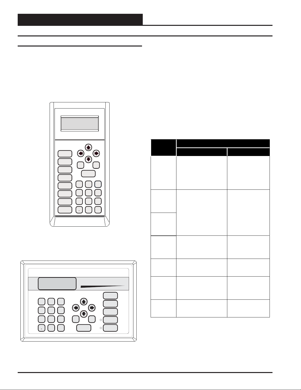
Modular Service Tool
2.02"
4.75”
Mode
Selection
STATUS
SETPOINTS
SCHEDULES
OVERRIDES
ALARMS
CONFIGURATION
BALANCE - TEST
ON
1.63"
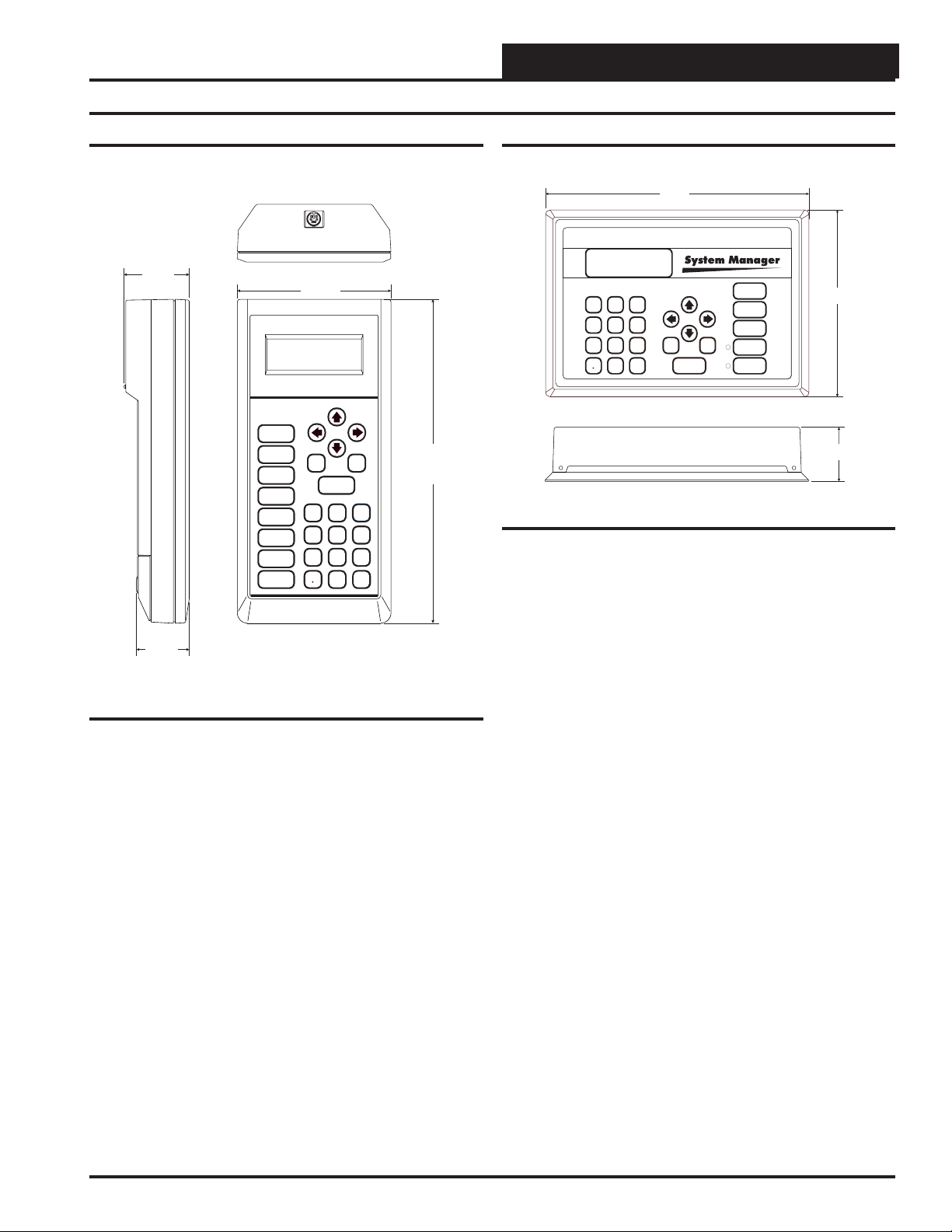
Figure 1: Modular Service Tool Dimensions
Description
The MUA II D Modular Service Tool is a system operator interface
that provides a direct link to enable the system operator to view the
status, configure and to adjust the setpoints of any controller on the
control system communications loop. The Service Tool is housed in
an attractive beige colored plastic enclosure. The display area is covered with a clear plastic bezel for protection of the display screen. The
Service T ool has a four line by 20 character display panel with adjustable contrast control and a 27 key membrane keypad for data selection
and entry. All keypad operations are simple and straight forward, utilizing non-cryptic plain English language messages. Menu driven programming allows for easy setup and operation without the need for
specialized training. The Wendy’s Modular Service Tool is supplied
with (4) AA (1.5V) Volt alkaline batteries a wall mount DC power
supply and a communication cable terminated with an 8 pin DIN connecter for connection to the Service T ool. The cable allows the user to
setup and program any MUA II D controller with a 8 pin DIN connector socket by simply plugging in the service tool to the socket on the
controller.
The Service Tool is designed to be carried by the system installer or
service technician. Its rugged plastic housing, provides superior protection for the electronic components housed inside. The MUA II D Modular
Service Tool is a top quality service tool that will stand up to the demands of the typical job site environment for many years.
UP
PREV
ESC
13
4
708
DEC
NEXT
DOWN
CLEAR
ENTER
2
5
6
9
MINUS
-
10.00”
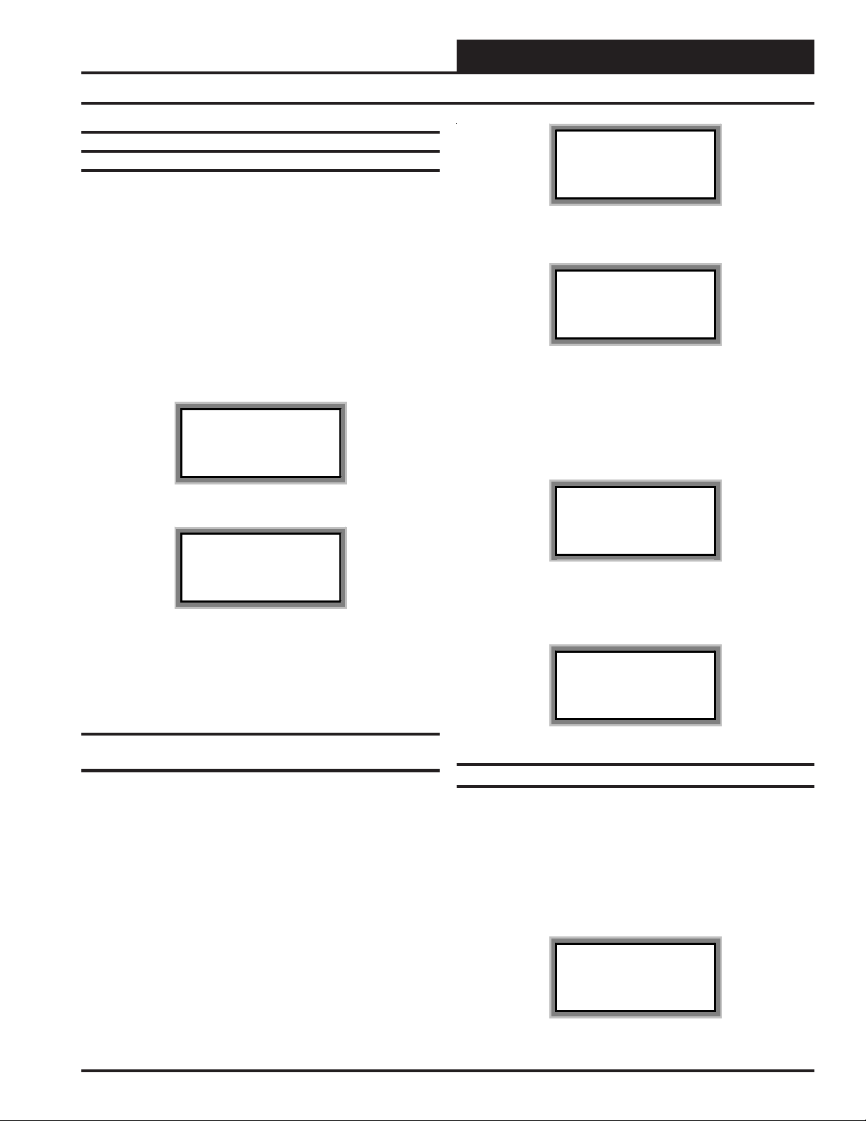
Modular System Manager
9.00"
13
2
5
6
4
708
9
DEC
MINUS
-
UP
PREV
ESC
DOWN
ENTER
Figure 2: Modular System Manager Dimensions
Description
The MUA II D Modular System Manager provides a direct link to enable the system operator to view the status and to adjust the setpoints of
any controller on the control system communications loop. The System
Manager is designed to be used with the MUA II D controllers. The
System Manager is housed in an attractive beige colored plastic enclosure. The System Manager is equipped with a four line by 20 character
backlighted display panel and a 24 key membrane keypad for data selection and entry. All keypad operations are simple and straight forward, utilizing non-cryptic plain English language messages. Menu
driven programming allows for easy setup and operation without the
need for specialized training. The System Manager also has 2 integral
LED’s for user notification of system alarm conditions and override
initiations. Protection from unauthorized users is provided by the System Manager’s integral multi-level passcode authorization programming.
On a Networked System the Modular System Manager is connected to
the communications and power loop of the system via modular cables
that simply plug into the System Manager board and the Power/Comm
Distribution Board. This virtually eliminates wiring errors and makes
installation fast and easy. When it is to be connected to a Stand Alone
system, a cable with modular connectors on one end and stripped wire
ends on the other end is provided to facilitate connecting communications and power to the System Manager from the 24 VAC power source
and the HVAC unit controller communication wiring terminals.
The System Manager is designed for wall mounting. Mounting holes
are provided to attach the System Manager to a standard handy box. It
is recommended that the System Manager be mounted at approximately
eye level to allow for ease of programming and reading of the display.
The System Manager is typically mounted in the building manager or
superintendent’s office or in an equipment room. The attractive enclosure is quite suitable for mounting in any location or with most decors.
STATUS
SETPOINTS
NEXT
SCHEDULES
CLEAR
OVERRIDES
ALARMS
6.25"
1.81"
Operator Interfaces 3
Page 4
Technical Guide
System Connections
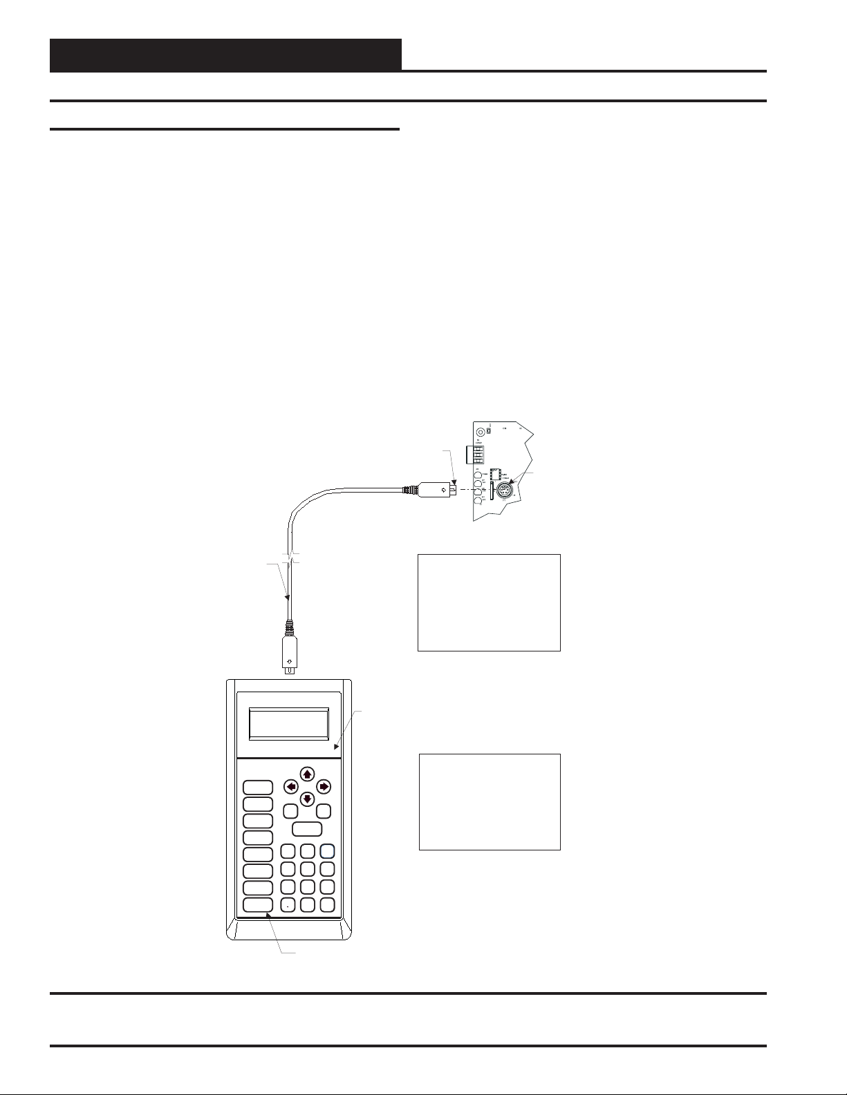
Modular Service Tool
Wether you have a Stand Alone, Interconnected or Networked Orion
Controls System, the Modular Service T ool always connects to an HV AC
unit controller via a prefabricated cable that is supplied with the service
tool. The Modular Service Tool cable is terminated on both ends with a
mini DIN connector. Attach one end to the Modular Service Tool and
the other end to the mini DIN connector on the HV AC unit controller. If
this is an Interconnected System, all controllers that are interconnected
Male DIN Connector
with communications cable can be programmed from any HVAC unit
controller on the loop. If this is a Networked System, all controllers on
the entire Networked System can be programmed from one HVAC unit
controller.
Be sure that the Modular Service Tool has fresh batteries installed or
that it is connected to a power source using the supplied power pack
before attempting any programming of the controller. See Figure 3 for
connection details.
Female DIN Connector
Connector Cable
Selection
SETPOINTS
SCHEDULES
OVERRIDES
CONFIGURATION
BALANCE - TEST
Mode
PREV
STATUS
13
ALARMS
4
708
DEC
ON
Typical Controller Board
The Modular Service Tool Can Be
Connected To The VAV/CAV
Controller Or The VAV/Zone
Controller By Plugging One End
Of The Supplied Cable Into the
Modular Service Tool DIN
Connector And The Other End
Into The DIN Connector On The
Controllers.
Modular Service Tool
UP
NEXT
DOWN
CLEAR
ESC
ENTER
2
5
6
9
MINUS
-
Be Sure The Modular Service
Tool Is Connected To The
Supplied Power Pack Or Has
Fresh Batteries Installed Before
Attempting Programming Of The
Controller. Be Sure The Power Is
Turned Off On The Modular
Service Tool Before Connecting
The Cable To The Controller.
Figure 3: Modular Service Tool
4
Power On Button
Operator Interfaces
Page 5
Technical Guide
U13
V62C518256L-70P
74HC573
CX8
RN1
YS101830PREV.
2PMODULARPSYSTEM
MANAGER
PCB80C552-5-16WPP442860=2/5
PDfD9722V7Y
R1
R4
24C128
74HC259
U14
CX9
470uF50v
1000uF10v
470uF50v
R12
R11
COMMOUT
COMMIN
74HC540
CX10
74HC923
82B715
RS-485P
V62C518256L-70P
75176
YS101830PREV.
2PMODULARPSYSTEM
PDfD9722V7Y
74HC259
470uF50v
1000uF10v
1000uF10v
COMMOUT
COMMIN
74HC540
CX14
82B715
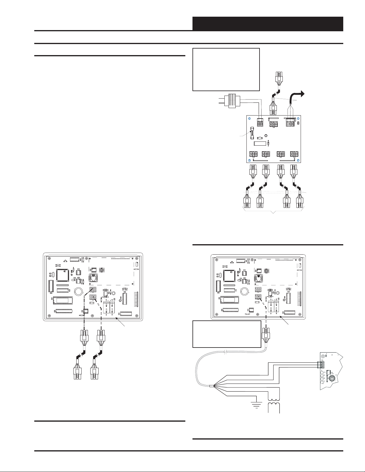
Modular System Manager
As previously described, when you are connecting the Modular System
Manager to a Networked System, the Modular System Manager is connected to the communications and power loop of the system via modular cables. These cables simply plug into the System Manager board
and to any device with modular connectors on any local loop on the
system. Devices with modular connectors include the Power/Comm Distribution Board, VAV/Zone controller and the Modular Polling device.
By using these plug in connections wiring errors are virtually eliminated and system installation is fast and easy. See Figure 4 for typical
connection information. See Figure 5 for typical Power/Comm board
wiring and connection information.
When the System Manager is to be connected to a Stand Alone system,
a 12 ft. cable with modular connectors on one end and stripped wire
ends on the other end is provided for this purpose. This is used to facilitate connecting communications and power wiring to the Modular System Manager from a 24 VAC power source and to the HVAC unit controller communication wiring terminals. See Figure 6 for wiring details. If the supplied cable wire is not long enough for your installation,
a standard modular cable of the correct length can be purchased through
WattMaster and one of the modular connectors can be cutoff to allow
for the transformer and communication terminal wiring connections. It
is recommended that you do not splice the communications wire if at all
possible. The transformer should be rated at 6 VA minimum power
output.
WARNING!
DO NOT GROUND THE 24V TRANSFORMER
THAT IS TO BE USED WITH THE
POWER/COMM BOARDS. GROUNDING OF
THE TRANSFORMER WILL DAMAGE THE
POWER/COMM BOARD AND ALL BOARDS
CONNECTED TO IT.A SEPARATE
TRANSFORMER MUST BE USED FOR EACH
POWER/COMMBOARD. NO EXCEPTIONS.
DO NOT CONNECT ANY OTHER DEVICES
TO THE TRANSFORMER USED FOR THE
POWER/COMM BOARD!
Line Voltage
24VAC
24VAC Transformer (By Others)
Size For Total Load Of Devices
Connected To Board
25
F1
4 Amp Slow Blow Fuse
4A
Power/ Cable To Power/Comm
Comm Other Distribution Board,
System Manager, MiniLink Or Other VAV/Zone Controllers
On Local Loop
Power/Comm Cable Power/Comm Distribution Board,
System Manager, MiniLink Or Other
VAV/Zone Controller On Local Loop. If This Is The First
Power/Comm Board On The Local Loop,
Connection Is Not Required.
TB2
VAC
24
LD1
POWER
V1
D1
P1
From Other
Polling Device
Connect To VAV/CAV Controller
If This Is First Power/Comm Board
On Local Loop - Otherwise No
Connection Is Required.
Local Loop RS-485
9600 Baud
All Comm Loop Wiring Is
Straight Thru
TtoT
C1
P5
RtoR
SHLD to SHLD
Local Loop RS-485
9600 Baud
COMMPIN
TB1
P2
SHLD
T
R
POWER& COMM
DIST.BOARD
YS101856
REV.0
R1
P4
P3
OUT
POWER& COMM
Polling Device
Figure 5: Typical Power/Comm Board Wiring
YS101830PREV.
2PMODULARPSYSTEM
MANAGER
U1
74HC259
CX2
U2
R3
R1
R4
PCB80C552-5-16WPP442860=2/5
PDfD9722V7Y
C1
X1
C2
U7
PAL
U8
CX7
CX11
U11
CX12
V62C518256L-70P
U12
R2
EWDOG
CX4
U3
R3
PHILIPS
24C128
U4
PHILIPS
CX5
CX6
R9
D3
C3
8583
X2
U6
RN1
74HC573
P1
CX8
P2
SC1
EPROM
VAR1
RAM
CX13
U13
75176
RS-485P
COMM
R14
Power/Commr Cables To
Power/Comm
Board, MiniLink Polling Device
Or VAV/Zone Controllers On
Local Loop.
DSPY1
U3
CX3
D1
R5
82B715
R6
D2
PJ1
COMMOUT
R11
R12
U9
9936
COMMIN
D6
MC34064A
R13
470uF50v
C7
470uF50v
All Modular Power/Comm
Cables Are To Be
WattMaster Part Number
PCC-xx Or PCCE-xx
Cables.
Distribution
RV1
R7
R10
D5
D4
L1
CX10
C4
74HC923
C5
U10
CX9
1000uF10v
C6
C8
1000uF10v
CX14
P3
74HC540
U14
Modular System Manager
Back of Front Cover
YS101830PREV.
2PMODULARPSYSTEM
MANAGER
U1
74HC259
CX2
U2
R3
R1
R4
PCB80C552-5-16WPP442860=2/5PDfD9722V7Y
C1
X1
C2
U7
PAL
U8
CX7
CX11
U11
CX12
V62C518256L-70P
U12
Note: If Desired A Power/Comm Board As
Used With The Networked System Can
Be Installed And Wired Instead Of Using
The Pigtail Cable Wiring Shown Below.
See The Networked System Wiring
Diagram For Details.
Use Supplied Modular
Cable With Stripped Ends
For Connection To Terminal
Block And Transformer
WHITE (T)
DRAIN WIRE (SHLD)
BLACK (R)
RED (24 VAC)
BROWN (GND)
GREEN (GND)
R2
EWDOG
CX4
U3
R3
PHILIPS
24C128
U4
PHILIPS
CX5
CX6
R9
D3
C3
8583
X2
U6
RN1
CX8
74HC573
SC1
EPROM
RAM
CX13
75176
RS-485P
COMM
R14
DSPY1
U3
CX3
D1
R5
82B715
R6
D2
PJ1
COMMOUT
P1
P2
VAR1
U13
D5
R11
R12
L1
U9
C4
9936
COMMIN
D6
MC34064A
R13
CX9
1000uF10v
470uF50v
C8
C7
1000uF10v
470uF50v
RV1
R7
R10
D4
CX10
74HC923
C5
U10
C6
P3
74HC540
CX14
U14
Modular System Manager
Back of Front Cover
T
SHLD
R
Controller Board
Figure 4: Modular System Manager - Networked
Operator Interfaces
Class 2 Transformer
Rated For 6 VA Minimum
Figure 6: Modular System Manager - Stand Alone
5
Page 6
Technical Guide
General Programming Information
Operator Interfaces Comparison
In order to configure and program the Orion System controllers you
must have a central operators interface or a personal computer with the
Prism computer front end software installed. Two different central operators interfaces are available for programming of the Orion Controls
System. Y ou may use either the Modular Service Tool and/or the Modu-
lar System Manager to access the status and setpoints of any controller on your communications loop.
Mode
Selection
STATUS
SETPOINTS
SCHEDULES
OVERRIDES
ALARMS
CONFIGURATION
BALANCE - TEST
ON
Modular Service Tool
13
2
MINUS
PREV
6
9
-
4
708
DEC
5
UP
ENTER
DOWN
NEXT
CLEAR
2
5
6
9
MINUS
-
PREV
ESC
13
4
708
DEC
System Manager
UP
NEXT
DOWN
ENTER
CLEAR
ESC
STATUS
SETPOINTS
SCHEDULES
OVERRIDES
ALARMS
The Modular Service Tool or the System Manager allow the user to
view any temperature or output condition and change any setpoint to
fine tune the operations of the total system. All keypad operations are
simple and straightforward, utilizing non-cryptic plain English messages.
Display Screens & Data Entry Keys
The System Manager display screens and the Modular Service Tool
display screens are very similar. For most setpoints and modes the only
difference between using the Service T ool and the System Manager is a
few differences in the function of the keypads. The Modular Service
Tool has 2 extra function keys (“Configuration” and “Balance-Test”)
that are not available on the System Manager. Where a dif ference in the
keypad input or the screens displayed exists between the two operators
interfaces, both screens or keypads will be shown. See the chart below
for a list of the keypad descriptions and functions.
Keypad
Description
ESC
ENTER
Clear
Minus
DEC
⇐ ⇒
⇑
⇓
System Manager Modular Service Tool
Used to exit from screens
or from data entry. Use
this s creen to return to the
main menu from any
screen in the system
This key is used to close a
data entry field and
advance to the next item
or screen
If a data entry mistake is
made, press this key to
clear the data entry field
and start over
If the a setpo i nt with a
negative value is required,
press this key for the
minus sign
Press this key when
entering data that requires
a decim al po int
Ste p s the user to the nex t
controller on the loop on
interconnected or
networked systems
Steps the user backward or
forward th rou gh the
screens
Key Function
Same function as
System Manager but
also turns off the
power to the Se rvic e
Tool when on the
main menu screen
Same function as
System M an age r
Same function as
System M an age r
Same function as
System M an age r
Same function as
System M an age r
Same function as
System M an age r
Same function as
System M an age r
6
Modular System Manager
Operator Interfaces
Page 7
Modular System Manager
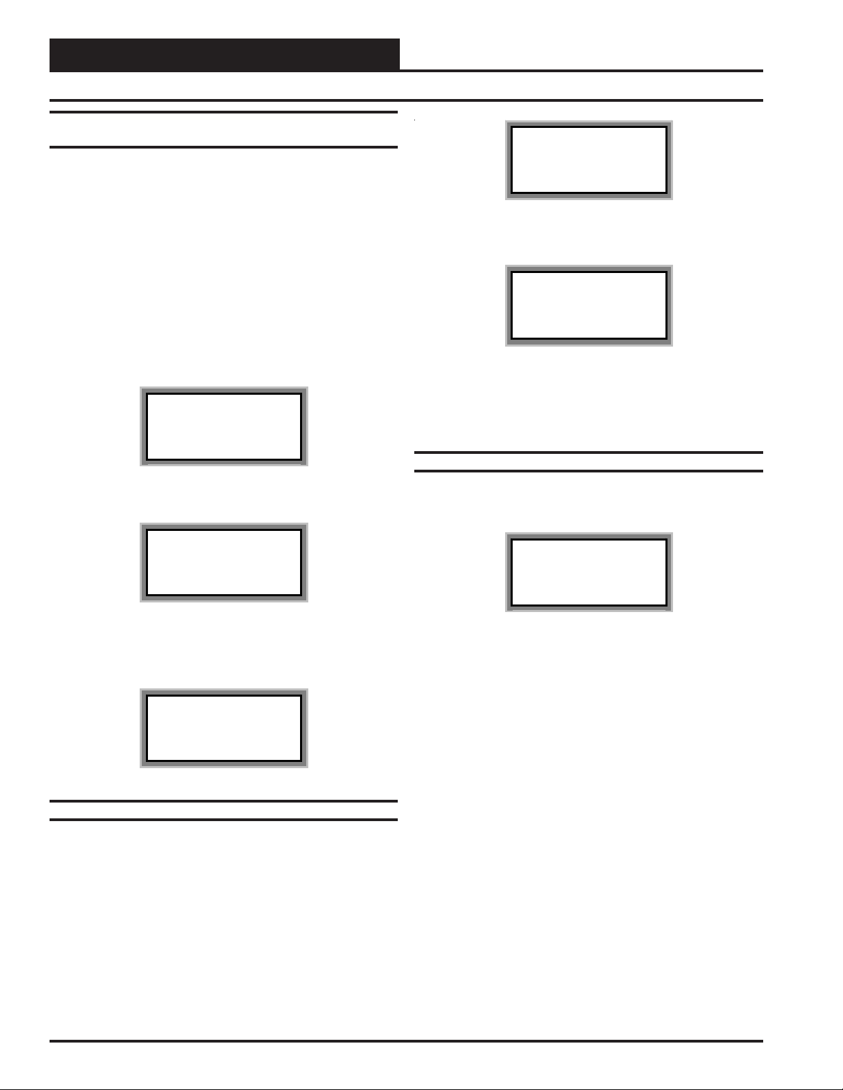
System Manager Initialization Screens
When the System Manager is powered up, the first screen displays the
current version of the software installed in your System Manager and
whether your system is configured for Network or Stand-Alone operation. The System Manager will try to detect the type of installation you
have by scanning the communications loop. See the screens below. If it
is configured for Stand-Alone operation, only the HVAC unit controller
that the System Manger is connected to is available for programming.
On a Networked System, all controllers on the communications loop
are available for programming by entering their loop address (ID). If an
Interconnected System is connected to the System Manager all controllers that are connected to the communication loop are available for programming.
Initializing
System Manager vX.XX
Wattmaster Controls
Network Mode
Technical Guide
1) Set Time & Date
2) Communications
->) Next Menu
ESC) Exit Menu
Press the “2” key on the keypad to enter the communications screen.
THIS ACTION REQUIRES
PASSCODE CLEARANCE
Enter Passcode: xxxx
Enter the seven digit passcode “2337377” to access the next screen.
These seven digits spell the word “ADDRESS” on your telephone keypad if you forget what they are. Once on the screen shown below, use
the keypad to enter the correct mode for your installation. The screen
will now show “Stand Alone System” or “Multiple MGRS” or “Network System” depending on what you selected.
System Manager vX.XX
Monday Operations
09/09/99 04:26 PM
Outdoor Air 87°F
The screen above will appear a few seconds later. If this is a Stand
Alone system, the outdoor air temperature will not be shown on the
display. If you believe your system is incorrectly configured, please follow the instructions that follow. If your system is configured correctly
proceed to the Menu Screens section of this manual.
Configuring The System Manager For Network
Or Stand-Alone Operation
The System Manager can operate as a Stand Alone interface with the
HVAC unit controller and does not require any other communications
devices to read or reset any available values. T o verify if it is currently
configured for Stand Alone operation, cycle power to the System Manager and monitor the LCD initialization screen. If it is configured for
Stand Alone you will see the words “Stand Alone Mode” on the bottom
line of the display. If you are using this System Manager on a communications loop and have installed a MiniLink or CommLink II communications interface, then you need to operate in Network Mode and the
bottom line should display the words “Network Mode”.
If your display indicates a different mode than the one you need, press
the “Enter” key and the following screen will appear.
0) Stand Alone
1-60) Multiple MGRS
63) Network System
Enter Mode Of Op:.xx
Once you have the correct mode displayed, press the ENTER key. The
following screen will appear to telling you that you have changed the
system mode. Press any key on the keyboard to exit this screen.
You Have Changed The
System Mode
Press Any Key To
Continue
Modular Service Tool
The Modular Service Tool is very similar to the System Manager in its
operations as stated previously . Two exceptions to this are that the Service Tool unlike the System Manager does not check the system to determine whether it should be in Network or Stand Alone Mode and it
does not have any passcoding capability.
After connecting the Service Tool to the controller with the supplied
cable, press the “On” key. The following screen will appear.
Service Tool vX.XX
Monday Operations
09/09/02 04:26 PM
Stand Alone Mode
Operator Interfaces
7
Page 8
Technical Guide
General Programming Information
Configuring The Modular Service Tool For
Network Or Stand-Alone Operation
As with the System Manager described previously, you must determine
if the mode displayed is correct for your system. If it is configured for
Stand Alone you will see the words “Stand Alone Mode” on the bottom
line of the display. This is the factory default setting. If you are using
this tool on a system or controller that does not have a CommLink or
MiniLink installed, then this is the correct setting and you can proceed
to desired screen by pressing the menu key or any function key. If you
are using this Service Tool on a communications loop with and have
installed a MiniLink or CommLink II communications interface, then
you need to operate in network mode and the bottom line should display the words “Network Mode”.
If your display indicates a different mode than the one you need, press
the "Enter" key and the following screen will appear.
1) Set Time & Date
2) Communications
3) Energy Saving
ESC) Exit Menu
1) Set Time & Date
2) Communications
3) Energy Saving
ESC) Exit Menu
When this screen appears press the “3” key to access the Energy Saving
screen. The following screen will appear.
Energy Saving
Automatic Power Down
Minutes: xx
Press ESC to Exit
Enter the number of minutes you want the Service Tool to stay active
before it automatically powers down. To cancel the automatic power
down enter “99”. After you have entered this number between 1 and 99
minutes, press “ESC” to exit as the screen instructs you.
Unit Selection
Press the “2” key on the keypad to enter the communications screen.
0) Stand Alone
1) Network System
Enter Mode Of Op:.xx
As the screen indicates, press “0” or “1” keys to select the proper
mode of operation. When you are finished press “Enter” to move
back to the main menu screen.
You Have Changed The
System Mode
Press Any Key To
Continue
Setting The Energy Saving Timer
The Modular Service Tool has a built in timer that can be programmed
to shut the Service T ool off after a specified period of time if no buttons
are pressed. This is a very useful feature if you are powering the Service
Tool from the internal batteries. To access this setting from the main
status screen press "Enter".
With both the Modular Service Tool and the Modular System Manager
You must enter the ID (Address) of the controller you wish to program
Unit Selection
Enter Unit ID#
Selected ID#: xxxx
With the main menu screen displayed, press the function key associated
with the operation (setpoints, configuration, etc.) you want to perform.
The screen shown above will appear asking you to enter a unit I.D.#
(controller address). Put in the ID# of the controller you wish to communicate with then press the “ENTER” key.
If this is Network System (the system has a CommLink), the Unit ID is
actually two separate numbers, combined into one value. The first part
of the number contains the Loop Address at which the controller is
located. The second part of the number contains the actual controller
address. See Examples #1 & #2 below.
If this is a Stand Alone System (system without a CommLink) this will
be a number between 1 and 59. It is recommended the address be set to
1. See example #3 below.
EXAMPLE #1
You would like to view the 3rd controller on the 5th loop. Enter “503”
as the Unit ID.
8
Operator Interfaces
Page 9

Technical Guide
EXAMPLE #2
Y ou would like to view the 12th controller on the 24th loop. Enter “2412”
as the Unit ID
EXAMPLE #3
You would like to view the only controller on the loop. Enter 1 as the
Unit ID. No loop number is required since there is only one loop.
Hit the “Enter” key after entering the unit ID. If you are using the Modular
Service T ool you will be taken directly to the first screen for the operation you are trying to program.
System Manager Passcodes
Anytime you enter a unit ID with the Modular System Manager you
will be asked for a passcode. Passcodes are not required to view Status
Screens. The screen below will appear if this action requires passcode
clearance.
THIS ACTION REQUIRES
PASSCODE CLEARANCE
Enter Passcode: xxxx
The System Manager has two levels of user access. Level 1 users are
limited to viewing or changing the Time and Date and Operating Schedules. Level 2 users have complete system access. Any status or setpoint
field can be read or reset from the System Manager.
These two levels of passcodes are programmable by any Level 2 user.
The default Level 1 passcode is “111 1” and the default Level 2 passcode
is “2222.”
If you wish to change either Level 1 or Level 2 passcodes please see the
instructions that follow.
From the main status screen press "Enter", The following screen will
appear.
1) Set Time & Date
2) Communications
->) Next Menu
ESC) Exit Menu
Press ">", to proceed to the next menu and the following screen will
appear.
1) Change Passcodes
2) Loop Search
<-) Prev. Menu
ESC) Exit Menu
Press the “1” key on the keypad to enter the Change Passcode screen.
THIS ACTION REQUIRES
PASSCODE CLEARANCE
Enter Passcode: xxxx
Enter the default Level 2 passcode “2222” to access the next screen.
You must use the Level 2 passcode to change passcodes. Level 1
passcodes will not allow changing passcodes!
Enter New Passcode
Level 1.....: xxxx
Level 2.....: xxxx
[Must Be 4 Digits]
Operator Interfaces
This screen allows you to enter new Level 1 or Level 2 passcodes. The
actual digits in your passcodes are never displayed. An “X” is used as a
place holder for each digit entered. Passcodes must always be four digits in length, so the usable range of numbers is 1000 to 9999.
Caution: If you change the Level 2 passcode and cannot
remember what it is, you will be locked out of
your system!
9
Page 10

Technical Guide
General Programming Information
Scheduling
The MUA II D controller scheduling screens are accessed by pressing
the “Schedule” button on either the System Manager or the Modular
Service T ool. Press the number button for the scheduling function you
wish to view.
1)Schedule Overrides
2)Week Schedules
3)Holidays
ESC) Exit Menu
Week Schedules
Event #1
MUA II Sched ID 59
Sunday Event #1
Start Time : xxxx
Stop Time : xxxx
Event #2
Note: The second line displays which day of the week is cur-
rently being programmed. This automatically increments
as you finish the Event #2 screen and continue to the
next days Event #1 screen.
Caution: The controller ships with all schedules set to zero so
that the controller will not attempt to heat or cool
before the user has configured his system.
Holiday Start/Stop Day Selection
MUA II Hldy ID 59
Holiday # 1
Start Mon/Day: xxxx
[ July 4
MUA II Hldy ID 59
Holiday # 1
Stop Mon/Day: xxxx
[ July 4
th
= 704 ]
th
= 704 ]
MUA II Sched ID 59
Sunday Event #2
Start Time : xxxx
Stop Time : xxxx
If you are using the internal scheduling capability of the V AV/CA V controller, set the schedule hours and holiday periods from the menu shown
above. You can also force the unit to operate continuously in occupied
or unoccupied mode by selecting the Schedule Override menu item and
entering the desired command.
If you are using an external contact closure to signal the occupied mode,
you must access the Week Schedule screens and set all start and stop
times to zero to prevent the internal schedule from bringing the equipment on when you don’t want it to operate.
The screens will step through the Start T ime and then the S top T ime for
each day of the week. You can quit at any point in the process by pressing the “Escape” key. There are two Start/Stop events available per day
so the screen will show which event is being programmed. If you need
only one event, leave Event #2 times to ZERO.
All times are in 24-hour military format, so 5:00 PM would be entered
as 1700.
If both the Start and Stop T imes are ZERO, the schedule is in a continuous OFF mode. (Use for Remote Signal Contact)
The screens will step through the fourteen possible holidays, one period at a time. Line 2 shows which holiday is currently being programmed. Since a holiday period can encompass more than one day,
you need to program the day the holiday starts and the day the holiday
ends. If your holiday only lasts one day simply set both the Start Day
and the Stop Day to the same value. Remember to combine the month
and day into a single four-digit value.
EXAMPLE: 704 = July 4th (Note : Leading zero not required)
1225 = December 25
th
Holiday Start/Stop Times
MUA II Hldy ID 59
Holiday Schedule
Start Event #1: xxxx
Stop Event #1: xxxx
MUA II Hldy ID 59
Holiday Schedule
Start Event #2: xxxx
Stop Event #2: xxxx
If both the Start and Stop Times are 2359, the schedule is in a continuous ON mode.
10
The fourteen holidays all use the same Start and Stop times which are
entered on this screen and then next. It is entered in 24-hour military
format, the same as a regular week schedule.
Operator Interfaces
Page 11

Technical Guide
Normally the holidays will operate in an unoccupied mode or a reduced
schedule mode. There are two start/stop events available on holidays to
match the standard schedule number of events.
Schedule Override
Schedule Override
Enter Override : x
[0=Auto 1=ON 2=OFF]
If you want to force the unit to operate in a continuous Occupied or
Unoccupied mode, select this menu item to activate the desired method.
If a Schedule Override is active, all other methods of schedule control
are ignored. (Push-Button, Internal or Remote)
As you can see on the last line of the display you enter a ‘1’ to run
continuously in the Occupied Mode or a ‘2’ to run continuously in the
Unoccupied Mode.
T o restore normal schedule operations, make sure a ‘0’ is entered here.
This override remains in effect until canceled by the user and does not
time-out like the Output Overrides do after 10 minutes of no communications.
For the Service T ool, from the main screen press “Enter” and the fol-
lowing screen will appear.
1) Set Time & Date
2) Communications
3) Energy Saving
ESC) Exit Menu
Press 1 to enter the Set Time and Date Menu.
Programming Times
Although the times are displayed on the Main Screen in a standard 12hour format, they are programmed using the 24-hour military format. If
the VAV/CA V controller was configured to use its own Internal Schedules, the Occupied/Unoccupied modes are calculated on the basis of the
current real time clock reading.
Program Time/Date
Day (Sunday=0): x
Enter Hr. (0-23): xx
Enter Minutes : xx
Note: Do not use the Force OFF mode in place of setting all
the week schedules to ZERO if you are using a Remote
Signal for your scheduling since the Override has priority over the Remote Signal.
Setting Time & Date
Both the Modular Service Tool and Modular System Manager are
equipped with a real time clock chip allowing it to maintain the correct time. Once the correct time and date are entered, the information
is broadcast globally to all controllers on the entire system. The System Manager will also broadcast this information once every day at
midnight to synchronize all the controllers on the system.
From the main System Manager screen press “Enter” and the following screen will appear.
1) Set Time & Date
2) Communications
->) Next Menu
ESC) Exit Menu
Press 1 to enter the Set Time and Date Menu.
Day Enter the Day of the Week (0 to 6)
Sunday = 0
Hours (Hr) Enter Hours in 24-Hour Military Format
(1700 = 5:00 PM)
Minutes - Enter the Minutes
(0 to 59)
Programming Date
Program Time/Date
Month (1-12): xx
Day (1-31): xx
Year (00-99): xx
Month Enter the Month (1 to 12)
Day Enter the Day of the Month (1 to 31)
Year Enter the current Year with two digits (00 to 99)
Space Sensor Overrides
When a space sensor with override option is used the System Manager
or Modular Service Tool can determine and report any units which are
currently operating in an override condition. This function requires that
a polling device is installed on the loop where the controllers are located.
Operator Interfaces
T o access the Space Sensor Overrides screen, press the “Override” button located on the System Manager or Modular Service Tool. A screen
will appear asking you to enter a unit ID. Enter an ID for any active
11
Page 12

Technical Guide
General Programming Information
controller on the system and press "Enter". The following screen will
appear.
Overrides Screen
SEARCHING!
After the System Manager or Modular Service T ool completes its search,
it will list the first unit on the system that is currently in the override
mode. Press the previous or next button to scroll through all units that
are in the Override Mode.
Overrides Screen
Loop = 1 Unit = 59
Override Unit
Alarm Search
The System Manager or the Modular Service T ool can be used to search
for all active alarms on the system. From either of the operators interfaces press the “Alarm” key. The Unit Selection screen below will be
displayed. Enter the Unit ID of any unit on the system and press “Enter”.
The following screen will appear. The operators interface will search
for any active alarms on the entire system.
Alarm Screen
SEARCHING!
After the System Manager or Modular Service T ool completes it’s search,
it will list the first unit on the system that currently has an active alarm.
Press “Enter” to scroll through all the alarms on that particular unit. T o
move to the next unit or back to the previous unit use the “Prev” or
“Next” arrows to move between units with alarms.
Alarm Search Screen
Loop = 1 Unit = 59
Space Sensor Failure
T o clear any alarms that are found you must fix the problem indicated in
the alarm. Once the problem is fixed, the alarm will clear from the screen
the next time the unit is polled.
Unit Selection
Enter Unit ID#
Selected ID#: xxxx
12
Operator Interfaces
Page 13

Programming The MUA II D Controller
Technical Guide
Configuration
In order to correctly setup the MUA II D controller you must first configure several parameters in regard to the type of HV AC unit and system
you have installed. Most of these values and operating parameters are
only set once, at the initial system setup and are never changed.
System Manager Instructions
From any menu screen press the “Setpoint” key. The unit selection screen
will appear requesting that you enter the unit ID number. Enter the cor rect unit ID number of the MUA II D controller you want to configure
and hit the “Enter” key. You will see the screen shown below.
1)Change Setpoint
2)Configure Unit
3)Damper Force
ESC) Exit Menu
Press “2” on the keypad to enter Configuration Screen #1.
Modular Service Tool Instructions
From any menu screen press the “Configuration” key. The unit selection screen will appear requesting that you enter the unit ID number.
Enter the correct unit ID number of the MUA II D controller you want
to configure and hit the “Enter” key. You will then see unit configuration screen #1.
Configuration Screen #1
MUA II Cnfg IDxxxx
Proof Of Flow Switch
Installed: NO
(0=No 1=Yes)
If you need proof of airflow before allowing any heating or cooling
stages to operate, install a differential pressure switch with a contact
closure that is connected to analog input #7 and select this option. If
this option is not selected, the air handler assumes there is adequate
airflow anytime the fan is running and ignores this signal defaulting
input #7 to space humidity.
Configuration Screen #2
temperatures for control of the HVAC unit, the setting should be set to
0=No. If you have an Outside Air Humidity Sensor installed and wish
to use dewpoint calculations for unit control, select 1=Y es. If you have
a sensor installed and do not select 1=Yes, the sensor readings will be
ignored.
Configuration Screen #3
MUA II Cnfg IDxxxx
Heat In Dehumidify
Installed : Yes
(0=No 1=Yes)
If you need to allow heat during dehumidification, select this option. If
this option is not selected, the controller assumes that only reheat will
be allowed during dehumidification mode.
Configuration Screen #4
MUA II Cnfg IDxxxx
Is External Heat
Reverse Actn: Yes
Use Left/Right Arrow
If you need the modulation of the external heat to be reverse acting,
select this option. If this option is not selected, the controller assumes
the modulation will be direct acting.
Configuration Screen #5
MUA II Cnfg IDxxxx
If External Heat
Output Range.: 0
(0=2-10V 1=0-10V)
If you have an external heat device to be controlled by the MUA II D
controller, you can select between the voltage ranges that will be used
to control the device. The available options are 2-10 VDC and 0-10
VDC.
Configuration Screen #6
MUA II Cnfg IDxxxx
OA Humidity Sensor
Installed: NO
(0=No 1=Yes)
This configuration screen allows the user to indicate whether an Outside Air Humidity Sensor is to be installed and used to calculate
dewpoint settings. If you either don’t have an Outside Air Humidity
Sensor installed or have one installed but wish to use only drybulb
Operator Interfaces
MUA II Cnfg IDxxxx
Broadcast Outside
Temperature:_NO
(0=No 1=Yes)
If you have other unit controllers on the system, you can elect to broadcast the Outside Air Temperature to these units by selecting 1=Yes on
this screen. If you don’t have other controllers or they have their own
Outside Air Temperature Sensors, select 0=No on this screen.
13
Page 14

Technical Guide
Programming The MUA II D Controller
Configuration Screen #7
MUA II Cnfg IDxxxx
Broadcast Humidity
Reading :_NO
[0=No 1=Yes]
If you have other unit controllers on the system, you can elect to broadcast the Outside Humidity to these units by selecting 1=Yes on this
screen. If you don’t have other controllers or they have their own Outside Humidity Sensors, select 0=No on this screen.
Configuration Screen #8- #27
MUA II Cnfg IDxxxx
Stage Configurations
Rly #xx: Not Used
Select Using ‘0’ Key
The first relay on the controller is always reserved for the Supply Fan.
The remaining four relays on the main board and the additional 16 relays on the expansion relay modules can be configured by pressing the
left or right arrow key to change the relay to the desired configuration.
Press “1” on the keypad to enter the first unit setpoint screen.
Modular Service Tool Instructions
From any menu screen press the “Setpoint” key. The unit selection screen
will appear requesting that you enter the unit ID number. Enter the cor rect unit ID number of the MUA II D controller you want to change
setpoints and press the “Enter” key. You will then see setpoint screen
#1.
Setpoint Screen #1
MUA II Spts IDxxxx
Supply Air Temp
Setpoint.....: xxx°F
The Supply Air Setpoint is the desired temperature to be delivered by
the MUA II D at any time during the occupied mode of operation
Description Minimum De fault Maximum
Supply Air Temp Setpoint 50° F 70° F 90° F
Setpoint Screen #2
Possible Relay Descriptions:
Not Used
HeatStage
CoolStage
Gas Reheat
External Heat
The MUA II D controller does not require whether you start configuring your heating or cooling stages first nor does it require that you utilize consecutive relays until all heating or cooling stages have been
defined. This method allows the greatest flexibility in the field, but it
requires close attention to the wiring of the heating and cooling stages
to prevent incorrect and possibly harmful operation. The controller assumes that there will only be one relay configured for Hot Gas Reheat
and one relay for External Heat Enable, although it doesn’t prevent
multiple relays from being selected.
Setpoints
System Manager Instructions
From any menu screen press the “Setpoint” key. The unit selection screen
will appear requesting that you enter the unit ID number. Enter the cor rect unit ID number of the MUA II D controller you want to change
setpoints for and hit the “Enter” key. You will see the screen shown
below.
MUA II Spts IDxxxx
Staging Deadbands
Cooling....: xxx°F
Heating....: xxx°F
The Cooling Deadband added to the Supply Air Setpoint gives the
Cooling Mode Setpoint. When the Outside Air T emperature rises above
this setpoint, the MUA II D will go to Cooling Mode. The Heating
Deadband subtracted to the Supply Air Setpoint gives the Heating
Mode Setpoint. When the Outside Air Temperature drops below this
setpoint, the MUA II D will go to Heating Mode.
Description Minimum Default Maximum
Cooling Deadband 2° F 5° F 20° F
Hea ting D ead ban d 2° F 5° F 20° F
Setpoint Screen #3
MUA II Spts IDxxxx
Unoccupied Deadbands
Cooling....: xxx°F
Heating....: xxx°F
14
1)Change Setpoint
2)Configure Unit
3)Damper Force
ESC) Exit Menu
The Uncoccupied Cooling Deadband added to the Supply Air Setpoint
gives the Unoccupied Cooling Mode Setpoint. When the Space Air
Temperature rises above this setpoint, the MUA II D will go to Unoccupied Cooling Mode. The Unoccupied Heating Deadband subtracted
Operator Interfaces
Page 15

Technical Guide
from the Supply Air Setpoint gives the Unoccupied Heating Mode
Setpoint. When the Space Air T emperature drops below this setpoint,
the MUA II D will go to Unoccupied Heating Mode.
If the default setpoint of 30° F is used it will cancel the corresponding
unoccupied cooling or unoccupied heating mode.
Descriptio n Minimum Default Maximum
Unoccupied Cooling
Deadband
Unoccupied Heating
Deadband
Cooling
Deadband
Setpoint
Heatling
Deadband
Setpoint
30° F 30° F
30° F 30° F
Setpoint Screen #4
MUA II Spts IDxxxx
Systems With Re-heat
Dewpoint Control
Setpoint...: xxx°F
The systems capable of dehumidification will enter this mode of operation when the Outside Air Dewpoint rises above the Dewpoint Setpoint.
Description Minimum Default Maximum
Dewpoint Setpoint 40° F 55° F 80° F
Setpoint Screen #5
Setpoint Screen #6
MUA II Spts IDxxxx
Heat Delay During
Dehumidifcation
Will Occur..: xxxMin
If heating during dehumidification is configured, this is the amount of
time the heating call will be delayed after the dehumidification is activated.
Description Minimum Default Maximum
Heat Delay 0 Min 2 Min 10 Min
Setpoint Screen #7
MUA II Spts IDxxxx
Alarm Limits
Hi SAT Limit.: xxx°F
Lo SAT Limit.: xxx°F
If the Supply Air Temperature ever rises above the Hi SAT Limit or
drops below the Lo SAT Limit for a user defined period of time, an
alarm is generated.
Description Minimum Default Maximum
Hi SA T Limit 50° F 150° F 150 ° F
Lo SAT Limit 0° F 0° F 70° F
MUA II Spts IDxxxx
Enthalpy Staging
Deadband....: xxxBTU
Hysterisis..: x.xBTU
The Enthalpy Deadband if the amount Enthalpy in the Outside Air
needed to activate an extra stage of cooling. The Enthalpy Hysterisis
is use to avoid unnecessary cycling of the cooling stages when the Out-
side Enthalpy is close to the setpoint.
Description Minimum Default Maximum
Enthalpy Deadband 3 BTU 5 BTU 20 BTU
Entha lpy Hysterisis 0.5 BT U 1 BTU 2.5 BTU
Setpoint Screen #8
MUA II Spts IDxxxx
Supply Air Alarms If
Out Of Range For
xxx Minutes
This is the amount of time the Supply Air Temperature must be outside
either the Hi or Lo SAT Limit setpoint before it generates an alarm.
Description Minimum Default Maximum
Min utes 0 Min 30 Min 300 M in
Operator Interfaces
15
Page 16

Technical Guide
Programming The MUA II D Controller
Setpoint Screen #9
MUA II Spts IDxxxx
Set Sat Temp Reset
SPC= xxx Spt= xxx
SPC= xxx Rst= xxx
A Type III Thermistor Sensor connected to AIN 1 can be used to reset
the Supply Air Temperature. This screen allows the user to set the temperature that the reset will begin at and the new reset Supply Air Temperature range.
Description Minimum Default Maximum
Minim um Range 40° F 0° F 100° F
Maxim um R a nge 40° F 0° F 100° F
Reset SAT S pt SAT Spt Spt + 50° F
Setpoint Screen #10
MUA II Spts IDxxxx
Set Dewpoint Reset
HUM= xxx Spt= xxx
HUM= xxx Rst= xxx
An Indoor Humidity Sensor connected to AIN7 can be used to reset the
Dewpoint Setpoint. This screen allows the user to set the relative humidity percentage that the reset will begin at, and the new reset Dewpoint
Setpoint percentage range.
Description Minimum Default Maximum
Minimum Range 0% 0% 100%
Maximum Range 0% 0% 100%
Reset 35° F 55° F Dewpoint Spt
MUA II Spts IDxxxx
Heating Stage Delays
Staging Up : xx Min
Staging Down: xx Min
MUA II Spts IDxxxx
Heating Stage Delays
Min Run Time: xx Min
Min Off Time: xx Min
Both the Heating Stages and the DX Cooling Stages utilize S taging Up
and Down delay periods between stages and Minimum Run T imes and
Off Times.
Both modes have their own set of staging and run delay times. The
Heating timer screens look exactly the same as the cooling except they
reference the Heating instead of Cooling.
See the Sequence of Operation Manual for information on how these
delays and run times are used.
Description Minimum Default Maximum
Cooling Stage U p 3 Min 3 Min 15 Min
Cooling Stage Down 1 Min 1 Min 15 Min
Cooling Min R un T ime 5 M in 5 Min 15 Min
Cooling Min Off Time 3 Min 3 Min 15 Min
Heating Stage U p 3 Min 3 Min 15 Min
Heating Stage Down 1 Min 1 Min 15 Min
Heating Min Run Time 2 Min 2 Min 15 Min
Heating Min Off Time 1 Min 1 Min 15 Min
Setpoint Screen #11-14
MUA II Spts IDxxxx
Cooling Stage Delays
Staging Up : xx Min
Staging Down: xx Min
MUA II Spts IDxxxx
Cooling Stage Delays
Min Run Time: xx Min
Min Off Time: xx Min
16
Setpoint Screen #15
MUA II Spts IDxxxx
External Mod Heat
DeadBand.....: xxx°F
The External Heat Pr oportional deadband is the range through which
the external heating device will proportionally modulate.
Description Minimum Default Maximum
Proportional Band 1° F 5° F 30° F
Operator Interfaces
Page 17

Technical Guide
Setpoint Screen #16
MUA II Spts IDxxxx
Push-Button Override
Duration : x.x Hr
If the Space T emperature sensor contains the optional push-button override then this is the amount of time the unit will revert to occupied
operation whenever the button is pressed during the unoccupied mode.
Description Minimum Default Maximum
Dura tion 0.0 Hr 2.0 Hr 8.0 Hr
Setpoint Screen #17
MUA II Spts IDxxxx
Maximum Slide Offset
Effect on Spt: x°F
If Space Temperature is used as the controlling sensor for the HVAC
unit and it is supplied with the optional Setpoint Slide Adjust, this is
the maximum amount the user can adjust the heating and cooling setpoints up or down as the slide is moved from the center position to its
full up or down position.
Description Minimum Default Maximum
Effect on Spt
F0° F10° F
0°
Setpoint Screen #18
MUA II Spts IDxxxx
AHU Scheduled By
Schedule Number: x
0=AHU 1-7=Scheduler
Setpoint Screen #19
MUA II Spts IDxxxx
Fan Time Delay
Before Activation
Can Occur..:XXX Sec
This is the time delay that occurs before the fan is activated when the
unit switches into the occupied mode from unoccupied mode.
Description Minimum Default Maximum
Fan Time Delay Before
1 Secon d 60 Seco nd 180 Se c on d
Activatio n Can O c cur
Setpoint Screen #20
MUA II Spts IDxxxx
Sensor Calibration
SAT: xx.x° xx.x
OAT: xx.x° xx.x
The Thermistor Type III temperature sensors connected to the MUA II
D controller can be calibrated using this screen. Enter a Positive value
to increase a reading and a Negative value to decrease a reading.
Description Minimum Default Maximum
Supply Sensor - SAT -100.0° F 0.0° F +100.0° F
Outdoor Sensor - OAT -100.0° F 0.0° F +100.0° F
°
°
Setpoint Screen #21
MUA II Spts IDxxxx
Sensor Calibration
Reset Sensor
SPC: xx.x° xx.x
°
Normally, the MUA II D controller will use its own internal time clock
and week schedules to set the occupied mode of operation. If you have
several air handlers you can connect an external scheduling device to
the communications loop and program the air handler for the desired
schedule to follow. If the MUA II D controller is using its internal schedule, enter a ‘0’ for the Schedule Number.
Description Minimum Default Maximum
Schedule Number 0 0 7
Operator Interfaces
If you are using a temperature sensor connected to analog input #1 on
the MUA II D controller for resetting the Supply Air Temperature, the
Thermistor Type III temperature sensor connected to the MUA II D
controller can be calibrated using this screen. Enter a Positive value to
increase a reading and a Negative value to decrease a reading.
Description Minimum Default Maximum
Rese t Sensor - R S T -100 .0° F 0.0° F +100.0° F
17
Page 18

Technical Guide
Programming The MUA II D Controller
Status
The MUA II D controller status screens are accessed by pressing the
“Status” button on either the System Manager or the Modular Service
Tool. Following are the available status screens and a description of
their functions.
Status Screen 1
MUA II vx.xx IDxxxx
OCCUPIED
Vent Mode
Normal Operation
Line 2 Line displays one of the following:
Unoccupied Mode Remote Occupied
Occupied Mode Override Mode
Holiday Operations FORCED OCCUPIED
FORCED UNOCCUPIED FORCED OUTPUT
PUSH-BUTTON OVERRIDE
Line 3 Line displays one of the following:
Vent Mode Cooling Mode
Heating Mode Dehumidification
Line 4 Line displays one of the following:
Normal Operation
Fan Starting Delay
Status Screen 2
Status Screen 4
MUA II vx.xx IDxxxx
Dewpoint...: xxx.x°F
Dewpnt..Spt: xxx.x°F
Outdoor.RH.: xxx.x%
Line 2 - Current Outside Air Dewpoint
Line 3 - Current Dewpoint Setpoint
Line 4 - Current Outside Humidity
Status Screen 5
MUA II vx.xx IDxxxx
Enthalpy...: xx.xBTU
Enthlpy Spt: xx.xBTU
Enthalpy Db: xx.xBTU
Line 2 - Current Air Enthalpy
Line 3 - Current Enthalpy Setpoint
Line 4 - Current Enthalpy Deadband
Status Screen 6
MUA II vx.xx IDxxxx
Space..Temp: xxx.x°F
Reset...Hum: xxx.x%
MUA II vx.xx IDxxxx
Supply Air: xxx.x°F
Supply..Spt: xxx.x°F
Line 2 - Current Supply Air Temperature
Line 3 - Current Supply Air Setpoint
Line 4 - Blank Line
Status Screen 3
MUA II vx.xx IDxxxx
Outdoor.Air: xxx.x°F
Cooling.Spt: xxx.x°F
Heating.Spt: xxx.x°F
Line 2 - Current Outdoor Air Temperature
Line 3 - Current Cooling Mode Setpoint.
Line 4 - Current Heating Mode Setpoint
18
Line 2 - Current Reset Temperature reading
Line 3 - Current Reset Humidity reading
Line 4 - Blank Line
Status Screen 7
MUA II vx.xx IDxxxx
ModGas.Heat: xxx.x%
Mod..Reheat: xxx.x%
Extrnl Heat: xxx.x%
Line 2 - Current MODGAS II position
Line 3 - Current REHEAT II position
Line 4 - Current External Heat position
Operator Interfaces
Page 19

Technical Guide
Status Screen 8-27
MUA II vx.xx IDxxxx
Fan Relay : OFF
Cool Stage1 : OFF
Heat Stage1 : OFF
Line 2 - Current Supply Fan Relay Status
The letters FRC will appear before the colon if this
relay is in a force mode.
Line 3 - Current Configurable Relay Status
Description of relay and what it is configured for and it’s
current status. The letters FRC will indicate the relay is
forced to its current condition.
Line 4 - Current Configurable Relay Status
Description of relay and what it is configured for and it’s
current status. The letters FRC will indicate the relay is
forced to its current condition.
Status Screen 28
MUA II vx.xx IDxxxx
NO ALARMS
Scheduling
The MUA II D controller scheduling screens are accessed by pressing
the “Schedule” button on either the System Manager or the Modular
Service T ool. Press the number button for the scheduling function you
wish to view. All Scheduling, Holiday Functions, Schedule Overrides,
Time & Date Functions and Alarm Search Functions are identical to
these functions as detailed in the scheduling portion of this manual. See
pages 10 through 11 of this manual for complete information in regards
to programming these functions for the MUA II D controller.
1)Schedule Overrides
2)Week Schedules
3)Holidays
ESC) Exit Menu
Line 2 - Blank Line.
Line 3 - NO ALARMS is displayed if none detected. If there are
one or more alarms active, the possible messages are
shown below:
NO SUPPLY SENSOR
BAD OUTDOOR AIR TEMP
NO RELATIVE HUMIDITY
FAN PROVING ALARM!
LO SUPPLY AIR ALARM!
HI SUPPLY AIR ALARM!
Line 4 - Blank Line.
Operator Interfaces
19
Page 20

Technical Guide
Programming The MUA II D Controller
Outputs Force
Output Force settings are available for testing or troubleshooting the
system. These Force settings can only be accessed and programmed
from the Modular Service T ool, the System Manager does not allow for
programming of this function.
Caution: The Output Force settings should only be applied by
qualified service personnel. Serious damage to the
HVAC unit could result from improper use of these
Outputs Force settings.
To access the Output Force settings simply press the “Balance-Test”
key on the Modular Service Tool. You will then see the unit ID screen.
Enter the unit ID of the MUA II D controller you wish to access and
press "Enter". The Output Force settings are only available for the MUA
II D controller.
Unit Does Not
Support The Function
Press Any Key To
Continue
If you entered the unit ID of a MUA II D controller the following screen
will be displayed.
AHU Fan Override
Enter Override...: 0
[0=Auto 1=ON 2=OFF]
The first Outputs Force screen allows the AHU Fan Relay to be set for
Auto, ON or OFF by entering a 0, 1 or 2 as desired. The default setting
is 0=Auto. After completion of all troubleshooting or testing procedures all relays should be changed back to this setting. The 1=ON setting will force the relay to the ON (energized) position. The 2=OFF
selection will force the relay to the OFF (de-energized) position.
The next screen displays the Relay Overrides for Relay 2. After pressing the "Enter" key the next relay will be displayed. All 20 Relay Over ride screens (including the AHU fan relay) are available by pressing the
"Enter" key after each setting is made.
Relay Overrides
Relay 2 Override: 0
[0=Auto 1=ON 2=OFF]
After the screen for relay 20 is displayed, the first Analog Output Override screen will be displayed.
Analog Output 1 Screen
1)Outputs Force
2)Dampers Force
Press the “1” key to access the Outputs Force screen.
Mod External Heat
Analog Output #1
Override Volts: -1.0
[-1.0=Auto]
The default setting for normal operation is -1.0 volts. Voltages between
0 to 10.0 can be set for the Analog Output Override. Press “Enter” after
making a setting change.
20
Operator Interfaces
Page 21

Notes:
Technical Guide
Operator Interfaces
21
Page 22

Notes:
Technical Guide
22
Operator Interfaces
Page 23

Notes:
Technical Guide
Operator Interfaces
23
Page 24

Form: OR-MUAIID-SMST-TGD-01C Printed in the USA December 2004
All rights reserved Copyright 2004
WattMaster Controls Inc. • 8500 NW River Park Drive • Parkville, Mo. • 64152
Phone (816) 505-1100 www.orioncontrols.com Fax (816) 505-1101
 Loading...