

Page 1

OWNER'
S MANUAL
Amp
lifie
r
MODEL
HCC
A10002
HCC
A10004
Page 2
BRIDGE
4
OHM
B
RIDGE
4
OHM
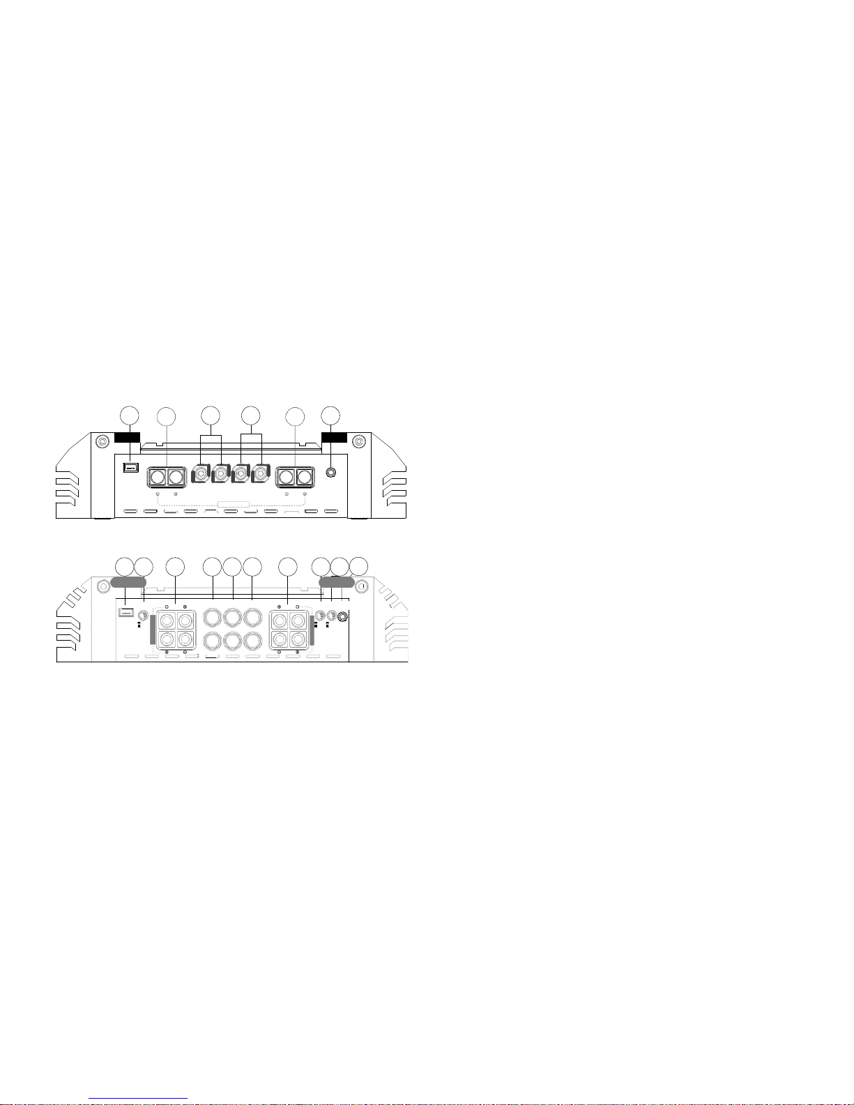
END PANEL
LAYOUTS
HCC
A10002
1
2 3 4
ESP
5 6
REMOTE
Figure 1
Figura
1
Abbil
dung
1
2.
Speakers (Left channel) -Connect the speakers to these terminals.
(HCCA10002 only, refer to the Speaker Connections section of
this guide.)
3. Input - Accepts RCA input from a head unit, preamplifier, or
equalizer (HCCA10002 only).
4. RCA Line Output - Provides easy connection to additional ampli-
fiers, the RCA inputs and RCA output are the same signal and are
not affected by any amplifier functions.
5. Speakers (right channel) - HCCA10002 only see item
2
L R L R
GAIN
I
NPUT
INPU
T OUTPUT
O
UT
PUT
HCCA
10004
L CH
R
CH
BRIDGE 4 OHM
6. Remot
e Gain Input - Connects optional RGC2 remote gain control
to control the gain level from the driver’s seat.
7. GAIN RANGE - Selects the input sensitivity range to either High
(for high power head units) or Low (for line level head units).
1
7 8
9 4
10
11
12
13 6
8. Sp
eakers (Left Front and Right Front below) -Connect the speak-
ers to these terminals. (HCCA10004 only, refer to the Speaker
Connections section of this guide.)
LF L LR
GAI
N
RANGE LF
HIGH
INPU
T OUTPUT
INPUT
CH LINE
REMOTE
LR MODE OUT
GAIN
2 CH
F/R SUM
9. Input (Le
ft Front and Right Front below) - Accepts RCA input from
a head unit, preamplifier, or equalizer (HCCA10004 only).
ESP
LOW
4 CH PASS
RF
RF
R RR
RR
10.
11.
Figure
2
12.
Figura 2
Abbildung
2
13.
I
nput (L
e
ft Rear and Right Rear below) - see item 9
Speakers (Right Rear and Left Rear below) -see item 8
2/4 Channel Switch - 2ch setting will allow 4 channel output with
a signal only present on the front inputs. 4 ch will allow a 4 channel output when signal is present on the front and rear inputs.
Front/Rear Sum Switch - Allows you to sum the front and rear
channels together before sending the signal out the RCA line out.
1. ESP - Allows connection of a MD Audio Engineering ESP
controller, like the
Bitwriter.
If the switch is not engaged, then only the front left and front
right signals are sent to the RCA line out.
Page 3
1
2 3 4
ground
terminal or any other factory ground points.
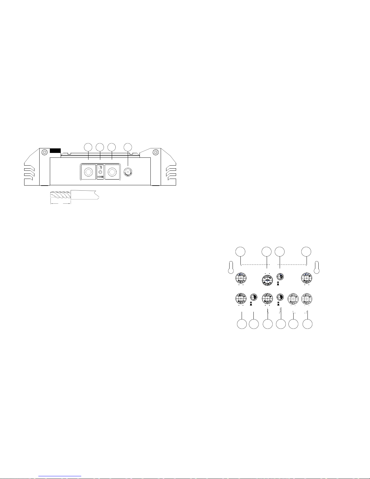
4. Top cover lock - Use the key provided or the 3mm hex key to
unlock and remove the top cover.
Figure 3
Figura
3
A
bbil
dung
3
B+
Insulated
Wire
L
REM
GND
POWER
Recommended
wire stripping lengths
(L):
L (for Power wires): 1.0” (25
mm)
L (for Speaker wires): 0.5” (13
mm)
L (for Remote wires): 0.5” (13
mm)
NOTE: M
ake all connections to power, ground, speakers, and remote
terminals before final positioning and installation of the amplifier in
the vehicle. The top cover needs to be removed to fasten some of the
connections. These connections once made are secured by tightening
the set screws with the Allen wrench provided. These fastening set
screws are labeled and located on top of the amplifier at either end,
directly above their associated connectors.
1. +BAT
- connect this terminal through a FUSE or CIRCUIT BREAKER
to the positive terminal of the vehicle battery or the positive terminal of an isolated audio system battery.
WARNING: Always protect this power wire by installing a fuse or
circuit breaker of the appropriate size within 12 inches of the battery
terminal connection.
2. REM - this terminal turns on the amplifier when (+) 12 volt is
applied. Connect it to the remote turn on lead of the head unit
or signal source. If a (+) 12 volt remote turn lead is not available,
4/0
0ANEL
,AYOUT
NO
TE: T
op
cover must be removed to access the following controls
(Refer to the Removing the Top Cover section of this manual). These
controls are duplicated for the HCCA10004 (a separate set of controls
for Front and Rear channels).
1
2 3
4
X-OVER
a Remote Po
wer Adapter (P/N ORRPA) can be used to supply a
remote turn on signal. DO NOT connect this terminal to constant
(+) 12 volt.
HIG
H
PASS
ALL
SLO
PE
LOW
HIGH
24dB
LOW
PASS
3. GND -
power return connection. Connect this terminal directly
to the sheet metal chassis of the vehicle, using the shortest wire
necessary to make this connection. Always use wire of the same
50
2K
HZ HZ
HIGH
12dB
OFF
50
2K
HZ HZ
MIN
MAX LOW
15
60
ON
0 10
20 200
gauge or
larger than the (+) 12 volt power wire. The chassis con-
HZ
HZ
GAIN GAI
N
dB dB HZ HZ
nect
ion point should be scraped free of paint and dirt. Use only
quality crimped and/or soldered connectors at both ends of this
wire. DO NOT connect this terminal directly to the vehicle battery
Figure
4
Figura 4
Abbildung 4
RANGE
10 9
Q FREQ
INFRA
SONIC INTELLI-Q
8 7 6
5
Page 4
1. HIGH PASS -
Adjusts the lower crossover frequency of the ampli-
fier.
2. CROSSOVER SELECTION - ALL is the full range setting, LOW is the
low pass setting and HIGH is the high pass setting.
3. SLOPE - Selects the crossover roll off between 12db and
24d
b
per o
ctave.
4. LOW PASS - Adjusts the upper crossover frequency of the amplifier.
5. FREQ - Adjusts the center frequency of the Intelli-Q between 20
and 200 Hz.
6. Q - Continuously adjusts the “Q” boost of the high-pass crossover
from 0 to 10dB of boost.
REMOVING THE TOP COVER
Top C
over
Figure 5
Figura
5
Abbil
dung
5
Lock
Key
7. ON/OF
F - Turns the Intelli-Q on or off.
8. Infrasonic (Subsonic) Switch - When On cuts off extremely low
bass frequencies (below the range of human hearing that speakers cannot effectively reproduce). The high pass filter is engaged
when the infrasonic switch is On. This improves efficiency of the
amplifier’s power supply, improves sound reproductive performance, and reduces chances of damaging the subwoofers.
1. Inser
t key into lock.
2. Turn the key counterclockwise.
3. Slide the top cover away from the key while the key is still turned.
The cover only needs to slide approximately 0.25” before it can
be lifted up and removed from the amplifier.
9.
10.
GAIN RANGE
- Selects the input sensitivity range to either High
(for high power head units) or Low (for line level head units).
GAIN - Continuous adjustment for full power output.
NOTE: Whe
n installing cover, line up the pins on the bottom side of
the cover with the holes in the top of the amplifier. Slide toward the
power connectors. When the top cover shuts, it automatically locks
and does not require the key to complete.
NOTE: The top cover plate is designed to be reversible however the
LED color orientation will also appear changed when the cover is
reversed (see Amplifier Visual Troubleshooting section).
Page 5
Amplif
ier Section
HCCA
10002
HCCA
10004
Power O
utput 4Ω (Watts
rms) *
250 x 2
125 x 4
P
owe
r O
utput 2Ω (Watts
rms) **
500 x 2
250 x 4
Power O
utput 4Ω (Watts
rms) Bridged
1000
x
1
500 x 2
Ampl
ifier Efficiency
> 6
0% in
to
2Ω load
at max. power
> 55% in
to
2
Ω load
at max. power
Signa
l to Noise ratio at
rated output power and
lowest impedance
>100
dB
>100
dB
Remot
e Gain Function
Yes (RGC2 opt
ional)
Yes (RGC2 opt
ional)
Distor
tion at Rated Power
0.05% T
HD+N
0.05% T
HD+N
Fre
quency Response
20Hz to 20
kHz
+/-
2.5dB
20Hz to 20
kHz
+/-
2.5dB
Linea
r Bandwidth
10Hz
to
150kHz
+/-
3dB
10Hz
to
150kHz
+/-
3dB
Dampi
ng Factor
>
200
>
200
Input Se
nsitivity Selection
Switch
Yes
Yes
Input Se
nsitivity
200mV-4V
/ 400mv-8V
200mV-4V
/ 400mv-8V
Supply V
oltage Range
9 to
16V
9 to
16V
CEA SPECIFICATIONS SPECIFICATIONS
HCC
A10002
Powe
r Output: 250 Watts RMS x 2 at 4 ohms and
< 1% THD+N
Signal to Noise Ratio: >70 dBA (reference
1
Watt
i
nto 4 ohms)
Addit
ional Power: 500 Watts RMS x 2 at 2 ohm
at 14.4 Supply
<
1% THD+N
HCCA
10004
Power
Output: 125 Watts RMS x 4 at 4 ohms and
< 1% THD+N
Signal to Noise Ratio: >70 dBA (reference
1
Watt
i
nto 4 ohms)
Addit
ional Power: 250 Watts RMS x 4 at 2 ohm
at 14.4 Supply
<
1%
THD+N
Page 6

SPECIFICATIONS (continued)
Amplif
ier Section
HCCA
10002
HCCA
10004
Prot
ection
The
rmal, DC offset, short protection, under-
voltage, over-voltage
Term
inal Wire Gauge
Power 4 AWG
Remot
e 12 - 16
AWG
Ground 4 AWG
Spe
aker 8 - 12
AWG
Power 4 AWG
Remot
e 12 - 16
AWG
Ground 4 AWG
Spe
aker 8 - 12
AWG
Input Im
pedance,
Balanced line
20 k
Ω
20 kΩ
Fuse Size
100 Amp
100 Amp
Balan
ced Line Inputs
Yes
Yes
Dimensions (L x W x H)
19.75”x 10.3”x
2.5” 19.75”x 10.3”x
2.5”
Cross
over Section
High P
ass Crossover
Continuous
ly variable
(50-2kHz)
Continuous
ly variable
(50-2kHz)
Low P
ass Crossover
Continuous
ly variable
(50-2kHz)
Continuous
ly variable
(50-2kHz)
Inte
lli-Q
0-10dB
0-10dB
* Continuous
4Ω load 20Hz to 20kHz, < 1% THD, with input voltage at 14.4 VDC.
** Continuous 2Ω load 20Hz to 20kHz, < 1% THD, with input voltage at 14.4 VDC.
AMPLIFIER SETTINGS
3IGNAL)NPUT
AND
/UT
PUT
#ONFI
GURATIONS
The
input section of the amplifier consists of gain controls, high pass
and low pass crossovers controls, Intelli-Q control and RCA inputs and
outputs. The input section makes it easy to adapt this amplifier to
most system configurations.
)NPUT'AIN
These
Orion amplifiers have level adjustments to allow for easy integration with any source unit. The input sensitivity is a push button
adjustment, with the depressed (in) position giving you a range from
400
mV
to 8V while in
the out position this range is 200mV to 4V. Refer
to Testing the System and Adjusting the Sound of the System sections
of this guide for detailed instructions on setting the gain.
!DJUST
ING
)NT
ELLI-1
Incor
porated in the high-pass crossover, Intelli-Q maximizes the
performance of a subwoofer. The high-pass subsonic filter removes
unwanted bass output from the woofer, increasing the output of a
subwoofer by as much as 3 dB due to the increased mechanical power
handling. Depending on the enclosure, using Intelli-Q can increase the
low frequency response by an additional 10dB! The type of enclosure
used and the woofer’s excursion capability determine acceptable
boost levels. Listed next are recommended boost levels for different
enclosure designs.
Page 7

Enclosure
Type
Boost Levels
0dB +3dB +6dB
+10dB
Infinite
Baffle
Tune above Fs
of woofer
High X-Max
Drivers - Tune
above Fs of
woofer
Not
Recommended
Not
Recommended
Sealed Tune above Fs
of woofer
Tune above Fs
of woofer
High X-Max
Drivers - Tune
above Fs of
woofer
Not
Recommended
Vented Tune to port
frequency
Tune to port
frequency
Tune to port fre-
quency
High X-Max
Drivers -Tune to
port frequency
Sealed
Band-pass
Tune above Fs
of woofer
Tune above Fs
of woofer
High X-Max
Drivers - Tune
above Fs of
woofer
Not
Recommended
Vented
Band-pass
Tune to port
frequency
Tune to port
frequency
Tune to port fre-
quency
High X-Max
Drivers -Tune to
port frequency
Aperiodic Set crossover to
Fs of woofer
Set crossover to
Fs of woofer
Set crossover to
Fs of woofer
Not
Recommended
pass
, and band-pass operation. This circuit is designed to optimize the
performance of subwoofers in all types of enclosures.
When using Orion loudspeakers, minor deviations from the recom-
mended frequency ranges can provide superior results depending on
your speaker locations and your vehicle acoustics. Setting crossover
frequencies higher than recommended will not cause damage and
may provide superior sonic results depending on your system’s performance goals. Refer to your loudspeaker owner’s manual for assistance
in choosing the proper crossover frequencies for your system.
WARNING! DO NOT set crossover frequencies lower than the speakers recommended operating range. This can cause driver failure that
is not covered by the manufacturer’s warranty.
#ROS
SOVER3WITCH
Con
trols the type of filter for the onboard active crossover. The
HCCA10004 has two switches, the upper switch is for channels 1/2, the
lower switch is for channels
3/4.
,INE/UT
PUT
#ONFI
GURATIONS
The line o
utputs on Orion amplifiers offer easy system expansion and
can be used to route signal from the RCA line outputs to the next
Orion amplifier’s RCA line inputs in the signal chain.
)NTE
RNAL
#ROS
SOVER
#ONFI
GURATIONS
The
crossover section of the Orion HCCA10002 and HCCA10004 amplifiers are continuously variable and extremely flexible. There are eight
different crossover configurations possible allowing high-pass, low-
All position does not attenuate any frequencies and is for full
range speaker systems.
High attenuates low frequencies and is used for mid-range speakers and tweeters.
Low attenuates high frequencies and is used for subwoofer
speakers.
,OW-0ASS
#ROS
SOVER
When
the switch is in the middle (ALL position), the low-pass crossover
is bypassed. When the switch is to the left (LOW position), the lowpass crossover is active. The low-pass crossover is continuously variable
from 50Hz to
2kHz.
Page 8

(IGH-0ASS#ROS
SOVER
When t
he switch is in the middle (ALL position), the high-pass crossover is bypassed. When the switch is to the right (HIGH position), the
high-pass crossover is active. The high-pass crossover is continuously
variable from 50Hz to
2kHz.
2EMOT
E'AIN/PERATION(OPTIONAL)
The rem
ote gain port provides easy remote access to the internal gain
structure of the HCCA power amplifier. The optional RGC2 plugs into
the amplifier via the 1/8” mini jack plug. The RGC2 can be installed
in the front of the vehicle near the driver’s position to control the
amplifier gain level. On HCCA10004, it only affects the rear channels
by default.
)NFI
NITE
"AF
FLE
%XAMPLE(IGH-0ASS
SETAT20(Z
By re
moving low frequency signal that the woofer cannot produce,
the woofer can play its capable range louder. The first example is
an infinite baffle situation. The left graph displays the frequency
response of a 12-inch woofer in an infinite baffle application without
the high-pass filter. As you can see, with +3dB of boost and the high
pass filter set to 30Hz, the woofer has more output down to 25Hz and
less overall excursion when compared to the non-high-pass response.
Maximum physical excursion capability of the woofer is
15mm.
Figure
6
Figura 6
Abbildung 6
Figure 7
Figura
7
Abbil
dung
7
NOTE: The fi
rst graph is the response; the second graph is the driver
excursion. These designations apply to the following graphs as well.
Page 9

3EA
LED
%XAMPLE(IGH-0ASS3ETAT20(Z
This
sealed example is the same 12-inch woofer in the recommended
sealed enclosure. Up to 6 dB of boost is capable if 20 Hz was used.
With +6dB of boost, the woofer has more output down to 15 Hz.
Figure
8
Figura 8
Abbildung 8
Figure
9
Figura 9
Abbildung 9
3EA
LED
%XAMPLE(IGH-0ASS3ETAT30(Z
In this
example, the frequency has been increased to 30 Hz. Up to
6 dB of boost is capable at this frequency. With +6dB of boost, the
woofer has more output down to 23 Hz. The overall usable output is
increased.
Figure 10
Figura
10
Abbil
dung 10
Figure 11
Figura
11
Abbil
dung
11
Page 10

6EN
TED
%XAMPLE(IGH-0ASS3ETAT30(Z
Vent
ed enclosures benefit most from the Intelli-Q. Up to 10 dB of
boost is capable at the box tuning frequency of 30 Hz. With
+10d
B
of boost
, the woofer has more output down to 22 Hz. The excursion
below the tuning frequency has been greatly reduced.
Figure 12
Figura
12
Abbil
dung
12
Figure 13
Figura
13
Abbil
dung
13
AMPLIFIER WIRING
0OWER
#ONNE
CTIONS
s Ori
on HCCA10002 Fuse Size: 100 Amp.
s Orion HCCA10004 Fuse Size: 100 Amp.
s Power connections accept up to 4 AWG wire.
s 4 AWG power and ground wire must be used for optimal per-
formance.
s Connect 12V+ to the battery through a fuse holder. This connec-
tion provides +12V main power to the amplifier.
s Power wire must be fused no more than 12” from battery.
s Ground amplifier to a good chassis ground as close as possible to
the amplifier.
s Recommended fuse is 100A for both amplifiers.
s Connect REM terminal to remote turn-on lead from source unit.
This connection provides +12V power to turn-on the amplifier.
s Add extra ground wire between the negative terminal of the
battery and the chassis.
NOTE: Th
e addition of a ground wire from the battery to the chassis
of the vehicle improves the ability of the battery to supply power to
the amplifier. This is recommended because the current delivery of the
factory electrical system was designed only to accommodate electronics supplied by the auto manufacturer.
Page 11

3PEAKER
#ONNECTIONS(##!10002
The Or
ion HCCA10002 amplifier offer one positive and one negative
output terminal for ease of connecting channel 1(L CH) and/or 2(R CH)
outputs to the speakers. The amplifier is stable to 2Ω per channel. See
diagrams below.
One Channe
l/Two Channel Configuration
s Lowe
st recommended impedance is 2Ω stereo.
s Outputs can be configured for high-pass, low-pass, or full range
operation.
Three Channe
l (L Channel, R Channel, Bridged)
s Left
and Right are configured for two-channel stereo operation.
s Lowest recommended impedance is 2Ω stereo.
s The third output is configured for a single channel bridged out-
put.
s The bridged outputs lowest recommended impedance is
4Ω.
s Outp
uts are configured for high-pass, low-pass, or full range
operation.
Figure 14
Figura
14
Abbil
dung
14
L CH R CH
L CH R CH
Bridge
Configuration
Bridgi
ng allows one speaker to be driven at a higher power level from
the amplifier.
s The bridged outputs lowest recommended impedance is
4Ω.
Figure 16
Figura
16
A
bbi
l
dung
16
Figure 15
Figura
15
Abbil
dung
15
L CH R CH
NO
TE:
To ge
t full output in this configuration, band limiting filters as
shown in this diagram may need to be used to prevent the impedance
from dropping too low and engaging protection circuits.
Page 12

3PEAKER
#ONNECTIONS(##!10004
The Or
ion HCCA10004 amplifier offers four positive and four negative
output terminals for ease of connecting channel 1(LF), 2(RF),
3(RR),
and 4
(LR) outputs to the speakers. The amplifier is stable to 2Ω per
channel. See diagrams below for possible configurations.
Four Ch
annel Stereo Configuration
s Chan
nel 1/2 and channel 3/4 lowest recommended impedance is
2Ω stereo.
s Crossover mode, output, and gain configurations are indepen-
dently adjustable between the front and rear channels.
s Two-channel or four-channel input can be used for this configu-
ration. For source unit fading, use the four-channel input mode.
s Channels 1/2 and channels 3/4 outputs can be individually config-
ured for high-pass, low-pass, or full range operation.
Three
Channel Configuration
s Channe
ls 1/2 are configured for 2-channel stereo operation.
s Channel 1/2 lowest recommended impedance is 2Ω stereo.
s Channels 3/4 are configured for a single channel bridged out-
put.
s Channel 3/4 lowest recommended bridged impedance is
4Ω.
s Cross
over mode, output, and gain configurations are indepen-
dently adjustable between channels 1/2 and
3/4.
s Two-c
hannel or four-channel input can be used for this configu-
ration. For source unit fading, use the four-channel input mode.
s Channel 1/2 and 3/4 outputs can be configured for high-pass, low-
pass, or full range operation.
s Channel 3/4 outputs are configured for summed bridged opera-
tion for subwoofer.
LF LR
LF LR
RF
Figure 17
Figura
17
Abbil
dung
17
RR
RF RR
Figure 18
Figura
18
Abbil
dung
18
Page 13

Five Ch
annel Configuration
s Channe
ls 1/2 are configured for 2-channel stereo operation.
s Channel 1/2 lowest recommended impedance is 2Ω stereo. Lowest
recommended impedance is 2Ω stereo and 4Ω bridged mono.
s Rear outputs must be set for full range operation.
s Passive crossovers must be used on all components and frequen-
cies must not overlap.
Tri-
Mode Six Channel Configuration
s Lowe
st recommended impedance is 2Ω stereo and 4Ω bridged
mono.
s Front and rear outputs must be set for full range operation.
s Passive crossovers must be used on all components and frequen-
cies must not overlap.
WARNING! Failure to observe these requirements may result in damage to the amplifier.
LF
LR
RF
RR
LF LR
RF
RR
Figure 19
Figura
19
Abbil
dung
19
NOTE: To g
et full output in this configuration, band limiting filters as
shown in this diagram may need to be used to prevent the impedance
from dropping too low and engaging protection circuits.
Figure
20
Figura 20
Abbildung 20
NOTE: To ge
t full output in this configuration, band limiting filters as
shown in this diagram may need to be used to prevent the impedance
from dropping too low and engaging protection circuits.
Page 14

AMPLIFIER INSTALLATION
#HOO
SING
-OUNT
ING
,OCAT
IONS
The lo
cation of your amplifier will depend on several important issues.
Due to the low profile size of the Orion amplifiers, there are many
possible installation locations that will yield satisfactory amplifier
performance. Always mount the amplifier in a place that protects the
amplifier from the elements. In addition, mount the amplifier on a
stable, flat surface.
NOTE: Mounting amplifiers upside down is not recommended and
may cause premature thermal shutdown.
WARNI
NG! Do not mount any amplifier in the engine compartment.
Amplifiers are not designed to endure the harsh environment of the
exterior elements.
0ASS
ENGER
#OMP
ARTMENT
If y
ou are going to mount the amplifier in the passenger compartment, make sure you have adequate room for ventilation. The amplifiers have been designed to make under-seat mounting possible. When
mounting your amplifier under a seat or similar area, keep a minimum
of 1” of clearance around the amplifier for adequate cooling.
4RUNK
#OMP
ARTMENT
Mounti
ng your amplifier in the trunk provides excellent performance
as long as you do not restrict the airflow around the heatsink of the
amplifier. For optimal results, mount the amplifier with as much clear-
ance as possible. This type of mounting will yield the best cooling due
to the convection effect of the amplifier chassis.
'ENE
RAL
0RE
CAUTIONS
AND
)NS
TALLATION
4IPS
WARNI
NG! Be careful not to cut or drill into gas tanks, fuel lines,
brake lines, hydraulic lines, vacuum lines, or electrical wiring when
working on your vehicle.
Disconnect the vehicle’s ground wire at the battery before making or
breaking connections to the audio system’s power supply terminals.
Do not
use this amplifier unmounted. Failing to securely mount the
amplifier can result in damage or injury, particularly in the event of
an accident. An unmounted amplifier becomes a dangerous projectile
in the event of a crash. Never mount the amplifier where it might get
wet. Mount the amplifier so the wire connections will not be pulled.
Route the wires where they will not be scraped, pinched or damaged
in any fashion.
The +
12V power supply wire must be fused as close as possible to
the battery terminal, ideally within 12”. Use the recommended fuse
size or circuit breaker listed in the Power Connections section of this
manual.
If you need to r
eplace the fuse plugged into the side of the amplifier,
replace the fuse with the same size and type fuse that came with the
amplifier. If you are not sure as to the correct value, refer to the Power
Connections section of this manual for details. Using a higher current
fuse may result in damage to the amplifier that is not covered under
warranty.
Page 15

NOTE: Make s
ure all the equipment in the system is turned off when
making or breaking connections to the input RCA’s or speaker terminals. Turn on the system and slowly turn up the volume control only
after double checking all wire connections.
Powe
r for systems with a single amplifier can be supplied by most
automotive electrical systems. Systems with multiple amplifiers may
require a higher capacity battery, alternator or the use of a storage
capacitor. We strongly recommend the use of an Orion Wired power
capacitor with an extra battery in larger stereo systems.
Orio
n amplifiers generate a certain amount of heat as part of normal
operation. Be sure the area around the amplifier is unobstructed to
allow adequate air circulation. Remember, beach blankets, last week’s
laundry, school books and homework papers located on top of the
amplifier do not improve air flow and may become damaged.
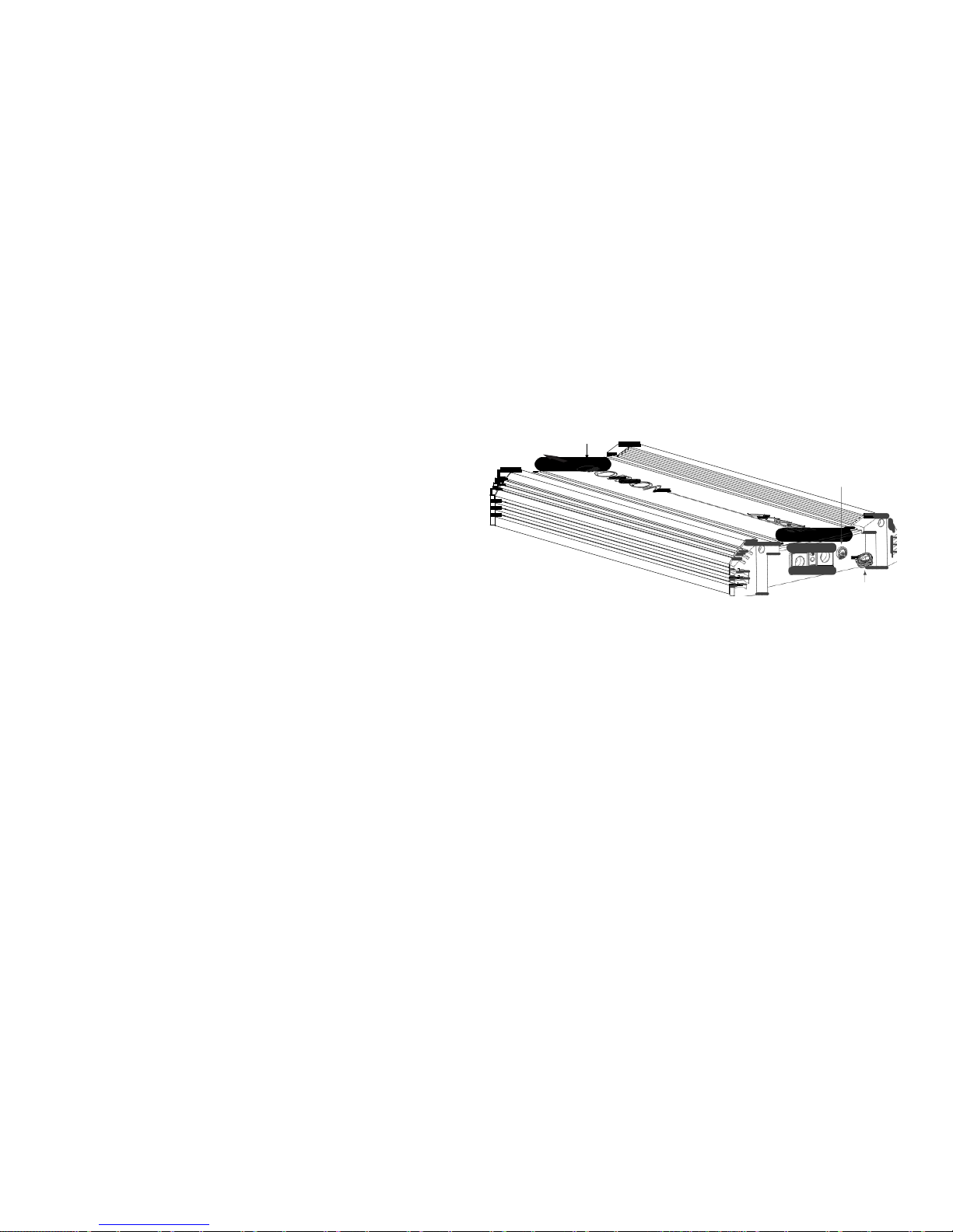
You mus
t first remove the top cover (see Removing the Top Cover
section) then end caps to mount the amplifier (mounting holes are
within). (1) Remove the screws first, (2) lift the end cap straight up
to detach from unit and then (3) pull away from the amplifier. Once
mounted replace end caps by following this process in reverse.
3
4OOLSOFTHE
4RADE
List
ed below are the majority of the tools required to perform an
installation. Having the proper tools will make the installation that
much easier. Some of these tools are necessities; some will just make
the job easier.
s Allen Wr
enches (3mm and 4mm)
s DMM or VOM
s Electric drill with assorted drill bits
s Grommets
s Heat shrink tubing
s Marking pen
s Nylon tie straps
s Phillips and flat blade screw drivers
s Pliers (standard and needle nose)
s Reference CD with
1
kHz Sine
Wave at 0dB level (all bits high)
s RTA (real time analyzer)
s
Sold
ering iron and solder
s Utility knife
s Wire brush or sandpaper for chassis grounding
s Wire crimper
Figure 21
Figura
21
Abbil
dung
21
2
1
s
s
Wire cu
tters
Wire strippers
Page 16

3TEP"
Y3TEP)NSTALLATION
NOTE: Conne
ct all input, power and speaker connections to amplifier
before mounting the amplifier in its final location.
1. Determine the location for the amplifier. Refer to the Choosing
Mounting Locations section of this guide for detailed information.
2. Decide on the system configuration for your amplifier. For system
suggestions, refer to the Speaker Connections section of this
guide.
3. Run all the wires from the amplifier location to the speakers,
source unit, and battery. Do not connect the battery at this time.
Be sure to run RCA’s and power and speaker wires away from
factory electrical wires and system as they pose a great potential
for induced system noise.
4. Remove end caps before mounting the amplifier.
5. Pre-drill amplifier mounting holes. Be sure to “think before you
drill”. Gas tanks, fuel lines, mechanical/electrical systems and/or
other obstructions may be hidden beneath mounting location.
For best results use a marking pen to mark the mounting holes
10.
11.
12.
13.
14.
15.
Connec
t the RCA and speaker wires to the amplifier. Check the
quality of your speakers and signal connections. This will determine the ultimate performance of your Orion amplifier. Refer
to the Signal Input and Output Configurations and Speaker
Connections sections of this guide for correct wiring instructions.
Reconnect the ground terminal to the battery after power,
speaker, and RCA connections are completed.
Set crossovers. Refer to the Internal Crossover Configuration section of this manual for detailed instructions.
Set gain control to a low level before turning on the amplifier.
Adjust gain control as needed after the system is playing. (see
adjusting the sound of the system)
Once satisfied that all connections and settings are correct, install
the fuse located near the vehicle’s battery and proceed to the
Testing the System section of this manual.
After all connections and adjustments are made, install end caps
if they are to be used.
and pre-drill these holes with a standard 1/8” drill bit.
6. Mount the amplifier. Make sure the amplifier is mounted on a
flat surface. If this is not possible, do not over tighten the screws
so that the chassis of the amplifier is twisted or bent.
7. Turn the vehicle’s key switch to the off position.
8. Disconnect the vehicle’s battery ground terminal.
9. Connect power wires to the amplifier (ground first, then 12 V(+)
and REM). Power wire must be fused near the battery. Be sure to
remove the fuse from the fuse holder at this time.
WARNING! Never exceed the recommended fuse size of this amplifier.
Failure to do so will result in the voiding of your warranty and possible
damage to the amplifier.
Page 17

SETUP AND TROUBLESHOOTING
4ESTING
THE
3YSTEM
After y
ou have completed the installation, you need to test the
system. This will help ensure years of trouble-free operation. Please
refer to the listed steps below when testing the sound of your Orion
system.
1. Check
all the wiring connections to be sure they are correct and
secure.
2. Turn the signal source volume control all the way down. Set any
tone controls to their flat or defeated positions. This includes the
loudness control.
3. Turn the level controls of the amplifier to their minimum posi-
tions.
4. Turn the source unit on. Check to see if the power LED located
on the top of the amplifier is on. If not, please refer to the Power
Connections and the Troubleshooting Tips sections of this manual
for instructions.
5. If using an aftermarket source unit, turn the level controls of
the amplifier about one quarter of a turn. Slowly increase the
volume level of the source unit until you can hear the output of
the system. If no sound is heard or if the output is distorted, turn
the system off immediately. Refer to the Power Connections and
the Troubleshooting Tips sections of this manual to solve your
installation problems.
6. Check to make sure the output for each channel is correct. If the
active crossovers are used, check to make sure that each output is
correct from the amplifier. When using active crossovers on midrange and tweeters, do not use crossover frequencies lower than
recommended. If the system is not configured properly, refer to
the Internal Crossover Configuration section of this manual and
take corrective action.
7. If the output is clear and undistorted, continue to the Adjusting
the Sound of the System section of this manual.
!DJUST
ING
THE
3OUNDOFTHE
3YS
TEM
Once
you have checked the system’s operation, adjust the sound of
the system. Adjusting the sound of the system is accomplished by setting the level controls and adjusting the internal crossovers.
1. Turn
the signal source volume control all the way down. Set any
tone controls to their flat or defeated positions. This includes the
loudness control.
2. Turn the level controls of the amplifier to their minimum positions.
3. Choose music with high dynamic content that you like, with which
you are familiar, and will be used most often in the system.
4. Turn the source unit’s volume control up to its highest undistorted output level. If you lack test equipment, this point occurs
between 3/4 to full volume depending on the quality of your
source unit. Listen for any audible distortion. If any distortion
is audible, reduce the volume of the source unit until you have
an undistorted output. Leave the volume control at this position
during your system tuning.
5. While listening to your chosen dynamic music, turn up the level
control corresponding to the midrange output until you hear
Page 18

6.
7.
8.
9.
10.
11.
12.
slig
ht distortion and turn the level control back slightly for an
undistorted output. Depending on your system, the midrange and
tweeter output may be on the same output channels.
Turn up the level control corresponding to the tweeter output
until you hear slight distortion and turn back the level control
slightly for an undistorted output. Depending on your system
the midrange and tweeter output may be on the same output
channels.
Fine-tune the output level between midrange and tweeters.
Refer to the Internal Crossover Configuration section of this
manual for detailed instructions.
Repeat Steps 5-7 for the rear speakers. If you do not have rear
speakers continue to Step
10.
Set
levels between the front and rear midrange and tweeters for
optimum front/rear balance.
Turn up the level control corresponding to the woofer output
until you hear slight distortion and turn back the level control
slightly for an undistorted output.
Fine-tune the output level between satellite speakers and the
woofers. Refer to the Internal Crossover Configuration section of
this manual for detailed instructions.
Enjoy your awesome Orion sound system.
Power LED: This LED lights up green when the amplifier is turned on.
This represents normal operation if the Protection/ESP Status LED is on
solid, and the Thermal LED is off.
ESP/Pro
tection Status Indicator LED: This LED lights up blue when
the amplifier is turned on and periodically blinks as a normal default
state. When the amplifier goes into protection it will flash a specific
number of times (described below) indicating the source of the event.
It will also flash when the amplifier is powering up, approximately 4-5
flashes until the turn-on delay has expired (actual number of flashes
depends on the length of time selected via the bitwriter). Below is
a description of reasons the amplifier could engage the protection
circuit. While most protection modes are self-resetting when the
problem is resolved, short or overcurrent latches and power must be
cycled off/on to restore operation. The protection indications will selfreset once the condition has been fixed. Advanced troubleshooting
can be performed using the ESP/Protection Status indicator LED.
s Short
: Speaker wires pinched or shorted together or to ground
(frame of vehicle). ESP/Protection Status LED will also flash 2 short
flashes, followed by a long pause (approximately 8-10 seconds).
s Overcurrent: Check for possible speaker issue(s) or speaker wiring
pinched in a door or other metal. Make sure speaker(s) load is
not below minimum 2Ω load. The ESP/Protection Status LED will
also flash 2 short pulses, followed by a long pause.
s
DC
Offset:
This can happen if the installation inadvertently
!MPLIFIER6ISUAL
4ROU
BLESHOOTING
Your new Or
ion HCCA amplifier has three indicator lights (LED’s) on
the top cover of the amplifier as seen in the next figure. These lights
are very useful in trouble shooting possible amplifier problems and
issues.
connects the power wire to the speaker input(s). This can also
happen if the amplifier has an internal problem. The amplifier
will flash 4 short pulses, followed by a long pause, then repeat.
s Undervoltage: Vehicle charging system is not supplying enough
voltage to the amplifier. This can also occur if you use too small
a gauge wire or the terminals connecting the amplifier power
Page 19

to t
he electrical system are dirty or corroded. The ESP/Protection
status LED also will give
1
short
flash followed by a long pause for
undervoltage. This cycle will repeat.
s Overvoltage: Vehicle charging system is supplying too much
voltage or over the amplifiers rated DC input. Usually this occurs
when there is a problem with the electrical system. Turn off the
headunit when jump-starting the car. The ESP/Protection Status
LED will also flash with
1
long
flash followed by a long pause
(approximately 8-10 seconds).
s Thermal: If the amplifier heat sink temperature is too high to
into account when installing any amplifier.
s The temperature inside the car where the amplifier is mounted is
extremely hot. This can occur in extreme climatic conditions. It
is not uncommon for temperatures inside a parked car to reach
in excess of 140°F (60°C). If airflow is restricted to the mounting
area, the main car cabin may cool down before the rest of the
car has dropped appreciably. Also, if the amplifier is near the
thermal protection temperature point, turning it on and off via
the remote line can result in it entering thermal protection.
continue safe operation, it will also enter protection mode. The
ESP/Protection status LED will give 3 short flashes followed by a
long pause. This cycle will then repeat.
Therm
al LED: This LED lights up red if the amplifier overheats. An
amplifier enters thermal protection due to conditions that might
otherwise result in damage to the amplifier. The thermal protection
mode is also indicated on the ESP/Protection Status indicator LED
Amplifier Top Cover (with LED locations)
Power
(gre
en)
Thermal
(red)
by a 3 s
hor
t fl
ash sequence that repeats every 8-10 seconds. Below
is a description of reasons the amplifier could engage the Thermal
Circuit.
s Speaker
loads lower than the amplifiers minimum 2Ω load will
cause the amplifier to draw more current and may result in
overheating. This can be avoided by using speakers or wiring
methods that result in a load greater than the amplifiers
minimum 2Ω load input. This may also result in the overcurrent
protection mode being engaged.
s The amplifier can also overheat if it is not receiving proper
ventilation, when mounting a amplifier make sure it has room for
air to circulate and keep it cool. Amplifiers will get hot because
they produce energy and care and consideration should be taken
ESP/Pr
otection Status
ind
icator
(bl
ue)
Figure 22
Figura
22
Abbil
dung
22
NOTE
: Please note that the top cover plate is designed to be reversible.
The LED colors will therefore appear to reverse their order relative to
the diagram labeling if the cover is reversed when reattached, for
example; the green LED (power) closest to the Orion logo in the
diagram will be the furthest from the logo with the cover reversed.
Page 20

4ROU
BLESHOOTING4IPS
Sympt
om Probable Cause Action To Take
No output
Low or no remote turn-on Check remote turn-on voltage at voltage amplifier and repair as needed.
Fuse blown Check power wire's integrity and check for speaker shorts. Fix as needed
and replace fuse.
Power wires not connected Check power wire and ground connections and repair or replace as needed.
Audio input not connected. Check RCA connections and repair or replace as needed.
Speaker wires not connected Check speaker wires and repair or replace as needed.
Speaker are blown Check that ESP status indicator is not indicating an active event. Check sys-
tem with known working speaker and repair or replace speakers as needed.
Audio cycles on and off
Thermal protection engages when amplifier heat
sink temperature exceeds 75º C (167º F)
Make sure there is proper ventilation for amplifier and improve ventilation
as needed.
Loose or poor audio input Check RCA connections and repair or replace as needed.
Loose power connections Check power wires and ground connections and repair or replace as needed.
Distorted output
Amplifier level sensitivity set too high exceeding
maximum capability of amplifier , resulting in
distorted sound
Readjust gain. Refer to the Adjusting the Sound of the System section of this
manual for detailed instructions.
Impedance load to amplifier too low Check speaker impedance load, if below 2Ω, rewire the speakers to achieve
higher impedance.
Shorted speaker wires Check speaker wires and repair or replace as needed.
Page 21

Sympt
om Probable Cause Action To Take
Speaker not connected to amplifier properly. Check speaker wires and repair or replace as needed. Refer to the Speaker
Connections section of this manual for detailed instructions
Internal crossover not set properly for speakers Readjust crossovers. Refer to the Internal Crossover Configuration section of
this manual for detailed instructions.
Speakers are blown Check system with known working speakers and fix or replace as needed.
RCA shield connection is intermittent or faulty Replace/Repair RCA cable.
Poor bass response
Speakers wired with wrong polarity causing cancellation at low frequencies.
Check speaker polarity and fix as needed.
Crossover set incorrectly Reset crossovers. Refer to the Internal Crossover Configuration section of
this manual for detailed instructions.
Impedance load at amplifier is too low. Check speaker impedance load if below 2Ω, rewire speakers to achieve
higher impedance .
Battery fuse blowing
Short in power wire or incorrect wiring. Check power wires and ground connections and repair or replace as needed.
Fuse used is smaller than recommended. Replace with proper fuse size.
Actual current exceeds fuse rating. Check speaker impedance load if below 2Ω, rewire speakers to achieve
higher impedance .
Speaker is blown with shorted outputs Check system with known working speakers and fix or replace as needed.
Page 22

ESP®-2
Status Indicator LED
Mode
Off
Amp
lifier Off
5 short f
lashes, pause, then repeats
Unit poweri
ng up
Soli
d Illumination
Norma
l Operation
1
long f
lash, pause, then repeats
Overvo
ltage
1
short
flash, pause, then repeats
Underv
oltage
2 short flash
es, pause, then repeats
Ove
rcurrent
3 short
flashes, pause, then repeats
The
rmal protection
4 short fla
shes, pause, then repeats
DC offset
APPENDIX—PROGRAMMABLE FEATURES
The f
ollowing listing are ESP
®
-2 featu
res that can be programmed or
accessed by your installer to customize or troubleshoot your system.
Factory default settings are shown in bold.
NOTE: The Bitwriter® must have software version 2.7 or above to
access the amplifier features menu.
NOTE: A setting marked “Reserved” is for future development. Some
settings are read-only, i.e. they cannot be changed, only viewed. If
changed, the bitwriter will fail verification of the parameters upon
write and indicate an error.
Turn
On Delay - 1.5, 2.0, 2.5, 3.0, 3.5, 4.0 seconds. Delays the amplifier
turn-on when the head or source unit is turned on. This eliminates any
annoying pops or noise during power up from the head or source unit
from feeding through to the amplifier.
Input Gain Range (Volts) - The position of the gain switch determines
the gain range available. If the gain switch is in the high mode, the
ranges are Default (0.2 - 4V), 0.2-1V,
1-1.5V
,1.5
- 3.5V
, 3.5-4V. If the
gain switch is in the low mode, the ranges are Default (0.4 - 8V), 0.4 2V, 2 -3V, 3V - 7V, 7-8V.
NOTE: If t
he Input Gain Adjustment is set to Lock (see below), the
Input Gain Range adjustment will not be altered until the Input Gain
Adjustment is set to Unlock.
Input
Gain Adjustment - Unlock, Lock. When set to “Lock”, the input
gain adjustment is disabled. This can be set to lock after the amplifier
has been installed and set up to prevent accidental or unwarranted
adjustment.
NOTE:
Use caution when adjusting or unlocking gain as restricting
the range or unlocking the range can result in sudden increases in
gain. We recommend turning down the source to avoid damage to
speakers and/or your hearing prior to exiting this mode.
Eve
nt 1 through 7 - Stores up to seven recent events that have
occurred to aid in diagnostic troubleshooting. The events that are
retained are: Undervoltage, Overvoltage, Reserved, No Fault, Thermal,
Overcurrent. These events are read-only, the amplifier will not allow
them to change, even if they are changed on the bitwriter, they cannot be written to the amplifier by the installer. Event
1
is the most
recent event, then Event 2, and so on. If event memory is full (Event
7
has a
stored diagnostic message), then if another event occurs the
7th
event
will be pushed out of memory.
NOTE: Wh
ile the Bitwriter
®
can be used
to read the amplifier during
Page 23

an even
t, the priority of the amplifier is given to continually checking
its health. Attempts to Write to the amplifier during and immediately
following an event may result in communication errors.
Ex
cep
for overcurrent/short, the amplifier should clear any faults
t
when the condition that causes them clears. Substantial changes to
the amplifier parameters via the bitwriter may result in the audio
being interrupted momentarily. Also, the amplifier is designed to
fade up from protection events and when turned on.
NOTE: Th
battery terminals and keeping the remote line off for at least
onds.
sec
e amplifier can be reset by removing power to the main
30
The maj
referenced should it be necessary to contact MD Audio Engineering or
Orion.
or and minor revision levels of the ESP2 software should be
Orion Car Audio
Car Amplifiers
 Loading...