

Page 1
FACTORY CONTROLS SYSTEM
HB Mini - Controller
Technical Guide
Page 2

Table Of Contents
Controller Overview ........................................................................................................................ 3
General ...................................................................................................................................................................................... 3
Inputs ......................................................................................................................................................................................... 3
Outputs ...................................................................................................................................................................................... 3
Controller Sequence Of Operation ................................................................................................. 4
Fan Mode ................................................................................................................................................................................... 4
Heating Mode ............................................................................................................................................................................ 4
Cooling Mode ............................................................................................................................................................................ 4
Lockout Modes ......................................................................................................................................................................... 4
Controller Installation & Wiring ...................................................................................................... 5
Controller Mounting ................................................................................................................................................................. 5
Important Wiring Considerations............................................................................................................................................ 5
Programming With The HB Service Tool...................................................................................... 11
Entering Passcodes ................................................................................................................................................................ 11
General Procedures ................................................................................................................................................................11
Module Selection Screens..................................................................................................................................................11
HB Mini Controller Status & Setpoints ................................................................................................................................. 12
Main Status Screens.......................................................................................................................................................... 12
Fan Module Status Screens .............................................................................................................................................. 13
Cooling Module Status Screens ........................................................................................................................................ 13
Cooling Module Setpoint Screens ..................................................................................................................................... 14
Heating Module Status Screens........................................................................................................................................ 15
Heating Module Setpoint Screens..................................................................................................................................... 16
Alarm Module Status Screens........................................................................................................................................... 16
HVAC Test Module Screens .............................................................................................................................................. 17
Troubleshooting ............................................................................................................................ 19
Using LEDs To Verify Operation ............................................................................................................................................ 19
HB Mini Controller Fault Condition Operation ................................................................................................................... 19
Appendix ........................................................................................................................................ 20
Notes: ............................................................................................................................................ 22
WattMaster Controls Inc.
8500 NW River Park Drive · Parkville , MO 64152
Toll Free Phone: 866-918-1100
PH: (816) 505-1100 · FAX: (816) 505-1101 · E-mail: mail@wattmaster.com
Visit our web site at www.wattmaster.com
Form: AA-HBM-TGD-01A Copyright 2005 WattMaster Controls, Inc.
AAON® is a registered trademark of AAON, Inc., Tulsa, OK.
WattMaster Controls, Inc. assumes no responsibility for errors, or omissions.
This document is subject to change without notice.
Page 3
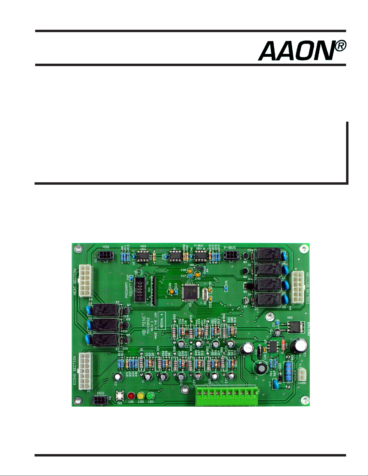
Controller Overview
Technical Guide
General
The HB Mini Controller is designed to work with a normal 24 VAC
Thermostat. Single or Multi-stage Thermostats can be used. When a
Single Stage Thermostat is used, an auto-staging feature is built-in for
Multi-stage HB units.
The HB Mini Controller also monitors equipment safeties, logs information and locks out the equipment in the event of multiple failures.
Terminal block style connections are provided for field wiring of the
Thermostat. All other inputs and outputs are connected via a wiring
harness on the HB unit. A list of all available inputs and outputs follows.
Inputs
G, Y1, Y2, W1, W2, W3
Outdoor Air Temperature Sensor
Heat Safety Monitor (monitors main and auxiliary limit thermostats)
High Pressure Switch
Low Pressure Switch
Clogged Filter Switch
Outputs
Supply Fan High Speed Relay
Supply Fan Low Speed Relay
Cool-1 Relay
Cool-2 Relay
Heat-1 Relay
Heat-2 Relay
Heat-3 Relay
C1, C2: Clogged Filter Switch 24 VAC Output Terminals
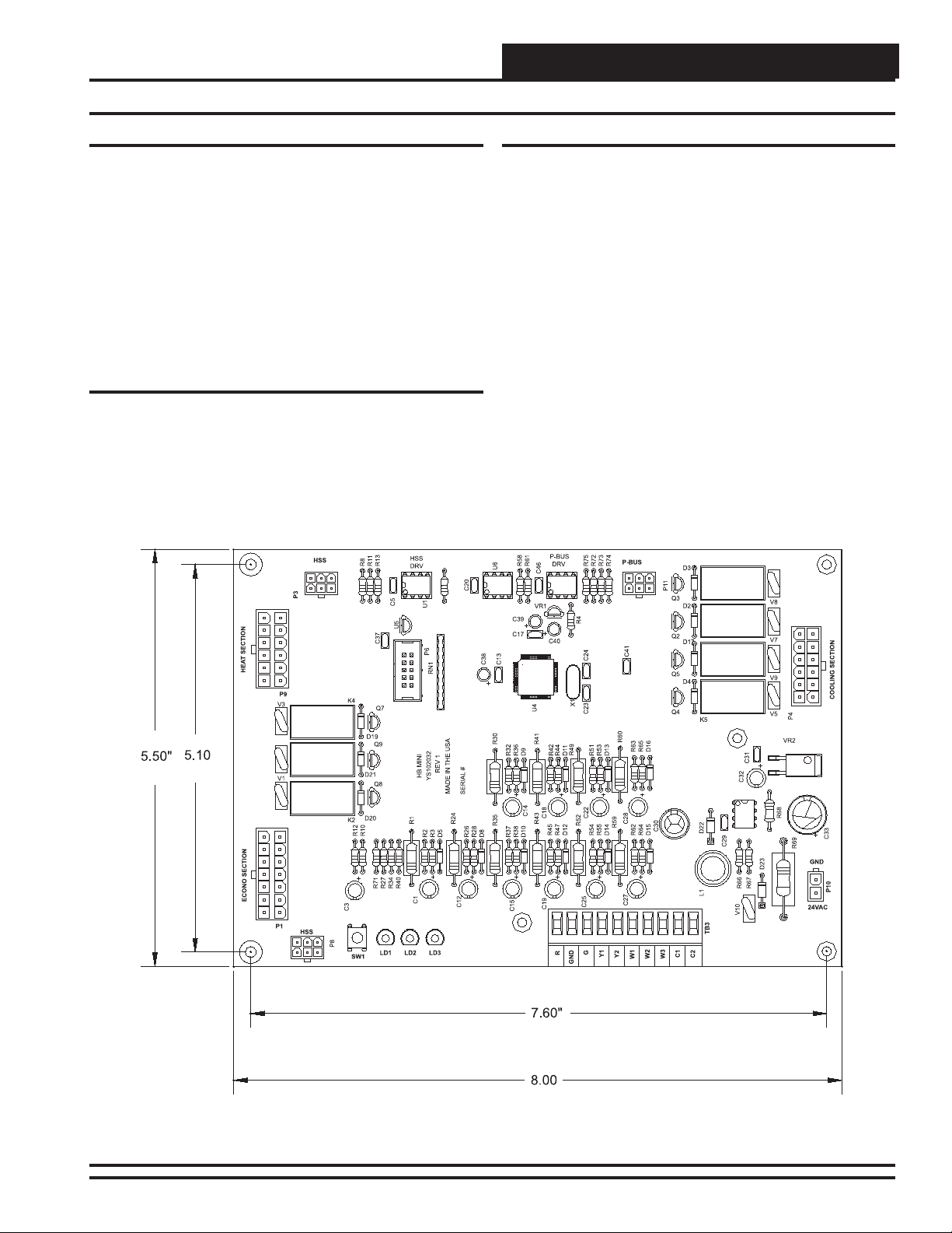
Figure 1: HB Mini Controller Dimensions
HB Mini Controller 3
Page 4

Technical Guide
Controller Sequence Of Operation
Fan Mode
The HB Mini Controller controls the 2 Speed Supply Fan . On a call for
"G" the Supply Fan runs at Low Speed. Minimum on and off times are
maintained in the event of a short cycled call for "G".
Heating Mode
On a call for "W1" the Supply Fan runs at High Speed (maintained
during the Heating mode) and Heat Stage 1 is energized. On a call for
"W2", Heat Stage 2 is energized after the stage up delay. If "W2" is
called without "W1", Heat Stage 1 is energized and then Heat Stage 2 is
energized after the Auto Stage Up Delay period. On a call for "W3",
Heat stage 3 is energized after the Stage Up delay. If "W3" is called
without "W1" or "W2", Heat Stages 1, 2 and 3 will energize based on
Auto Stage Up Delays.
Cooling Mode
If the HB Mini Controller is configured for 1 stage of Cooling, on a call
for "Y1" the Supply Fan runs at High speed and Cool Stage 1 will
energize. If the HB Mini Controller is configured for 2 stages of Cooling, on a call for "Y1" the Supply Fan runs at Low Speed and Cool
Stage 1 is energized. On a call for "Y2" the Supply Fan runs at High
Speed and Cool Stage 2 is energized after the Stage Up Delay. If "Y2"
is called without "Y1", Cool stage 1 is energized and then Cool stage 2
is energized after the Auto Stage Up Delay.
Lockout Modes
Heating Mode is locked out if the HSM (Heat Safety Monitor) trips 3
times during a call for Heating. To reset the lockout condition, either
remove the call for Heating or cycle power to the HB Mini Controller.
Heating Mode is also locked out if the Outdoor Air Temperature is above
the OAT Heat Lockout setpoint temperature.
Cooling Mode is locked out if the LPS (Low Pressure Switch) trips 3
times during a call for Cooling. To reset the lockout condition, either
remove the call for Cooling, or cycle power to the HB Mini Controller.
Cooling Mode is also locked out if the Outdoor Air Temperature is
below the OAT Cool Lockout setpoint temperature or if the OAT Sensor is bad or missing.
4
HB Mini Controller
Page 5
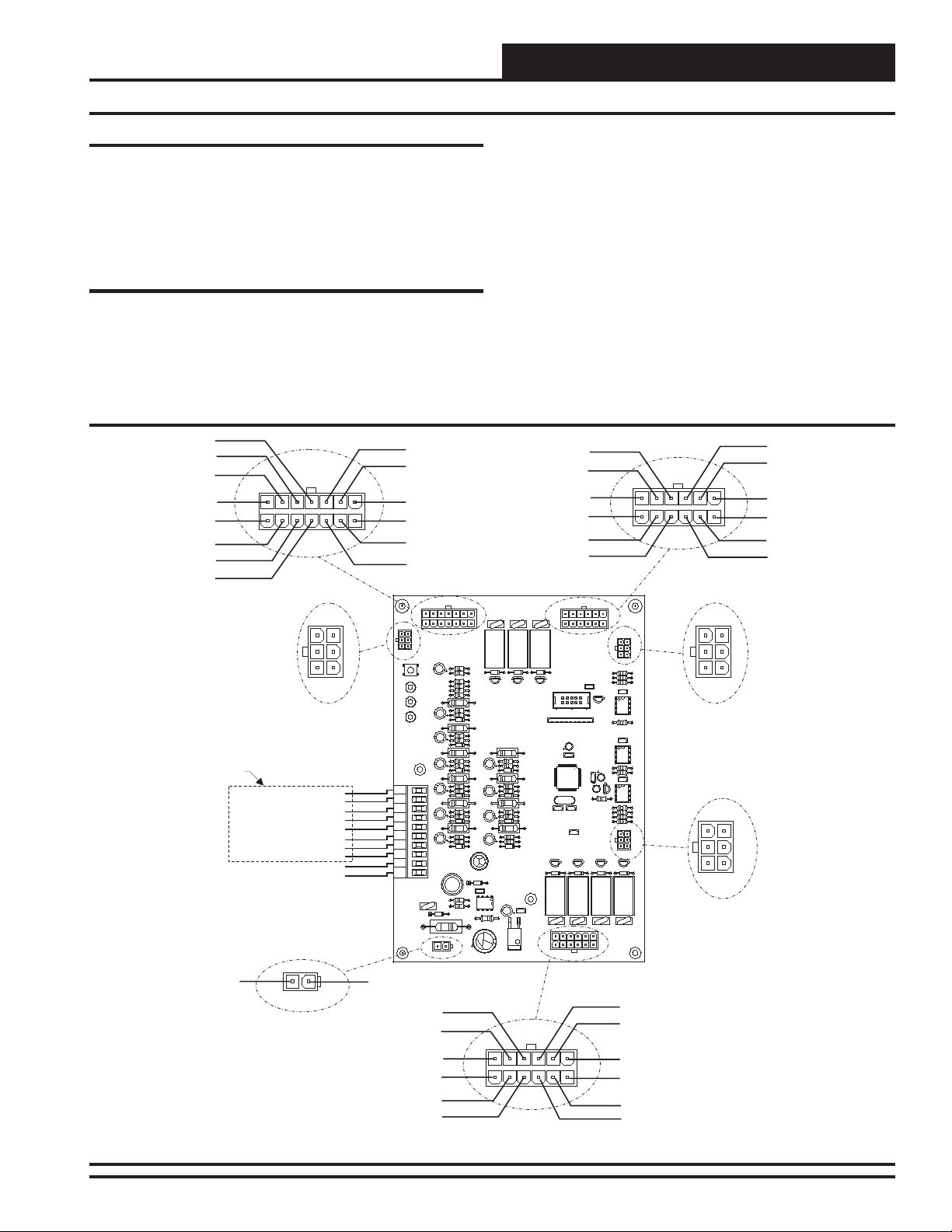
Controller Installation & Wiring
Technical Guide
Controller Mounting
It is important to mount the controller in a location that is free from
extreme high or low temperatures, moisture, dust and dirt. Be careful
not to damage the electronic components when mounting the controller. The HB Mini Controller mounts in the HB unit control panel using
the 4 plastic standoffs located on the HB control enclosure mounting
base.
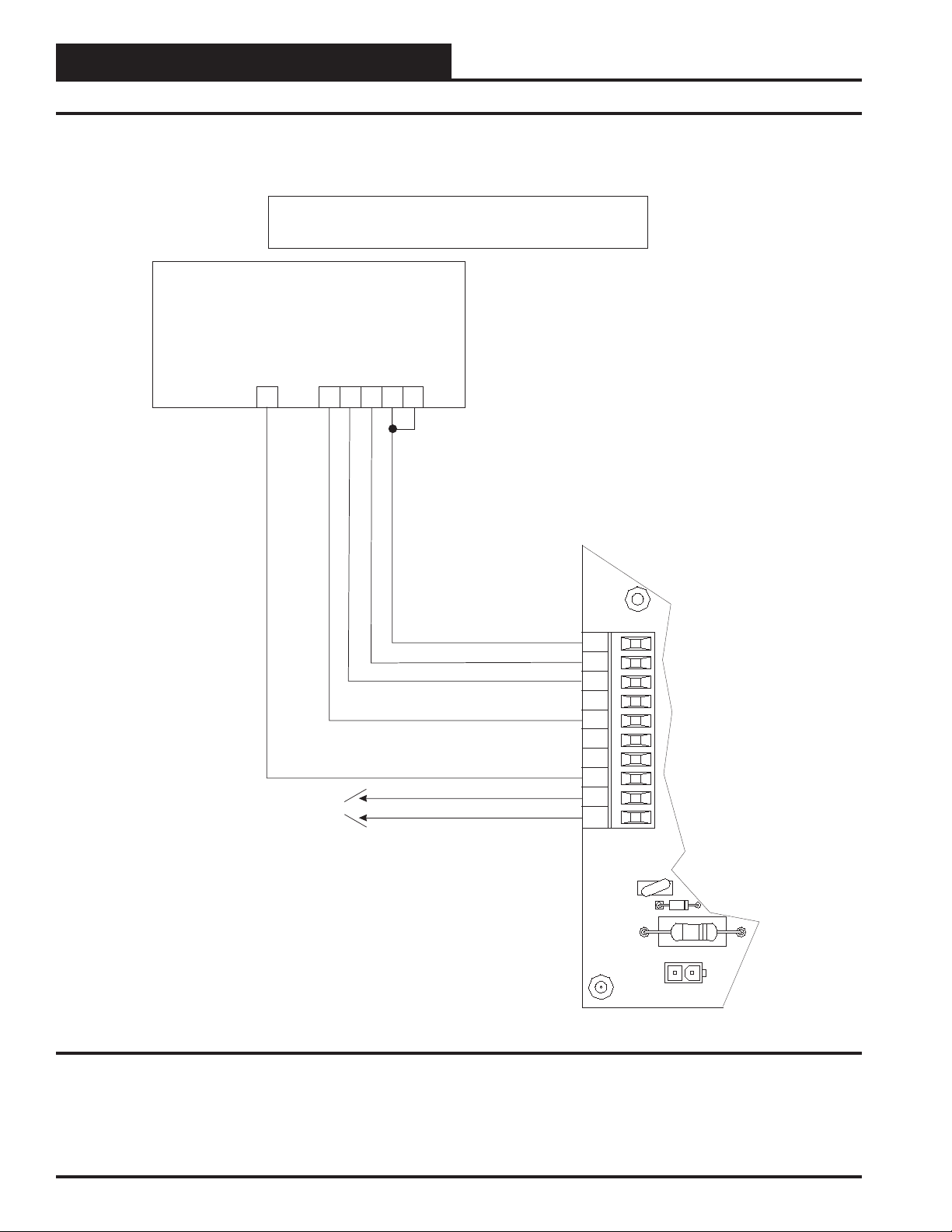
Important Wiring Considerations
Please carefully read and apply the following information when wiring
the HB Mini Controller.
1. All 24 VAC wiring must be connected so that all ground
wires remain common. Failure to follow this procedure
can result in damage to the controller and connected
devices.
PIN11 - 24 VAC
PIN12 - RAB
PIN13 - CO2
PIN14 - GND
PIN7-24VAC
PIN6 - GND
PIN5 - OAT
PIN4-24VAC
HIGH SPEED
SERIAL
COMMUNICATIONS
CONNECTOR
See Thermostat
Wiring Diagrams
For Complete Wiring
Connection Details
(C1) CLOGGED FILTER SWITCH 24 VAC OUTPUT
(C2) CLOGGED FILTER SWITCH 24 VAC OUTPUT
PIN2-24VAC
Figure 2: HB Mini Controller Wiring
ECONO SECTION
P1
P8
(R) FROM THERMOSTAT
(C) FROM THERMOSTAT
(G) FROM THERMOSTAT
(Y1) FROM THERMOSTAT
(Y2) FROM THERMOSTAT
(W1) FROM THERMOSTAT
(W2) FROM THERMOSTAT
(W3) FROM THERMOSTAT
24VAC
GND
P10
HSS
(GND)
PIN1 - GND
PIN10 - HPS
PIN11 - LO_SPD
PIN12 - FAN
PIN6 - COND
PIN5 - GND
PIN4 - LL_TMP
PIN10 - GND
PIN9 - ECONO POS
PIN8 - CFS
PIN1 - SW_24VAC
PIN2 - GND
PIN3 - SPARE IN
ECONO SECTION
P1
HSS
P8
C3
SW1
R71
LD1 LD2 LD3
R27
R34
R40
C1
C12
C15
C19
R
C
C25
G
Y1
Y2
C27
W1
W2
W3
C1
C2
L1
TB3
V10
R66
R67
D23
24VAC
GND
P10
C29
R69
C33
2. All wiring is to be in accordance with local and national
3. Minimum wire size for 24 VAC thermostat wiring should
4. Minimum wire size for all sensors should be 24 gauge.
5. Be sure that all wiring connections are properly inserted
6. Be sure all modular wiring harness connectors are seated
PIN10 - COM_23
PIN11 - COM_23
PIN12 - GND
PIN6 - COM_1
PIN5 - HEAT_1
PIN4 - GND
V1
K2
R12
D20
D21
R10
R1
R2
R3
D5
R24
R26
R28
D8
R35
R37
R38
D10
R43
C18
R45
R47
D12
R52
C22
R54
R55
D14
R59
C28
R62
R64
D15
C30
D22
R68
P4
D19
Q8
Q9
HB MINI
YS102032
REV 1
MADE INTHE USA
SERIAL#
R30
R32
R36
D9
C14
R41
R42
R44
D11
R49
R51
R53
D13
R60
R63
R65
D16
C32
C31
VR2
COOLING SECTION
electrical codes and specifications.
be 22 gauge.
and tightened into the terminal blocks. Do not allow wire
strands to stick out and touch adjoining terminals which
could potentially cause a short circuit.
firmly in their respective modular connectors on the HB
Mini circuit board.
V3
Q7
U4
X1
C23
Q4
K5
V5
P4
HEATSECTION
P9
K4
RN1
Q5
D4
V9
COOLING SECTION
HEAT SECTION
P9
P3
P3
HSS
R8
C37
P6
C38
C13
C40
C24
C41
D17
R11
R13
C5
U5
HSS
DRV
U1
C20
U6
C17
C39
R58
R61
VR1
C46
P-BUS
DRV
R4
R75
R72
R73
R74
P-BUS
P11
Q2
Q3
D3
D2
P11
V7
V8
PIN9 - LPS
PIN8 - COOL_1
PIN7 - COOL_2
PIN1 - GND
PIN2 - VFD
PIN3 - GND
PIN9 - HT_MON
PIN8 - HEAT_3
PIN7 - HEAT_2
PIN1 - HEAT_1
PIN2-24VAC
PIN3-24VAC
HIGH SPEED
HSS
SERIAL
COMMUNICATIONS
CONNECTOR
P-BUS
PERIPHERAL BUS
CONNECTOR
HB Mini Controller
5
Page 6

Technical Guide
Controller Installation & Wiring
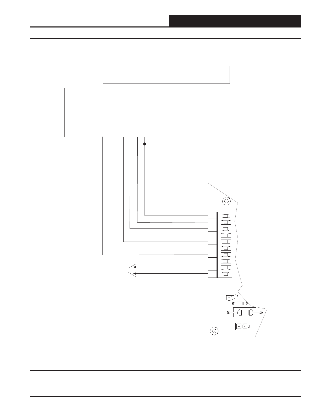
Single Stage T-stat Wiring For HB Unit
Single Stage T-stat Wiring For HB Units
With 1 Stage Cooling&1StageHeating
With 1 Stage Cooling&1StageHeating
Single-Stage Thermostat
1-Cool / 1-Heat
W1
Y1
Clogged Filter Indicator
(Outputs 24VAC)
(24VAC)
G
RC
C
RH
HB Mini Controller Terminal Block
(GND)
24VAC
GND
R
C
G
Y1
Y2
W1
W2
W3
C1
C2
TB3
V10
24VAC
P10
Figure 3: Single Stage T-stat Wiring For HB Unit With 1 Stage Cooling & 1 Stage Heating
6
HB Mini Controller
R69
GND
Page 7
Technical Guide
Single Stage T-stat Wiring For HB Unit
Single Stage T-stat Wiring For HB Units
With 1 Stage Cooling&1StageHeating
With 2 Stage Cooling&2StageHeating
Single-Stage Thermostat
1-Cool / 1-Heat
W1
Y1
Clogged Filter Indicator
(Outputs 24VAC)
(24VAC)
G
C
RC
RH
24VAC
GND
HB Mini Controller Terminal Block
(GND)
R
C
G
Y1
Y2
W1
W2
W3
C1
C2
TB3
V10
24VAC
P10
Figure 4: Single Stage T-stat Wiring For HB Units With 2 Stage Cooling & 2 Stage Heating
HB Mini Controller
R69
GND
7
Page 8
Technical Guide
Controller Installation & Wiring
Single Stage T-stat Wiring For HB Unit
Single Stage T-stat Wiring For HB Units
With 1 Stage Cooling&1StageHeating
With 2 Stage Cooling&3StageHeating
Single-Stage Thermostat
1-Cool / 1-Heat
W1
Y1
Clogged Filter Indicator
(Outputs 24VAC)
(24VAC)
G
C
RC
RH
24VAC
GND
HB Mini Controller Terminal Block
(GND)
R
C
G
Y1
Y2
W1
W2
W3
C1
C2
TB3
V10
24VAC
P10
Figure 5: Single Stage T-stat Wiring For HB Units With 2 Stage Cooling & 3 Stage Heating
8
HB Mini Controller
R69
GND
Page 9

Technical Guide
Single Stage T-stat Wiring For HB Unit
Multi-Stage T-stat Wiring For HB Units
With 1 Stage Cooling&1StageHeating
With 2 Stage Cooling&2StageHeating
Multi-Stage Thermostat
2-Cool / 2-Heat
W2
W1
Y1
Y2
Clogged Filter Indicator
(Outputs 24VAC)
(24VAC)
G
C
RC
RH
HB Mini Controller Terminal Block
(GND)
24VAC
GND
R
C
G
Y1
Y2
W1
W2
W3
C1
C2
TB3
V10
24VAC
P10
Figure 6: Multi Stage T-stat Wiring For HB Units With 2 Stage Cooling & 2 Stage Heating
HB Mini Controller
R69
GND
9
Page 10

Technical Guide
Controller Installation & Wiring
Single Stage T-stat Wiring For HB Unit
Multi-Stage T-stat Wiring For HB Units
With 1 Stage Cooling&1StageHeating
With 2 Stage Cooling&3StageHeating
Multi-Stage Thermostat
2-Cool / 3-Heat
W3
W2
W1
Y1
Y2
Clogged Filter Indicator
(Outputs 24VAC)
(24VAC)
G
C
RC
RH
24VAC
GND
HB Mini Controller Terminal Block
(GND)
R
C
G
Y1
Y2
W1
W2
W3
C1
C2
TB3
V10
24VAC
P10
Figure 7: Multi Stage T-stat Wiring For HB Units With 2 Stage Cooling & 3 Stage Heating
10
HB Mini Controller
R69
GND
Page 11

Programming With The HB Service Tool
Technical Guide
Entering Passcodes
The HB Service Tool is used to program setpoints and view the status
of the HB Mini Controller. It is connected to the HB Mini Controller by
means of a modular cable. The cable is connected between the HB
Service Tool and the HB Mini Controller board. The HB Service Tool
doesn’t require batteries or a separate power source as all power to
operate the HB Service Tool is provided through this cable. The HB
Mini Controller must be powered in order for the HB Service Tool to
function.
Device Address
064
When the HB Service T ool is initially powered up, the program version
and the current time and date will be displayed. After the initial power
up, this screen only appears when the HB power is removed and then
reapplied. Press ENTER and the HB Service T ool will check all current
parameters. When it has finished this checking procedure, press ENTER and the main HB programming screen will be displayed. If you
want to change setpoints you will need to enter a passcode at this time.
If you only want to view status, a passcode is not required and you can
proceed to view status directly by pressing the ENTER key.
The passcode entry screen uses a four digit alpha passcode. Position the
cursor under the first letter field. To select the desired letter, use the
ADJUST ARROWS. The UP arrow increases through the alphabet and
the DOWN arrow decreases. When the desired letter appears, press the
RIGHT ARROW key to advance to the next letter field. Once all four
letter fields spell the desired passcode, press the ENTER key.
Available passcodes are:
“OPER” = The Operator is at level 1 for Status and
Setpoints
“CONT” = The Contractor is at level 2 for Status, Setpoints
and Force Modes
Again, if no passcode is entered, the default level is 0 and only allows
viewing of the status screens.
General Procedures
When the HB Service Tool is initially powered up, this screen will be
displayed. Press ENTER to proceed to the next screen.
Version: X.XX
Date: XX/XX/XX
Enter your passcode as described in the previous section and proceed
by pressing the MENU key. The following screen will be displayed.
Device Address:
064
Line #2 displays the default address for the HB Mini Controller. Press
the ENTER key. The following screen will be displayed.
If you want to change the Passcode, hold down on the UP and DOWN
SELECT ARROWS simultaneously and the following screen will be
displayed.
Enter Code
AAAA
HB Mini Controller
Device Name
HBMini
Line #2 displays the controller name or program name. Press the ENTER key to advance.
Module Selection Screens
After pressing ENTER in the previous step, the first available programming module screen appears. All of the HB Mini Controller S tatus and
Setpoint Screens are grouped in specific modules designated by a specific function name.
Main Status
Fan Status
Using the select arrows, scroll to select the desired module on line #1
and press the ENTER key. The other available module screens are listed
below in order that they would appear as you scroll down.
11
Page 12

Technical Guide
Programming With The HB Service Tool
OAT Cool Lockout
Cooling Module
Heating Module
OAT Cool Lockout
NO
Alarms
HVAC Test
Factory Options
Factory Options should not be accessed without contacting AAON® or
WattMaster.
Warning: The Factory Options settings should only be accessed
when authorized by AAON
Support personnel. Serious damage to the controller
and/or HVAC unit could result from improper use of
these settings.
®
or W attMaster Technical
HB Mini Controller Status & Setpoints
The Status and Setpoint screens for the various modules are accessed
by selecting a specific module and pressing the ENTER key.
Main Status Screens
The Main Status Screen is accessed by selecting the Main Status Module and pressing the ENTER key. This screen, as its name indicates,
allows the user to view the Main Status screens for the HB Mini Controller. After the ENTER key is pressed, the following screen will be
displayed.
HVAC Mode
HVAC Mode
Idle
Line #2 displays “YES” if the Outdoor Air Temperature is below the
Cooling Lockout Temperature Setpoint.
OAT Temperature
OAT
XXX F
Line #2 displays the current Outdoor Air Temperature.
Alarms
Alarms
NO
Line #2 displays “YES” if an alarm is active. To identify the active
alarm(s), press the ESC key, select the Alarm Module and scroll through
the available alarms using the up and down SELECT arrow keys.
Program Date
Program Date
XX/XX/XX
Line #2 displays the Month/Day/Year that the HB Mini Controller
software was created.
Program Time
Program Time
XX:XX:XX
Line #2 displays one of the following HVAC Modes:
• Idle • Venting
• Cooling • Fault
• Heating
Press the down SELECT arrow key or up SELECT arrow key to move
forward or backward through the Main Status screens as desired.
OAT Heat Lockout
OAT Heat Lockout
NO
Line #2 displays “YES” if the Outdoor Air Temperature is above the
Heating Lockout Temperature Setpoint.
12
Line #2 displays the time, in 24-hour (military) format that the HB
Mini Controller software was created .
Program Version
Program Version
X.XX
Line #2 displays the HB Mini Controller software version number.
.
HB Mini Controller
Page 13

Technical Guide
Reset Counts
Reset Count
XXXX
Line #2 displays the total number of times the HB Mini Controller has
been reset or has had its power cycled.
Fan Module Status Screens
The Fan Module Status Screens are accessed by navigating to the Fan
Module and pressing the ENTER key.
Fan Terminal Active
G-Active
NO
Line #2 displays “YES” if there is a 24 VAC signal connected to the
“G” Fan terminal on the HB Mini Controller.
High Speed Fan Relay
High Fan Relay
OFF
Cooling Stage 1 Energized
Y1-Active
NO
Line #2 displays “YES” if there is a 24 VAC signal on HB Mini Controller terminal “Y1”.
Cooling Stage 2 Energized
Y2-Active
NO
Line #2 displays “YES” if there is a 24 VAC signal on HB Mini Controller terminal “Y2”.
Fan Status
Fan Status
Fan Off
Line #2 displays the current Supply Fan Status. If the Supply Fan is
on, line #2 displays either “Fan Low Speed” or “Fan High Speed”.
Line #2 displays “ON” if the High Speed Fan Relay is active.
Low Speed Fan Relay
Low Fan Relay
OFF
Line #2 displays “ON” if the Low Speed Fan Relay is active.
Cooling Module Status Screens
The Cooling Module Status Screens are accessed by navigating to the
Cooling Module screen and pressing the ENTER key. The following
screen will then appear.
Status
Setpoints
Select “Status” by pressing the ENTER key. Press the up or down SELECT arrow key to move forward or backward through the Cooling
Module Status screens.
Cooling Relay #1
Cool 1 Relay
OFF
Line #2 displays “ON” if Cooling Relay #1 is active.
Cooling Relay #2
Cool 2 Relay
OFF
Line #2 displays “ON” if Cooling Relay #2 is active.
Low Pressure Switch
LPS
OPEN
Line #2 displays the current status of the Low Pressure Switch. It will
only display “CLOSED” when Cooling Relay #1 relay is active and
the Low Pressure Switch is operating correctly.
HB Mini Controller
13
Page 14

Technical Guide
Programming With The HB Service Tool
High Pressure Switch
HPS
OPEN
Line #2 displays the current status of the High Pressure Switch. It
will only display “CLOSED” when Cooling Relay #1 relay is active
and the High Pressure Switch is operating correctly.
Cooling Module Setpoint Screens
The Cooling Module Setpoints Screens are accessed by navigating to
the Cooling Module screen and then pressing the ENTER key. The following screen will then appear.
Status
Setpoints
Press the down SELECT arrow key until “Setpoints” is on the top line
of the screen and then press the ENTER key. Press the down SELECT
arrow key or up SELECT arrow key to move forward or backward
through the Cooling Module Setpoint screens.
Please see the Appendix section in the back of this manual for Tables
listing the minimum, maximum and default setpoints for all of the
setpoint screens.
Cooling Stages Quantity
Cool Stages
X
Cooling Minimum On Time
Cool Min On
XXX Sec
Adjust the desired Cooling Minimum On Time and then press the ENTER key.
Cooling Stage Up Delay
Cool Stage Up
XXX Sec
Adjust the desired Cooling Stage Up Delay time and then press the
ENTER key.
Cooling Stage Down Delay
Cool Stage Down
XXX Sec
Adjust the desired Cooling Stage Down Delay time and then press the
ENTER key.
Low Pressure Switch Delay
LPS Delay
XXX Sec
Adjust the quantity of Cooling Stages or Steps of Cooling and then
press the ENTER key.
Outdoor Air Temperature Cooling Lockout
OAT Cool Lockout
XXX F
Adjust the Outdoor Air Temperature Cooling Lockout and then press
the ENTER key.
Cooling Minimum Off Time
Cool Min Off
XXX Sec
Adjust the desired Cooling Minimum Off Time and then press the
ENTER key.
The Low Pressure Switch Delay time is a factory setting and should not
be changed unless authorized to do so by W attMaster or AAON® T echnical Support.
Low Pressure Switch Safety Delay
LPS Safety
XX Sec
The Low Pressure Switch Safety Delay time is a factory setting and
should not be changed unless authorized to do so by WattMaster or
AAON® Technical Support.
LPS Maximum Trips
LPS Max trips
XX
The Low Pressure Switch Max Trips is a factory setting and should not
be changed unless authorized to do so by W attMaster or AAON® T echnical Support.
14
HB Mini Controller
Page 15

Technical Guide
Cooling Fan Off Delay
Cool Fan Off Dly
XXX Sec
The Cooling Fan Off Delay is a factory setting and should not be
changed unless authorized to do so by WattMaster or AAON
cal Support.
®
Techni-
Auto Stage Up Time
Auto Stage Up
XXX Sec
The Auto Stage Up Time can be adjusted on this screen when you are
using a single-stage thermostat with a multi-stage HB unit.
Heating Module Status Screens
The Heating Module Status Screens are accessed by navigating to the
Heating Module screen and pressing the ENTER key. The following
screen will then appear.
Heating Stage 3 Energized
W3-Active
NO
Line #2 displays “YES” if there is a 24 VAC signal on HB Mini Controller terminal “W3”.
Fan Status
Fan Status
Fan Off
Line #2 displays the current Supply Fan Status. If the Supply Fan is
on, line #2 displays either “Fan Low Speed” or “Fan High Speed”.
Heating Relay #1
Heat 1 Relay
OFF
Line #2 displays “ON” if Heating Relay #1 is active.
Status
Setpoints
Select “Status” by pressing the ENTER key. Press the up or down SELECT arrow key to move forward or backward through the Heating
Module Status screens.
Heating Stage 1 Energized
W1-Active
NO
Line #2 displays “YES” if there is a 24 VAC signal on HB Mini Controller terminal “W1”.
Heating Stage 2 Energized
W2-Active
NO
Line #2 displays “YES” if there is a 24 VAC signal on HB Mini Controller terminal “W2”.
Heating Relay #2
Heat 2 Relay
OFF
Line #2 displays “ON” if Heating Relay #2 is active.
Heating Relay #3
Heat 3 Relay
OFF
Line #2 displays “ON” if Heating Relay #3 is active.
Heat Safety Monitor
HSM
CLOSED
Line #2 displays “OPEN” anytime the Heat Safety Monitor is open.
HB Mini Controller
15
Page 16

Technical Guide
Programming With The HB Service Tool
Heating Module Setpoint Screens
The Heating Module Setpoints Screens are accessed by navigating to
the Heating Module and then pressing the ENTER key. The following
screen will then appear.
Status
Setpoints
Press the down SELECT arrow key until “Setpoints” is on the top line
of the screen and then press the ENTER key. Press the down SELECT
arrow key or up SELECT arrow key to move forward or backward
through the Heating Module Setpoint screens.
Please see the Appendix section in the back of this manual for Tables
listing the minimum, maximum and default setpoints for all of the
setpoint screens.
Heating Stages Quantity
Heat Stages
X
Adjust the quantity of Heating Stages and then press the ENTER key.
Outdoor Air Temperature Heating Lockout
OAT Heat Lockout
XXX F
Heating Stage Up Delay
Heat Stage Up
XXX Sec
Adjust the desired Heating Stage Up Delay time and then press the
ENTER key.
Heating Stage Down Delay
Heat Stage Down
XXX Sec
Adjust the desired Heating Stage Down Delay time and then press the
ENTER key.
Heat Safety Monitor Maximum Trips
HSM Max Trips
X
The Heating Safety Maximum Trips is a factory setting and should not
be changed unless authorized to do so by W attMaster or AAON
nical Support.
®
Tech-
Heating Fan Off Delay
Heat Fan Off Dly
XXX Sec
Adjust the Outdoor Air Temperature Heating Lockout and then press
the ENTER key.
Heating Minimum Off Time
Heat Min Off
XXX Sec
Adjust the desired Heating Minimum Off Time and then press the
ENTER key.
Heating Minimum On Time
Heat Min On
XXX Sec
Adjust the desired Heating Minimum On Time and then press the ENTER key.
The Heating Fan Off Delay is a factory setting and should not be changed
unless authorized to do so by WattMaster or AAON® Technical Support.
Auto Stage Up Time
Auto Stage Up
XXX Sec
The Auto Stage Up Time can be adjusted on this screen when you are
using a single-stage thermostat with a multi-stage HB unit.
Alarm Module Status Screens
The Alarm Module Status Screens are accessed by navigating to the
Alarm Module and pressing the ENTER key. Setpoints are not available for the Alarm Module. After pressing ENTER the following screen
will appear.
16
HB Mini Controller
Page 17

Technical Guide
HSM Lockout
HSM Lockout
NO
Line #2 displays “YES” when the Heat Safety Monitor has tripped more
than the HSM Max Trips setpoint.
HPS Fault
HPS Fault
NO
Line #2 displays “YES” when the High Pressure Switch is open and
a Cooling Relay is active.
LPS Lockout
LPS Lockout
NO
Line #2 displays “YES” when the Low Pressure Switch has tripped
more than the LPS Max Trips setpoint.
Bad OAT Sensor
Clogged Filter
Clogged Filter
NO
Line #2 displays “YES” if there is a 24 VAC signal on the Clogged
Filter Input.
HVAC Test Module Screens
The HV AC Test Module screens are accessed by navigating to the HV AC
Test Module screen and pressing the ENTER key. After pressing ENTER the following screen will then appear.
Force Time Limit
Force Time Limit
XXX Min
Adjust the desired time needed for forcing the HB Mini Controller
into an HVAC Test Mode and then press the ENTER key.
Force Relays
Force Relays
NO
Bad OAT
NO
Line #2 displays “YES” when the Outdoor Air Temperature Sensor is
bad or missing.
OAT Cooling Lockout
OAT Cool Lockout
NO
Line #2 displays “YES” if the Outdoor Air Temperature is below the
Cooling Lockout Temperature setpoint.
OAT Heating Lockout
OAT Heat Lockout
NO
Line #2 displays “YES” if the Outdoor Air Temperature is above the
Heating Lockout Temperature setpoint.
Select “YES” to enable Relay Force Mode and then press the ENTER
key.
High Speed Fan Relay Force
HSpd Fan Relay
OFF
Select “YES” to activate the High Speed Supply Fan Relay and then
press the ENTER key.
Low Speed Fan Relay Force
LSpd Fan Relay
OFF
Select “YES” to activate the Low Speed Supply Fan Relay and then
press the ENTER key.
HB Mini Controller
17
Page 18
Technical Guide
Programming With The HB Service Tool
Cooling Relay #1 Force
Cool 1 Relay
OFF
Select “YES” to activate Cooling Relay #1 and then press the ENTER
key.
Cooling Relay #2 Force
Cool 2 Relay
OFF
Select “YES” to activate Cooling Relay #2 and then press the ENTER
key.
Heating Relay #1 Force
Heat 1 Relay
OFF
Select “YES” to activate Heating Relay #1 and then press the ENTER
key.
Heating Relay #2 Force
Heat 2 Relay
OFF
Select “YES” to activate Heating Relay #2 and then press the ENTER
key.
Heating Relay #3 Force
Heat 3 Relay
OFF
Select “YES” to activate Heating Relay #3 and then press the ENTER
key.
18
HB Mini Controller
Page 19

Troubleshooting
Technical Guide
Using LEDs To Verify Operation
The HB Mini Controller is equipped with LEDs that can be used as
very powerful troubleshooting tools. The HB Mini Controller circuit
board has three different colored LEDs. See Figure 8 for the various
LED locations. The Red LED is used to indicate fault conditions. The
Y ellow LED indicates the mode of operation the HB Mini Controller is
currently operating in. The Green LED indicates the power and communications status of the HB Mini Controller.
MHGRV
RESET
ECONO
POS
RAB
LD1 - Red LED
LD2 - Yellow LED
LD3 - Green LED
GND
TB2
LD1
LD2
LD3
TB1
SAT
GND
HB Mini Controller Fault Condition Operation
If the Red LED indicates you have a Bad Outdoor Air Temperature
Sensor, heating mode will operate but Cooling Mode will be disabled
until the sensor problem is fixed.
Yellow LED
LED Blinks Mode Indication Description
1 Vent Mo de (Fan O nly)
2 Heating Mode
3 Coo ling M o de
Table 2: Yellow LED Blink Codes
Green LED
LED Blinks Power/Communications Description
1 Power Indi cator (No Communications)
2 HSS Communications
Table 3: Green LED Blink Codes
HB Controller Board
Figure 8: HB Board LED Locations
One LED blink is defined as a 1 second LED on period immediately
followed by a 1 second LED off period. After each series of blinks is
completed the LED will power off for 3 seconds and then repeat the
series of blinks. The various blink codes and their meanings are defined
in the tables that follow.
Red LED
LED Blinks Fault Condition Description
1 Hea t Safety Loc k o u t
2 High Pressure Fault
3 Low Pressure L ock out
5 Bad Outdoor Air Tem perature Sensor
7 Clog ged Filter Sw itch
Notes:
1.) W h e n n o f a u lt e xists the red LED will b e o f f .
2.) Heat Safety Lockout (1 blink) is the highest priority. Clogged
Filter S witch (7 blinks) is the lowest priority.
Table 1: Red LED Blink Codes
HB Mini Controller
19
Page 20

Technical Guide
Appendix
The HB Mini Controller has many setpoints that are user adjustable.
This adjustability allows the installer complete control of all major unit
operating characteristics during the setup and commissioning phase of
the HB unit installation. It also allows a service technician the ability to
change setpoints to monitor and record unit operation to determine if
the unit is functioning as specified. The tables that follow show the
available setpoints for each classification or control group provided on
the HB Mini Controller.
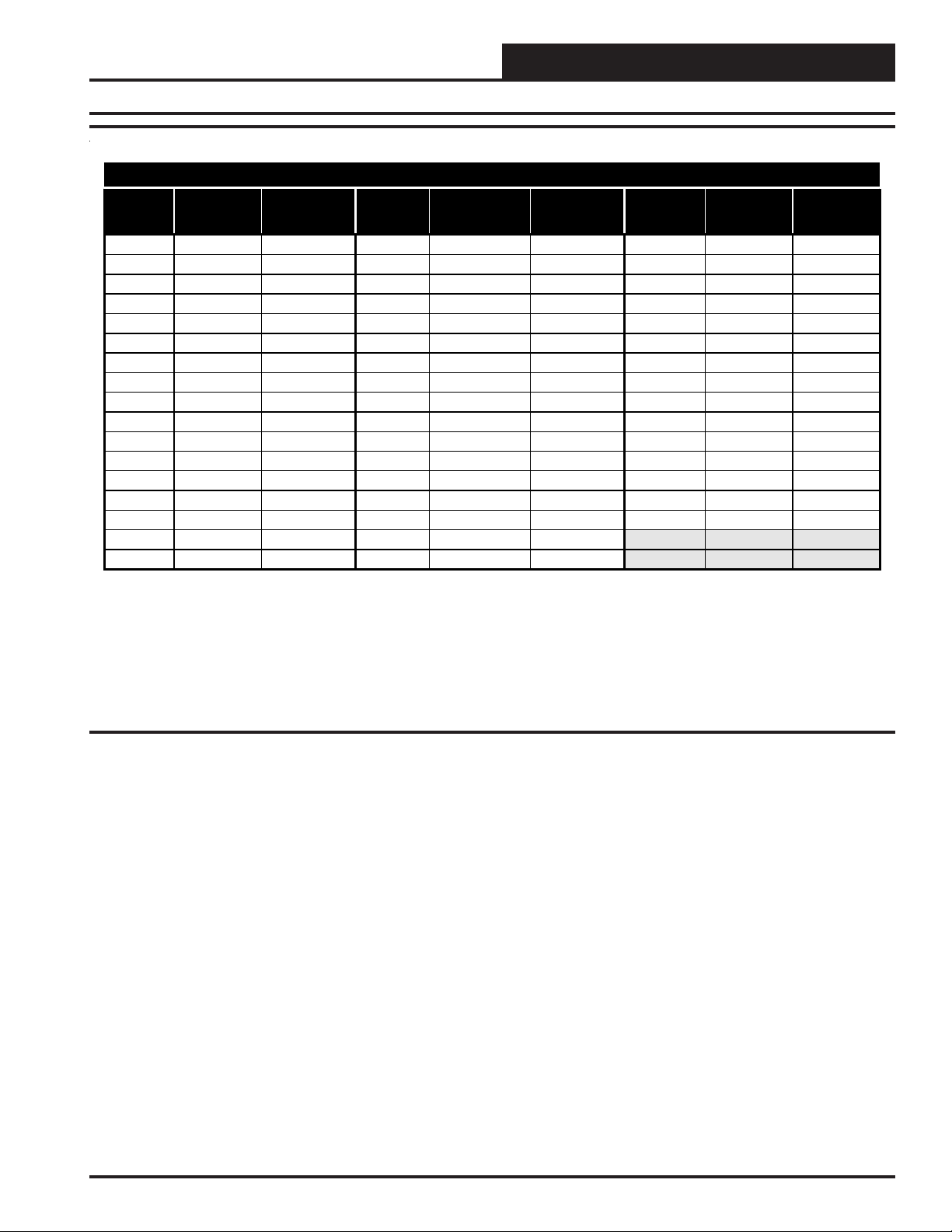
Temperature Control Setpoints
Description Min. Default Max.
Cooling Lockout
Temperature
Heating Lockout
Temperature
32° F 40° F 80° F
40° F 80° F 120° F
Cooling Control Setpoints
Description Min. Default Max.
Coolin g Stages 1 2 2
Minimum Off Time 180 Sec 180 Sec 900 Sec
Minimum On Time 300 Sec 300 Sec 900 Sec
Staging Up Delay Interval 180 Sec 180 Sec 900 Sec
Staging Down Delay Interval 60 Sec 60 Sec 900 Sec
Low Pressure Delay Period 5 Sec 30 Sec 60 Sec
Low Pressure Safety 5 Sec 5 Sec 30 Sec
Low Pressure Max. Trip Point 1 3 5
Fan Off Delay Period 1 Sec 45 Sec 120 Sec
Auto Staging Up Delay 180 Sec 600 Sec 900 Sec
Table 4: Cooling Control Setpoints
Heating Control Setpoints
Description Min. Default Max.
Heating Stages 1 3 3
Minimum Off Time 60 Sec 60 Sec 900 Sec
Minimum On Time 120 Sec 120 Sec 900 Sec
Staging Up Delay Interval 180 Sec 180 Sec 900 Sec
Staging Down Delay Interval 60 Sec 60 Sec 900 Sec
Heat Safety Maximum Count 1 3 5
Fan Off Delay Period 1 Sec 120 Sec 180 Sec
Auto Stage Up Delay 180 Sec 600 Sec 900 Sec
Table 6: Temperature Control Setpoints
Miscellaneous Control Setpoints
Description Min. Default Max.
Force Mode Timer 1 Min 60 Min 240 Min
Table 7: Miscellaneous Control Setpoints
Table 5: Heating Control Setpoints
20
HB Mini Controller
Page 21
Technical Guide
Temperature – Resistance – Voltage For Type III 10 K Ohm Thermistor Sensors
Temp
(ºF)
-10 93333 2.98 60 14681 1.96 86 8153 1.48
-5 80531 2.94 62 14014 1.93 88 7805 1.45
10 52500 2.77 68 12191 1.81 100 6047 1.24
15 45902 2.71 69 11906 1.79 105 5453 1.16
20 40147 2.64 70 11652 1.78 110 4923 1.09
25 35165 2.57 71 11379 1.76 115 4449 1.02
30 30805 2.49 72 11136 1.74 120 4030 0.95
35 27140 2.41 73 10878 1.72 125 3656 0.88
40 23874 2.33 74 10625 1.70 130 3317 0.82
45 21094 2.24 75 10398 1.68 135 3015 0.76
50 18655 2.15 76 10158 1.66 140 2743 0.71
52 17799 2.11 78 9711 1.63 145 2502 0.66
54 16956 2.08 80 9302 1.59 150 2288 0.61
56 16164 2.04 82 8893 1.55
58 15385 2.00 84 8514 1.52
Resistance
(Ohms)
0 69822 2.89 64 13382 1.89 90 7472 1.41
5 60552 2.83 66 12758 1.85 95 6716 1.33
Voltage @
Input (VDC)
Temp
(ºF)
Resistance
(Ohms)
Voltage @
Input (VDC)
Temp
(ºF)
Resistance
(Ohms)
Voltage @
Input (VDC)
Thermistor Sensor Testing Instructions
1.) Use the resistance column to check the thermistor sensor while disconnected from the controllers (not powered).
2.) Use the voltage column to check sensors while connected to powered controllers. Read voltage with meter set on DC volts. Place
the “-”(minus) lead on GND terminal and the “+”(plus) lead on the sensor input terminal being investigated.
If the voltage is above 3.3 VDC, then the sensor or wiring is “open.” If the voltage is less than 0.05 VDC, the sensor or wiring is shorted.
Table 8: Temperature Sensor - Voltage & Resistance for Type III Sensors
HB Mini Controller
21
Page 22

Notes:
Technical Guide
22
HB Mini Controller
Page 23

Technical Guide
HB Mini Controller
23
Page 24

AAON, Inc.
Form: AA-HBM-TGD-01A Printed in the USA November 2005
All rights reserved Copyright 2005
WattMaster Controls Inc. • 8500 NW River Park Drive • Parkville, Mo. • 64152
Phone (816) 505-1100 www.wattmaster.com Fax (816) 505-1101
2425 So. Yukon Ave • Tulsa, OK 74107-2728
Ph: (918) 583-2266 • Fax: (918) 583-6094
AAON® Part No. R38860
 Loading...