

Page 1
HB Controller
Technical Guide
Page 2

Table of Contents
Controller Overview ......................................................................................................................................... 3
General ........................................................................................................................................................................................3
Inputs ...........................................................................................................................................................................................3
Outputs ........................................................................................................................................................................................3
Controller Sequence of Operation .................................................................................................................. 4
Fan Mode .....................................................................................................................................................................................4
Heating Mode ..............................................................................................................................................................................4
Cooling Mode ..............................................................................................................................................................................4
Economizer Cooling ...................................................................................................................................................................4
General Economizer Operation.............................................................................................................................................4
Economizer Operation with ECS Control ............................................................................................................................. 4
Mechanical Cooling Staging with ECS Control .....................................................................................................................4
Economizer IAQ Control ...........................................................................................................................................................4
Economizer Dehumidifi cation ...................................................................................................................................................4
1-or 2-Stage Cooling Units with Adjustable Two-Speed or Two-Speed Supply Fan Control ................................................4
Dehumidifi cation Mode (No Reheat) .........................................................................................................................................5
Dehumidifi cation Mode with Hot-Gas Reheat ..........................................................................................................................5
1-Stage Cooling with Adjustable Two-Speed or Two-Speed Supply Fan Control ................................................................. 5
2-Stage Cooling with Adjustable Two-Speed or Two-Speed Supply Fan Control ................................................................ 5
Lockout Modes ...........................................................................................................................................................................5
SAT Lockout Modes ...................................................................................................................................................................6
Exhaust Fan Control .................................................................................................................................................................. 6
HB Processor Board .................................................................................................................................................................. 6
Controller Installation & Wiring ...................................................................................................................... 7
Programming with the HB Service Tool ........................................................................................................ 14
Optional MHGRV Module Settings ................................................................................................................. 34
Troubleshooting ............................................................................................................................................. 36
Appendix ........................................................................................................................................................ 37
Index .............................................................................................................................................................. 42
Space Temperature Control Sequence ................................................................................................................................. 6
Controller Mounting ...................................................................................................................................................................7
Important Wiring Considerations .............................................................................................................................................7
Entering Passcodes .................................................................................................................................................................14
General Procedures ................................................................................................................................................................. 14
Module Selection Screens ..................................................................................................................................................14
HB Controller Status & Setpoints ..........................................................................................................................................15
Main Status Screens ...........................................................................................................................................................15
Fan Module Status Screens ................................................................................................................................................16
Fan Module Setpoint Screens .............................................................................................................................................16
Cooling Module Status Screens ..........................................................................................................................................17
Cooling Module Setpoint Screens .......................................................................................................................................18
Heating Module Status Screens..........................................................................................................................................19
Heating Module Setpoint Screens.......................................................................................................................................20
Economizer Module Status Screens ................................................................................................................................... 21
Economizer Module Setpoint Screens ................................................................................................................................ 22
Dehumidify Module Status Screens .................................................................................................................................... 23
Alarm Module Status Screens.............................................................................................................................................24
Force Mode Module Screens .............................................................................................................................................. 25
Force Mode Module Setpoint Screens ................................................................................................................................26
Factory Options Module Screens ................................................................................................
........................................27
HB Processor Board ................................................................................................................................................................ 28
HB Processor Board Status Screens .................................................................................................................................. 28
HB Processor Setpoint Screens..........................................................................................................................................29
HB Processor Week Schedule Module Screens .................................................................................................................30
HB Processor Real Time Clock Module Screens ................................................................................................................ 31
Hot Gas Reheat Controller ......................................................................................................................................................32
Hot Gas Reheat Status Screens ......................................................................................................................................... 32
Supply Air Temperature ...........................................................................................................................................................34
Supply Air Temperature Reset Limit ...................................................................................................................................... 34
Using LEDs To Verify Operation ............................................................................................................................................. 36
HB Controller Fault Condition Operation.............................................................................................................................36
WattMaster Controls, Inc.
8500 NW River Park Drive · Parkville , MO 64152
Toll Free Phone: 866-918-1100
PH: (816) 505-1100 · FAX: (816) 505-1101 · E-mail: mail@wattmaster.com
Visit our web site at www.wattmaster.com
Form: AA-HB-TGD-01E Copyright 2009 WattMaster Controls, Inc.
®
AAON
is a registered trademark of AAON, Inc., Tulsa, OK.
WattMaster Controls, Inc. assumes no responsibility for errors, or omissions.
This document is subject to change without notice.
Page 3
Overview
Controller Overview
General
The HB Controller is designed to work with a normal 24 VAC Thermostat
and Dehumidistat. Single or Multi-stage Thermostats can be used. When
a Single-Stage Thermostat is used, an auto-staging feature is built-in for
Multi-stage HB units. Fan speed can be adjusted for both high and low
speeds by way of an interface when the HB unit is equipped with an
adjustable speed controller. Dehumidifi cation is optimized by use of a
Return Air Bypass damper. Modulating Hot-Gas Reheat can be used to
reheat the Supply Air during Dehumidifi cation.
A CO2 sensor can be connected through the wiring harness when IAQ
control is desired. Also, two damper positions are available when using
Two-Speed Supply Fans, thus providing enhanced IAQ control.
The HB Controller also monitors equipment safeties, logs information,
and locks out the equipment in the event of multiple failures. All sensors are needed in order to provide all modes of operation. However, to
prevent a potential freeze condition, Heating Mode will still operate if
all sensors have failed or are missing.
Terminal block style connections are provided for fi eld wiring of the
Thermostat, Dehumidistat, and Supply Air Temperature Sensor wires.
All other inputs and outputs are connected via a wiring harness on the
HB unit. A list of all available inputs and outputs follows.
Inputs
G, Y1, Y2, W1, W2, W3
RH: Dehumidistat
SAT: Supply Air Temperature Sensor
MHGRV Reset: Modulating Hot-Gas Reheat Signal (0-10VDC)
RAB: Return Air Bypass Damper Actuator (by others)
ECS: (Enthalpy Changeover Switch)
Econo Pos: Economizer Control (by others)
Carbon Dioxide Sensor
Outdoor Air Temperature Sensor
Liquid Line Temperature Sensor (currently not used)
Heat Safety Monitor (monitors main and auxiliary limit thermostats)
High-Pressure Switch
Low-Pressure Switch
Clogged Filter Switch
Outputs
Supply Fan High-Speed Relay
Supply Fan Low-Speed Relay
Cool-1 Relay
Cool-2 Relay
Heat-1 Relay
Heat-2 Relay
Heat-3 Relay
Condenser Fan Relay
AUX: Currently used for an exhaust fan relay
Modulating Hot-Gas Reheat Signal (from HGR controller)
Adjustable Two-Speed Fan Signal (0-10VDC)
Return Air Bypass Damper Actuator (0-10VDC)
Economizer Damper Actuator (2-10VDC)
Modulating Hot-Gas Reheat Reset Signal (0-10 VDC)
A1, A2: Economizer 24 VAC Power Supply Jumper Terminals
C1, C2: Clogged Filter Switch 24 VAC Output Terminals
PBS
P11
HEATSECTION
PROGRAM
SOCKET
P
V3
V2
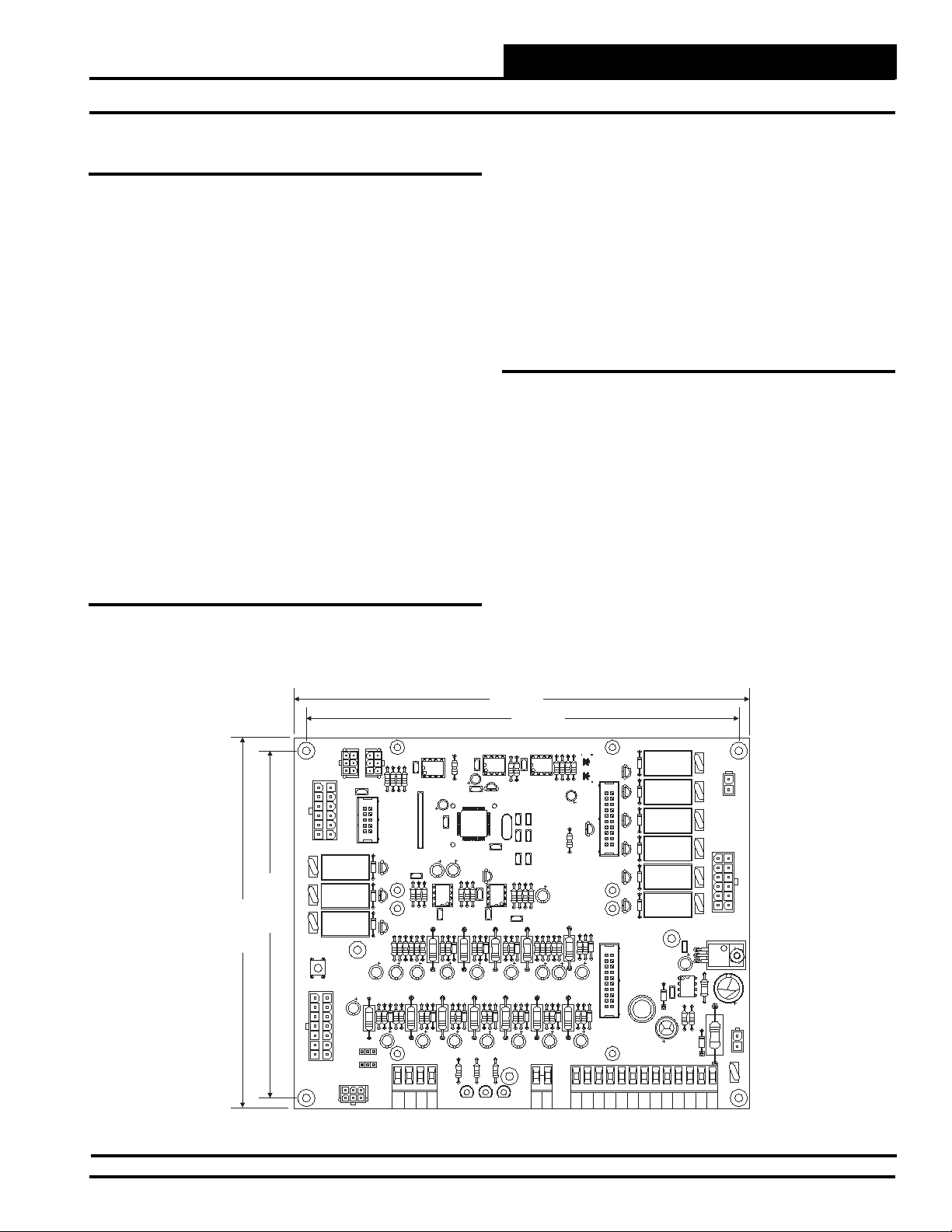
6.10"
V1
6.50
SW1
C1
ECONO SECTION
RAB
ECONO
P1
POS
P3
Figure 1: HB Controller Dimensions
8.00"
7.60"
HSS
R71
R11
R13
R8
P8
C5
C37
K4
D1
D21
D20
K2
C2
R1
D1
C4
JO2
JO1
INT
EXT
HSS
1
P6
RN1
7
7
C36
R21
R1
R16
8
R15
R18
R12
R7
R5
R10
C6
C3
R14
R17
R2
R3
D5
R6
R
C7
RAB
MHGRV
RESET
ECONO
POS
C20
R3
C3
C17
C38
C13
4
C43
C11
C8
R22
C10
R20
D6
GND
10
R31
R33
R2
2
C35
C
C16
R30
D7
R23
R25
D
R32
R36
C14
R24
R24
R35
R37
R28
D8
R26
R38
C12
C15
R40
R34
R27
TB2
LD2LD1
8
R74
R75
R72
6
R61
R58
5
C24
X1
C23
C41
R46
R70
3
C34
R41
R4
R42
R44
D11
C18
R43
R45
R47
D10
C1
LD3
R73
C46
C42
C44
C45
R48
C22
D12
TB1
TTL
C40
VR1
R4
R50
C21
R60
R63
R51
R53
R56
R57
D13
C28
C26
R52
R5
R62
R55
D14
R54
C27
C25
R
GND
SAT
D1
1
P7
D3
3
D2
AXCP
2
D18
6
D17
5
D4
4
R65
D16
R64
D15
GND
K5
C32
REV 4
YS101 2
7
D22
HB VB NIT BOARD
MADE IN THE SA
MOD HGR
P5
P5
RH
G
Y1
C2
L1
C30
Y2
W1
W2
W3
P2
V4
V8
V7
V6
V
V5
C31
MC34064A
36
R67
R66
A1
A2
AX
SERIAL #
SECTION
COOLING
P4
I
0
VR2
R68
C33
R6
GND
D23
P10
POWER
24VAC
V10
TB3
C2
C1
HB Controller Technical Guide
3
Page 4

Sequence of Operations
Controller Sequence of Operations
Fan Mode
The HB Controller supports 2 different Supply Fan confi gurations. It
can be confi gured for Adjustable Two-Speed Fan or Two-Speed Fan. On
a call for “G,” the Supply Fan runs at Low Speed. Minimum on and off
times are maintained in the event of a short cycled call for “G.”
Heating Mode
On a call for “W1,” the Supply Fan runs at High Speed (maintained
during the Heating mode), and Heat Stage 1 is energized. On a call for
“W2,” Heat Stage 2 is energized after the Stage-Up delay. If “W2” is
called without “W1,” Heat Stage 1 is energized, and then Heat Stage 2
is energized after the Auto Stage-Up Delay period. On a call for “W3,”
Heat Stage 3 is energized after the Stage-Up delay. If “W3” is called
without “W1” or “W2,” Heat Stages 1, 2, and 3 will energize based on
Auto Stage-Up Delays.
Cooling Mode
If the HB Controller is confi gured for 1 stage of Cooling, on a call for
“Y1,” the Supply Fan runs at High speed, and Cool Stage 1 will energize.
If the HB Controller is confi gured for 2 stages of Cooling, on a call for
“Y1,” the Supply Fan runs at Low Speed, and Cool Stage 1 is energized.
On a call for “Y2,” the Supply Fan runs at High Speed, and Cool Stage
2 is energized after the Stage-Up Delay. If “Y2” is called without “Y1,”
Cool Stage 1 is energized, and then Cool Stage 2 is energized after the
Auto Stage-Up Delay.
Economizer Cooling
General Economizer Operation
If the Outdoor Air Temperature is below the Economizer Enable Setpoint
and there is a call on “Y1,” the compressors will be locked out, and the
Economizer will modulate to achieve a 55° F Supply Air Temperature.
If the HB Controller is confi gured for 1 stage of Cooling, on a call for
“Y1,” the Supply Fan will run at High Speed. If the HB Controller is
confi gured for 2 stages of Cooling, on a call for “Y1,” the Supply Fan
will run at low speed. When “Y2” is called, the Supply Fan will go to
high speed.
Economizer Operation with ECS Control
If the Enthalpy Changeover Switch (ECS) is closed and the outdoor air
temperature is below the ECS, OAT Enable setpoint (default 65° F),
the economizer will modulate and attempt to achieve 55° F supply air
temperature. If the outdoor air temperature is above 55° F, the economizer will generally open to 100%. Mechanical cooling can be used
to supplement the economizer if the outdoor air temperature is above
the ECS OAT Enable setpoint and the economizer signal is at 100%.
Once mechanical cooling is activated to supplement the economizer, the
economizer will remain at 100% until the cooling call is satisfi ed.
Mechanical Cooling Staging with ECS Control
If the HB Controller is confi gured for 1 stage of Cooling, on a call for
“Y1,” the Supply Fan will run at High Speed. Cool Stage 1 will activate
after the Cooling Auto Stage-Up Delay. If the HB Controller is confi gured for 2 stages of Cooling, on a call for “Y1,” the Supply Fan will
run at Low Speed. Cool Stage 1 will activate after either the Cooling
Auto Stage-Up Delay Expires or a call for “Y2” is made. When “Y2”
is called, Cool Stage 2 will activate after the Cooling Auto Stage-Up
Delay. After Cool Stage 2 is activated, the Supply Fan will switch to
High-Speed operation.
Economizer IAQ Control
The economizer is also used for CO2 control. If the CO2 level is above
the Minimum CO2 PPM setpoint, the Economizer Minimum Position will
be reset proportionally between the Minimum CO2 PPM and Maximum
CO2 PPM setpoints. When the CO2 level is above the Maximum CO2
PPM setpoint, the Economizer will open as far as the Maximum Damper
Adjustment Position setpoint setting. There are two Minimum and two
Maximum Economizer Damper Positions depending on the Supply Fan
speed. These are the Maximum Damper Position with Low-Speed Fan,
the Minimum Damper Position with Low-Speed Fan, the Maximum
Damper Position with High-Speed Fan, and the Minimum Damper Position with High-Speed Fan. The air balancing contractor should determine
these settings in order to maintain the proper amount of fresh air being
supplied to the building.
Economizer Dehumidifi cation
1-or 2-Stage Cooling Units with Adjustable
Two-Speed or Two-Speed Supply Fan Control
If the Outdoor Air Temperature is below the Economizer Enable Setpoint
and there is a call for Dehumidifi cation on “RH,” the compressors will
be locked out, and the Economizer will modulate to achieve 55° F Supply Air Temperature. The Supply Fan will run at Low Speed, and the
Return Air Bypass will be closed.
For 1 stage Cooling units, on a call for “Y1,” the HB Controller will
enter the Cooling Mode, and the Supply Fan will run at High Speed. The
Cooling Mode will be maintained until “Y1” is satisfi ed. As long as there
is still a call for “RH,” the Dehumidifi cation Mode will resume.
For 2 stage Cooling Units, “Y1” is ignored during this mode to extend
Dehumidifi cation. On a call for “Y2,” the HB Controller will enter the
Cooling mode, and the Supply Fan will run at High Speed. The Cooling
Mode will be maintained until both “Y2” and “Y1” are satisfi ed. As long
as there is still a call for “RH,” the Dehumidifi cation Mode will resume,
and the Supply Fan will run at Low Speed.
If the HB Controller is confi gured for 1 stage of Heating, on a call for
“W1,” the mode changes to Heating. The Economizer will close to its
Minimum Position, Heat Stage 1 will energize, and the Supply Fan will
run at High Speed.
If the HB Controller is confi gured for 2 or 3 stages of Heating, on a call
for “W1,” the Economizer will be locked at its current position, attempting to deliver 55° F Supply Air to the heating section. Heat Stage 1 is
energized, and the Supply Fan will run on High speed. On a call for “W2,”
the HB Controller will enter the Heating Mode. The Economizer will
move to its Minimum Position, and Heat Stage 2 will energize after the
Stage-Up Delay. The Heating Mode will be maintained until both “W2”
and “W1” are satisfi ed. W3 is also available for 3 Stage Electric Heating
Units. As long as there is still a call for “RH,” the Dehumidifi cation Mode
will resume, and the Supply Fan will run at Low Speed.
4
HB Controller Technical Guide
Page 5

Sequence of Operations
Controller Sequence of Operations
Dehumidifi cation Mode (No Reheat)
Note: If the HB Controller is confi gured for 1 stage of Cooling,
regardless of the Supply Fan confi guration, the Dehumidifi cation call on “RH” is ignored during this mode.
On a call for “RH,” Cooling Stage 1 is energized and the Supply Fan
runs at Low Speed. The Return Air Bypass Damper will open to 100%.
“Y1” is ignored during this mode. On a call for “Y2,” the HB Controller
will enter the Cooling Mode, and the Supply Fan will run at High Speed.
The Cooling Mode will be maintained until both “Y2” and “Y1” are
satisfi ed. As long as there is still a call for “RH,” the Dehumidifi cation
Mode will resume, and the Supply Fan will run at Low Speed.
If the HB Controller is confi gured for 1 stage of Heating, on a call for
“W1,” the mode changes to Heating. Cool Stage 1 will de-energize, the
Return Air Bypass will close, Heat Stage 1 will energize, and the Supply
Fan will run at High Speed.
If the HB Controller is confi gured for 2 or 3 stages of Heating, a “W1”
call will be delayed to extend Dehumidifi cation. On a call for “W2,”
the HB Controller will enter the Heating Mode. Cool Stage 1 will deenergize, the Return Air Bypass will close, Heat Stage 1 will energize,
and the Supply Fan will run at High Speed. Heat Stage 2 will energize
after the Auto Stage-Up Delay. The Heating Mode will be maintained
until both “W2” and “W1” are satisfi ed. W3 is also available for 3Stage Electric Heating Units. As long as there is still a call for “RH,”
the Dehumidifi cation Mode will resume, and the Supply Fan will run
at Low Speed.
2-Stage Cooling with Adjustable Two-Speed or
Two-Speed Supply Fan Control
On a call for “RH,” Cool Stage 1 is energized, and the Supply Fan runs
at low speed. The Return Air Bypass is opened to 100%. The hot-gas
reheat will then modulate the valves to achieve the Supply Air setpoint
DIP switch setting. On a call for “Y1,” the Supply Air setpoint on the
reheat controller is lowered 10° F, and the Return Air Bypass will close.
On a call for “Y2,” the HB Controller will enter the Cooling Mode. The
Supply Fan will switch to high speed, and Cool Stage 2 is energized. The
modulating hot-gas reheat valves will move to the full Cooling position.
The Cooling mode will be maintained until both “Y2” and “Y1” are
satisfi ed. As long as there is still a call for “RH,” the dehumidifi cation
mode will resume.
If the HB Controller is confi gured for 1 stage of heating, on a call for
“W1,” the mode changes to Heating, and the Supply Fan will run at High
Speed. Cool Stage 1 will de-energize, the Return Air Bypass will close,
Heat Stage 1 will energize, and the Supply Fan will run at High Speed.
If the HB Controller is confi gured for 2 or 3 stages of Heating, on a call
for “W1,” the Supply Air Setpoint on the Reheat Controller is raised
10° F, and Cool Stage 1 continues to run. On a call for “W2,” the HB
Controller will enter the Heating Mode. Cool Stage 1 will de-energize,
the Return Air Bypass will close, Heat Stage 1 will energize, and the
Supply Fan will run at High Speed. Heat Stage 2 will energize after the
Auto Stage-Up Delay. The Heating Mode will be maintained until both
“W2” and “W1” are satisfi ed. W3 is also available for 3 Stage Electric
Heating Units. As long as there is still a call for “RH,” the Dehumidifi cation Mode will resume, and the Supply Fan will run at Low Speed.
Lockout Modes
Dehumidifi cation Mode with Hot-Gas
Reheat
1-Stage Cooling with Adjustable Two-Speed
or Two-Speed Supply Fan Control
On a call for “RH,” Cool Stage 1 is energized, and the Supply Fan
runs at High Speed. The Return Air Bypass is opened to 100%. The
Hot Gas Reheat will then modulate the valves to achieve the Supply
Air Setpoint DIP Switch setting. On a call for “Y1,” the HB Controller
enters the Cooling Mode. The Return Air Bypass will close, and the
Hot Gas Reheat will modulate to full Cooling. The Cooling Mode will
be maintained until “Y1” is satisfi ed. As long as there is still a call for
“RH,” the Dehumidifi cation Mode will resume.
If the HB Controller is confi gured for 1 stage of Heating, on a call for
“W1,” the mode changes to Heating, and the Supply Fan will run at
High Speed. Cool Stage 1 will de-energize, the Return Air Bypass will
close, Heat Stage 1 will energize, and the Supply Fan will run at High
Speed. If the HB Controller is confi gured for 2 or 3 Stages of Heating,
on a call for “W1,” the Supply Air Setpoint on the Reheat Controller
is raised 10° F, and Cool Stage 1 continues to run. On a call for “W2,”
the HB Controller will enter the Heating Mode. Cool Stage 1 will deenergize, the Return Air Bypass will close, Heat Stage 1 will energize,
and the Supply Fan will run at High Speed. Heat Stage 2 will energize
after the Auto Stage-Up Delay. The Heating Mode will be maintained
until both “W2” and “W1” are satisfi ed. W3 is also available for 3Stage Electric Heating Units. As long as there is still a call for “RH,”
the Dehumidifi cation Mode will resume.
Heating Mode is locked out if the HSM (Heat Safety Monitor) trips 3
times during a call for Heating. To reset the lockout condition, either
remove the call for Heating or cycle power to the HB Controller. Heating Mode is also locked out if the Outdoor Air Temperature is above the
OAT Heat Lockout setpoint temperature.
Cooling Mode is locked out if the LPS (Low Pressure Switch) trips 3
times during a call for Cooling or Dehumidifi cation. To reset the lockout
condition, either remove the call for Cooling or Dehumidifi cation or
cycle power to the HB Controller. Cooling Mode is also locked out if
the Outdoor Air Temperature is below the OAT Cool Lockout setpoint
temperature or if the OAT Sensor is bad or missing.
Economizer and Reheat during Dehumidifi cation modes are locked out
if the SAT sensor is missing.
Note: The Cooling OAT Lockout must be set less than the
Economizer Enable.
HB Controller Technical Guide
5
Page 6

Sequence of Operations
Controller Sequence of Operations
SAT Lockout Modes
Note: The SAT Lockout Modes only apply if a Supply Air
Temperature Sensor is installed on the HB unit.
SAT High Temperature Limit Cut Off Mode
During the Heating Mode, if the Supply Air Temperature rises above
the Supply Air High Temperature Limit Cut Off (150° F), the Heating
will stage off, but the main Supply Fan will remain on in Low-Speed
operation. If this occurs, the Supply Air Temperature must fall below
80° F in order for the Heating to stage back on. If this condition occurs 2 times consecutively during a Heating call, the HB Controller
will lockout in Supply Air High Temperature Limit Cut Off. To restore
normal operation, either remove the call for Heating or cycle power to
the HB Controller.
SAT Low Temperature Limit Cut Off Mode
During the Heating Mode, if the Supply Air Temperature falls below
the Supply Air Low Temperature Limit Cut Off (40° F), the Outdoor
Air Damper will close. If the Supply Air Temperature is still too cold
and remains there for 15 minutes, the Heating and the Supply Fan will
be turned off and locked out. This condition can only happen once, and
then the HB Controller will lockout in Supply Air Low Temperature
Limit Cut Off. To restore normal operation, either remove the call for
Heating or cycle power to the HB Controller.
Exhaust Fan Control
The Exhaust Fan is energized via the Auxiliary Relay. The Exhaust Fan
has two Economizer Position Activation points based on the Low- and
High-Speed Supply Fan condition. The air balancing contractor should
determine these settings for proper Building Pressure Control.
HB Processor Board
When the HB Controller has the optional HB Processor board installed,
a Space Temperature Sensor can be connected to it for HVAC Mode
Control. When the Space Temperature Sensor is used, the Push-Button
Override and Slide Adjust options are also available. Occupied and
Unoccupied Modes are available through week scheduling, force schedule, and a broadcast schedule. The HB Processor board also provides
communication with other HB controllers. Up to 60 other controllers
can be connected together via the RS-485 loop.
Space Temperature Control Sequence
When the Space Temperature Sensor is confi gured for control, Cooling
and Heating setpoints are used to activate the HVAC Modes of operation.
An HVAC Mode Deadband setpoint is used to determine the temperature
at which the Cooling and Heating Modes are activated above or below the
setpoints. Once in the Cooling Mode, the Space Temperature must drop
below the Cooling setpoint minus the deadband to enter the Vent Mode.
The same is true for the Heating mode; the Space Temperature must rise
above the Heating setpoint plus the deadband to enter the Vent Mode.
An additional Cooling Stage is activated for each 1° F rise of the Space
Temperature above the Cooling Setpoint up to the maximum number of
Cooling Stages available. In like manner, an additional Heating Stage is
activated for each 1° F drop of the Space Temperature below the Heating
Setpoint up to the maximum number of Heating Stages available.
When the Space Temperature rises above the Cooling setpoint plus the
deadband, the HB Controller enters the Cooling Mode, and Cooling Stage
1 is activated. Cooling Stage 2 is activated if the Space Temperature rises
by another 1° F above the Cooling setpoint. Cooling Stage 2 deactivates
when the Space Temperature drops below the Cooling setpoint. Cooling Stage 1 deactivates when the Space Temperature drops below the
Cooling setpoint minus the deadband.
When the Space Temperature drops below the Heating setpoint minus
the deadband, the HB Controller enters the Heating Mode, and Heating
Stage 1 is activated. Heating Stage 2 is activated if the Space Temperature
drops by 1° F. Heating Stage 3 is activated if the Space Temperature
drops by another 1° F below the Heating setpoint. Heating Stage 3 and
Heating Stage 2 both deactivate when the Space Temperature rises
above the Heating setpoint. Heating Stage 1 deactivates when the Space
Temperature rises above the Heating setpoint plus the deadband.
The Slide Adjust feature on the Space Temperature Sensors that are
equipped with this option allows the user to change the Heating and
Cooling setpoints up or down by the Slide Adjust setpoint value. If 3°
F is entered as the Slide Adjust setpoint, when the slider is all the way
up, the Heating and Cooling setpoints will be raised by 3° F. When the
slider is all the way down, the Heating and Cooling setpoints will be
lowered by 3° F. The Override Button feature on Space Temperature
sensors that are equipped with this option allows the user to force the
HB Controller into the Occupied Mode. The time the controller is in
Occupied Mode is determined by the Override Time Setpoint. Once
this time is expired, the HB Controller will follow its normal schedule.
A momentary push of the Override Button will activate the Override.
Once in the Override Mode, pushing down and holding the Override
Button for 5 seconds will deactivate the Override Mode.
6
HB Controller Technical Guide
Page 7
Installation & Wiring
Controller Installation & Wiring
Controller Mounting
It is important to mount the controller in a location that is free from
extreme high or low temperatures, moisture, dust, and dirt. Be careful
not to damage the electronic components when mounting the controller.
The HB controller mounts in the HB unit control panel using the 4 plastic
standoffs located on the HB control enclosure mounting base.
Important Wiring Considerations
Please carefully read and apply the following information when wiring
the HB controller.
1. All 24 VAC wiring must be connected so that all ground
wires remain common. Failure to follow this procedure
can result in damage to the controller and connected
devices.
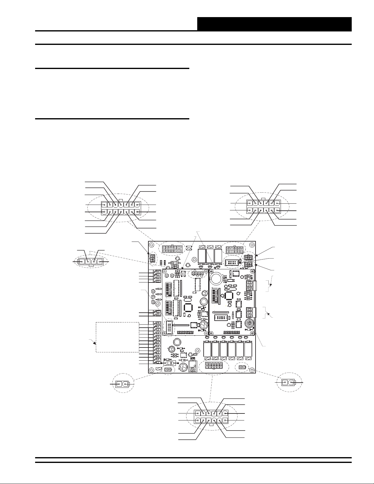
PIN11 - 24 VAC
PIN12 - RAB
PIN13 - CO2
PIN14 - GND
PIN7-24VAC
PIN6 - GND
PIN5 - OAT
PIN4-24VAC
PIN2 - WH PIN3 - RD
PIN1 - BK
HGR VALVE
(SAT) SUPPLY AIR TEMPERATURE SENSOR INPUT
(GND) SUPPLY AIR TEMPERATURE SENSOR INPUT
SEE THERMOSTAT
AND DEHUMIDISTAT
WIRING DIAGRAMS
FOR COMPLETE
WIRING DETAILS
(A1) ECONOMIZER 24 VAC JUMPER
(C1) CLOGGED FILTER SWITCH 24 VAC OUTPUT
(C2) CLOGGED FILTER SWITCH 24 VAC OUTPUT
(A2) ECONOMIZER 24 VAC JUMPER
PIN1-24VAC
ECONO SECTION
P1
HSS CONNECTOR
PIN4 - GN
MHGRV RESET
ECONO POSITION
RETURN AIR BYPASS
GND
PROGRAMMING SOCKET
(R) FROM THERMOSTAT
(C) FROM THERMOSTAT
(RH) FROM DEHUMIDISTAT
(G) FROM THERMOSTAT
(Y1) FROM THERMOSTAT
(Y2) FROM THERMOSTAT
(W1) FROM THERMOSTAT
(W2) FROM THERMOSTAT
(W3) FROM THERMOSTAT
POWER
P10
MHGRV
RESET
ECONO
POS
RAB
GND
LD2LD1
LD3
SAT
GND
R
C
GND
RH
G
Y1
Y2
W1
W2
W3
A1
A2
C1
C2
PIN2 - GND
PIN2 - F-SIGNAL
PIN10 - GND
PIN9 - ECONO POS
PIN8 - CFS
PIN1 - ECONO-24VAC
PIN2 - GND
PIN3 - ECS
HB - MHGR BOARD
ECONOSECTION
P1
P3
ECONO
POS
RAB
EXT
HSS
INT
JO2
JO1
C4
LED2
LED1
R2
R3
C7
SETPOINT
1
TB2
2
C12
U2
4
R27
8
OFF
16
32
R34
64
128
C15
R40
C3
ADD
1
2
4
C19
8
TB1
OFF
16
32
64
C25
128
RESET
C1
LIMIT
PROGRAM
SOCEKT
P1
C27
P5
P5
L1
C30
C29
R66
R67
D23
TB3
V10
R69
POWER
24VAC
GND
C33
P10
PIN3 - GND
PIN1 - GND
PIN7 - COOL-2
PIN8 - COOL-1
PIN9 - LPS
D1
R2
R3
D5
R6
R9
R1
R17
R20
D6
R26
R28
D8
R37
R38
D10
R45
R47
D12
R54
R55
D14
R62
R64
RN3
D15
MOD HGR
C1
R1
C3
R14
R24
R24
HBMHGR
YS101988
RN2
R35
X1
R43
RN1
R52
C26
R59
HB/VBUNIT BOARD
MADEIN THE USA
R68
C6
SERIAL#
C10
REV1
C14
C9 C8
C18
C22
U4
C2
C28
D22
U7
9936
MC34064A
2. All wiring is to be in accordance with local and national
electrical codes and specifi cations.
3. Minimum wire size for 24 VAC thermostat wiring should
be 22 gauge.
4. Minimum wire size for all sensors should be 24 gauge.
5. Be sure that all wiring connections are properly inserted
and tightened into the terminal blocks. Do not allow wire
strands to stick out and touch adjoining terminals which
could potentially cause a short circuit.
6. Be sure all modular wiring harness connectors are seated
fi rmly in their respective modular connectors on the HB
circuit board.
PIN10 - 24 VAC
PIN11 - 24 VAC
PIN12 - GND
PIN6 - HEAT-1
PIN5-24VAC
PIN4 - GND
HB - PROCESSOR BOARD
SW1
V1P9V2
K2
C2
D20
D21
Q9
Q9
Q8
R5
VALVE
HGR
R7
R10
MADEIN THE USA
R12
R16
R15
R19
R18
R21
U5
R22
R23
C9
R25
D7
C12
1
R30
2
R32
4
C4
R36
C35
8
C16
D9
16
L1
32
R41
R42
C34
R44
SW1
D11
R49
D2
R6
C11
R51
RN1
R53
C21
R5
9936
D13
MC34064A
R56
C7
R57
P4
R4
R60
U7
YS101992
REV4
C32
0I
VR2
HBAUXILIARY
R63
PROCESSORBOARD
R65
YS102002
C5
D16
REV2
C10
D1
P2
Q5
Q4
D4
K5
C31
V5
P4
P4
COOLING SECTION
HEAT SECTION
PIN9 - HSM
PIN8 - HEAT-3
PIN7 - HEAT-2
P9
PIN1 - FAN STATUS
PIN2-24VAC
PIN3-24VAC
HEATSECTION
V3
P11
P6
X2
C38
C12
C3
D2Q3D3
P-BUS
P8
HSS
C37
R71
R8
U2
R11
R13
C11
R6
C5
R7
D3
U1
TB1
TMP
ADJ
C17
GND
R39
C39
R8
C20
R9
D4
R3
U6
R2
U5
R58
R61
COMM
C46
R
C2
485DRV
U8
SH
T
R75
R74
C5
R73
HSSDRV
R72
C40
TTL
P3
P2
P7
D1
Q1
D1
PROGRAM
SOCKET
K4
D19
Q7
Q7
C36
C7
SC1
R1
D2
C8
RN1
CLOCK
C8
C9
C10
C14
U2
C13
C11
ADDR
11.059Mhz
C6
R29
C13
SERIAL#
X1
U4
Q10
C43
U1
RN2
EEPROM
C1
X1
C41
C23
C24
C15
U3
C44
C42
U4
C45
R4
C4
R4
U5
LD1
VR1
REC
AUX CPU
Q6
Q2
D18
D17
R31
R33
U3
R70
R46
R48
R50
P-BUS CONNECTOR
PROGRAMMING SOCKET
HSS CONNECTOR
OPTIONAL SPACE
TEMPERATURE SENSOR
TMP
INPUT TERMINALS
ADJ
"ADJ" TERMINAL IS ONLY
GND
USED WITH SENSORS
EQUIPPED WITH THE SLIDE
ADJUST OPTION. CONNECT
"ADJ" TERMINAL ON BOARD TO
"AUX" TERMINAL ON SENSOR
R
SH
T
RS-485 COMM TERMINALS
USED TO CONNECT TO
COMMLINK OR OTHER
CONTROLLERS ON THE
LOCAL COMMUNICATION LOOP
AS REQUIRED
MINI-DIN CONNECTOR
V6V9V7
V8P2V4
SERIAL#
COOLING
SECTION
AUX
PIN1 - E-FAN
P2
PIN2 - GND
AUX
PIN4 - LLT
PIN5 - GND
PIN6 - C-FAN
PIN12 - H-FAN
PIN11 - L-FAN
PIN10 - HPS
Figure 2: HB Controller Wiring (Shown with Optional MHGRV & HB Processor Boards Installed)
HB Controller Technical Guide
7
Page 8
Installation & Wiring
Controller Installation & Wiring
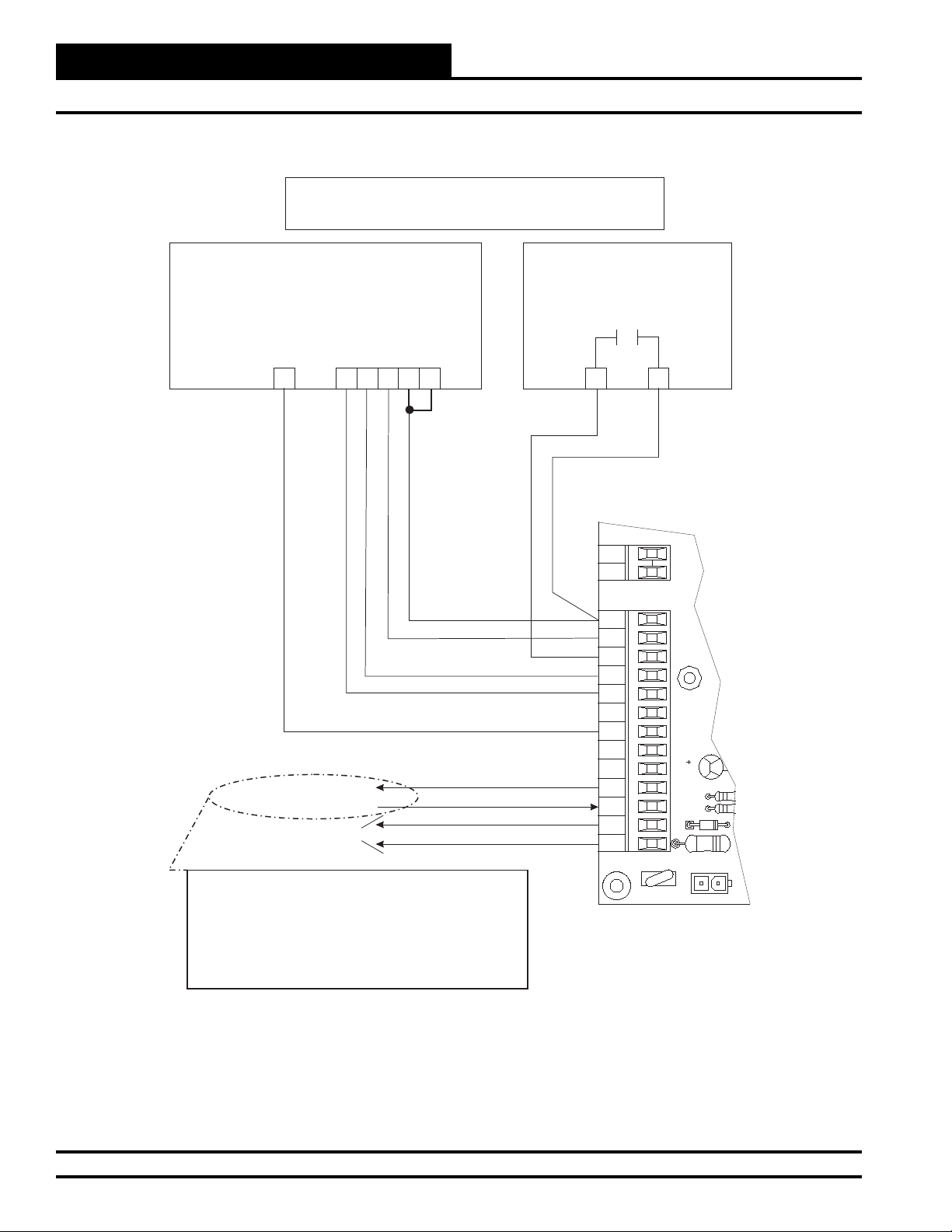
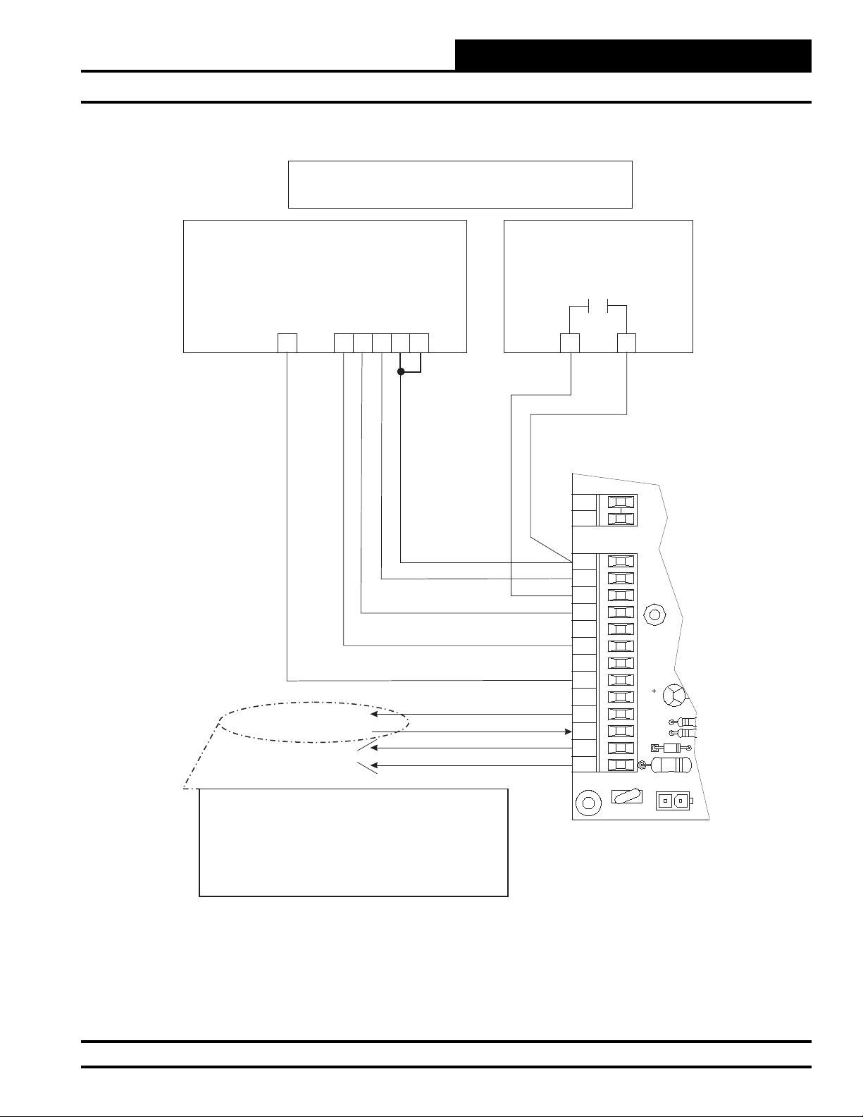
Single Stage T-stat Wiring For HB Unit
Single Stage T-stat Wiring For HB Units
With 1 Stage Cooling&1StageHeating
With 1 Stage Cooling&1StageHeating
Zone
Zone
Single-Stage Thermostat
(24VAC)
1-Cool / 1-Heat
RC
G
Y1
C
W1
RH
24VAC Power Supply
24VAC to Economizer
Clogged Filter Indicator
(Outputs 24VAC)
24VAC
GND
Note:
The economizer will not have 24VAC to the actuator
without installing a jumper wire between A1 and A2.
If a device needs to disable the economizer, install a
normally closed contact between A1 and A2.
If a device needs to enable the economizer, install a
normally open contact between A1 and A2.
Dehumidistat (24VAC)
Normally Open
DH
DH
HB Controller Terminal Block
TB1
SAT
GND
R
(GND)
C
RH
G
Y1
Y2
W1
W2
W3
A1
A2
C1
C2
TB3
R66
R67
V10
C30
POWER
P10
Figure 3: Single-Stage T-Stat Wiring for HB Unit with 1-Stage Cooling & 1-Stage Heating
8
HB Controller Technical Guide
Page 9
Installation & Wiring
Controller Installation & Wiring
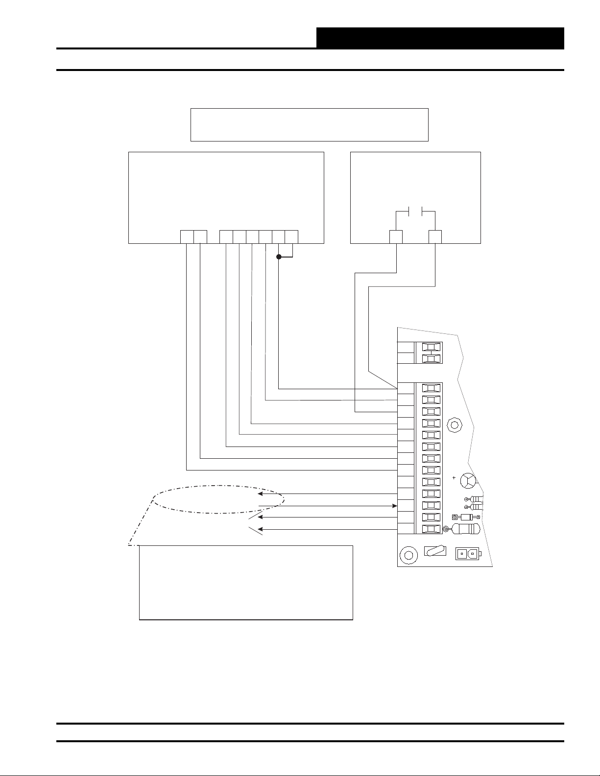
Single Stage T-stat Wiring For HB Units
With 2 Stage Cooling&2StageHeating
Single-Stage Thermostat
(24VAC)
1-Cool / 1-Heat
RC
G
Y1
C
W1
RH
24VAC Power Supply
24VAC to Economizer
Clogged Filter Indicator
(Outputs 24VAC)
24VAC
GND
Note:
The economizer will not have 24VAC to the actuator
without installing a jumper wire between A1 and A2.
If a device needs to disable the economizer, install a
normally closed contact between A1 and A2.
If a device needs to enable the economizer, install a
normally open contact between A1 and A2.
Dehumidistat (24VAC)
Normally Open
DH
DH
HB Controller Terminal Block
TB1
SAT
GND
R
(GND)
C
RH
G
Y1
Y2
W1
W2
W3
A1
A2
C1
C2
TB3
R66
R67
V10
C30
POWER
P10
Figure 4: Single-Stage T-Stat Wiring for HB Units with 2-Stage Cooling & 2-Stage Heating
HB Controller Technical Guide
9
Page 10

Installation & Wiring
Controller Installation & Wiring
Single Stage T-stat Wiring For HB Units
With 2 Stage Cooling&3StageHeating
Zone
Zone
Single-Stage Thermostat
(24VAC)
1-Cool / 1-Heat
RC
G
Y1
C
W1
RH
24VAC Power Supply
24VAC to Economizer
Clogged Filter Indicator
(Outputs 24VAC)
24VAC
GND
Note:
The economizer will not have 24VAC to the actuator
without installing a jumper wire between A1 and A2.
If a device needs to disable the economizer, install a
normally closed contact between A1 and A2.
If a device needs to enable the economizer, install a
normally open contact between A1 and A2.
Dehumidistat (24VAC)
Normally Open
DH
DH
HB Controller Terminal Block
TB1
SAT
GND
R
(GND)
C
RH
G
Y1
Y2
W1
W2
W3
A1
A2
C1
C2
TB3
V10
R66
R67
C30
POWER
P10
Figure 5: Single-Stage T-Stat Wiring for HB Units with 2-Stage Cooling & 3-Stage Heating
10
HB Controller Technical Guide
Page 11
Installation & Wiring
Controller Installation & Wiring
Multi-Stage T-stat Wiring For HB Units
With 2 Stage Cooling&2StageHeating
Multi-Stage Thermostat
(24VAC)
2-Cool / 2-Heat
RC
W2
W1
G
Y1
C
Y2
RH
24VAC Power Supply
24VAC to Economizer
Clogged Filter Indicator
(Outputs 24VAC)
24VAC
GND
Note:
The economizer will not have 24VAC to the actuator
without installing a jumper wire between A1 and A2.
If a device needs to disable the economizer, install a
normally closed contact between A1 and A2.
If a device needs to enable the economizer, install a
normally open contact between A1 and A2.
Dehumidistat (24VAC)
Normally Open
DH
DH
HB Controller Terminal Block
TB1
SAT
GND
R
(GND)
C
RH
G
Y1
Y2
W1
W2
W3
A1
A2
C1
C2
TB3
V10
R66
R67
C30
POWER
P10
Figure 6: Multi-Stage T-Stat Wiring for HB Units with 2-Stage Cooling & 2-Stage Heating
HB Controller Technical Guide
11
Page 12

Installation & Wiring
Controller Installation & Wiring
Multi-Stage T-stat Wiring For HB Units
With 2 Stage Cooling&3StageHeating
Zone
Zone
Multi-Stage Thermostat
(24VAC)
2-Cool / 3-Heat
W3
W2
W1
Y1
Y2
RC
G
C
RH
24VAC Power Supply
24VAC to Economizer
Clogged Filter Indicator
(Outputs 24VAC)
24VAC
GND
Note:
The economizer will not have 24VAC to the actuator
without installing a jumper wire between A1 and A2.
If a device needs to disable the economizer, install a
normally closed contact between A1 and A2.
If a device needs to enable the economizer, install a
normally open contact between A1 and A2.
Dehumidistat (24VAC)
Normally Open
DH
DH
HB Controller Terminal Block
TB1
SAT
GND
R
(GND)
C
RH
G
Y1
Y2
W1
W2
W3
A1
A2
C1
C2
TB3
R66
R67
V10
C30
POWER
P10
Figure 7: Multi-Stage T-Stat Wiring for HB Units with 2-Stage Cooling & 3-Stage Heating
12
HB Controller Technical Guide
Page 13
Installation & Wiring
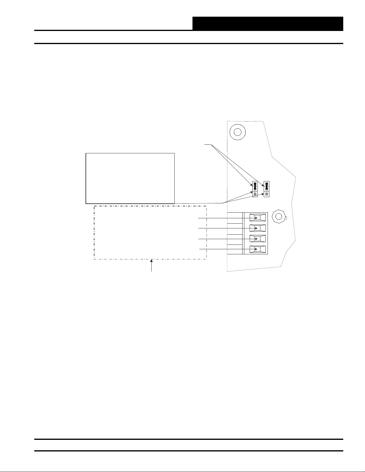
Optional Jumper
Locations
For External Control
Controller Installation & Wiring
Note:
The factory jumpers are located on
the bottom two pins for each 3-pin
header. For field control of either the
Economizer and/or the Return Air
Bypass, move their respective
jumpers to the “External” position on
the jumper pins as shown.
0-10VDC Input Signal for
Modulating Hot-Gas Reheat
2-10VDC Economizer Signal
0-10VDC Return Air Bypass Signal
Common Ground for External Signals
External Control Inputs
MHGRV
RESET
ECONO
POS
RAB
GND
POS
ECONO
JO1
TB2
POS
JO2
RAB
EXTERNAL
INTERNAL
C7
Figure 8: Field Wiring & Jumper Settings for Mod Hot Gas Reheat, Economizer, and Return Air Bypass
HB Controller Technical Guide
13
Page 14
Programming
Programming with the HB Service Tool
Zone
Zone
Entering Passcodes
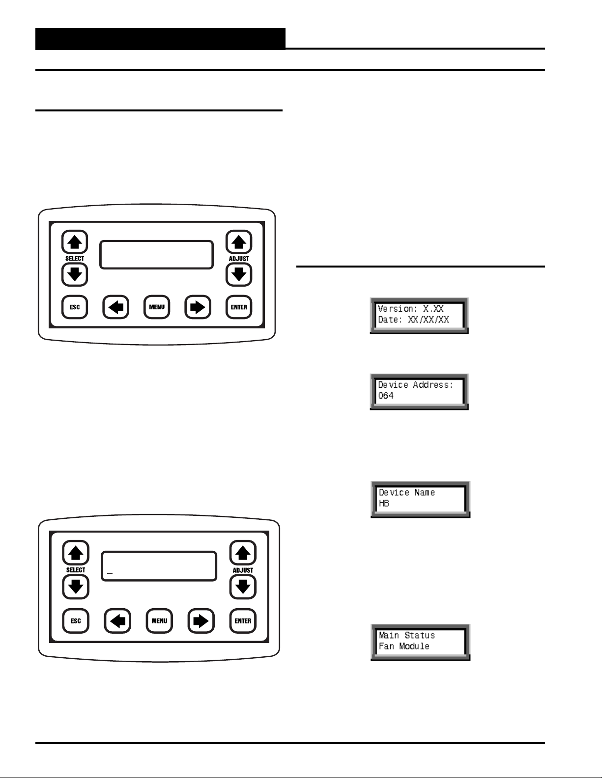
The HB Service Tool is used to program setpoints and view the status
of the HB controller. It is connected to the HB controller by means of
a modular cable. The cable is connected between the HB Service Tool
and the HB controller board. The HB Service Tool doesn’t require batteries or a separate power source, because all power to operate the HB
Service Tool is provided through this cable. The HB controller must be
powered in order for the HB Service Tool to function.
Device Address
064
When the HB Service Tool is initially powered up, the program version
and the current time and date will be displayed. After the initial power
up, this screen only appears when the HB power is removed and then
reapplied. Press ENTER, and the HB Service Tool will check all current
parameters. When it has fi nished this checking procedure, press ENTER,
and the main HB programming screen will be displayed. If you want
to change setpoints, you will need to enter a passcode at this time. If
you only want to view status, a passcode is not required, and you can
proceed to view status directly by pressing the ENTER key.
If you want to change the Passcode, hold down on the UP and DOWN
SELECT ARROWS simultaneously and the following screen will be
displayed.
the DOWN arrow decreases. When the desired letter appears, press the
RIGHT ARROW key to advance to the next letter fi eld. Once all four
letter fi elds spell the desired passcode, press the ENTER key.
Available passcodes are:
● “OPER” = The Operator is at level 1 for Status and
Setpoints
● “CONT” = The Contractor is at level 2 for Status, Setpoints
and Force Modes
Again, if no passcode is entered, the default level is 0 and only allows
viewing of the status screens.
General Procedures
When the HB Service Tool is initially powered up, this screen will be
displayed. Press ENTER to proceed to the next screen.
Enter your passcode as described in the previous section and proceed by
pressing the MENU key. The following screen will be displayed:
Line #2 displays the default address for the HB Controller. If equipped
with a MHGRV Controller, adjust the address to 065 in a similar fashion
as you did when you entered your passcode. Once you have the desired
address on the screen, press the ENTER key. The following screen will
be displayed:
Enter Code
AAAA
The passcode entry screen uses a four-digit alpha passcode. Position
the cursor under the fi rst letter fi eld. To select the desired letter, use the
ADJUST ARROWS. The UP arrow increases through the alphabet and
14
Line #2 displays the controller name or program name. Press the ENTER
key to advance.
Module Selection Screens
After pressing ENTER in the previous step, the fi rst available programming module screen appears. All of the HB controller Status and Setpoint Screens are grouped in specifi c modules designated by a specifi c
function name.
Using the select arrows, scroll to select the desired module on line #1
and press the ENTER key.
HB Controller Technical Guide
Page 15
Programming
Programming with the HB Service Tool
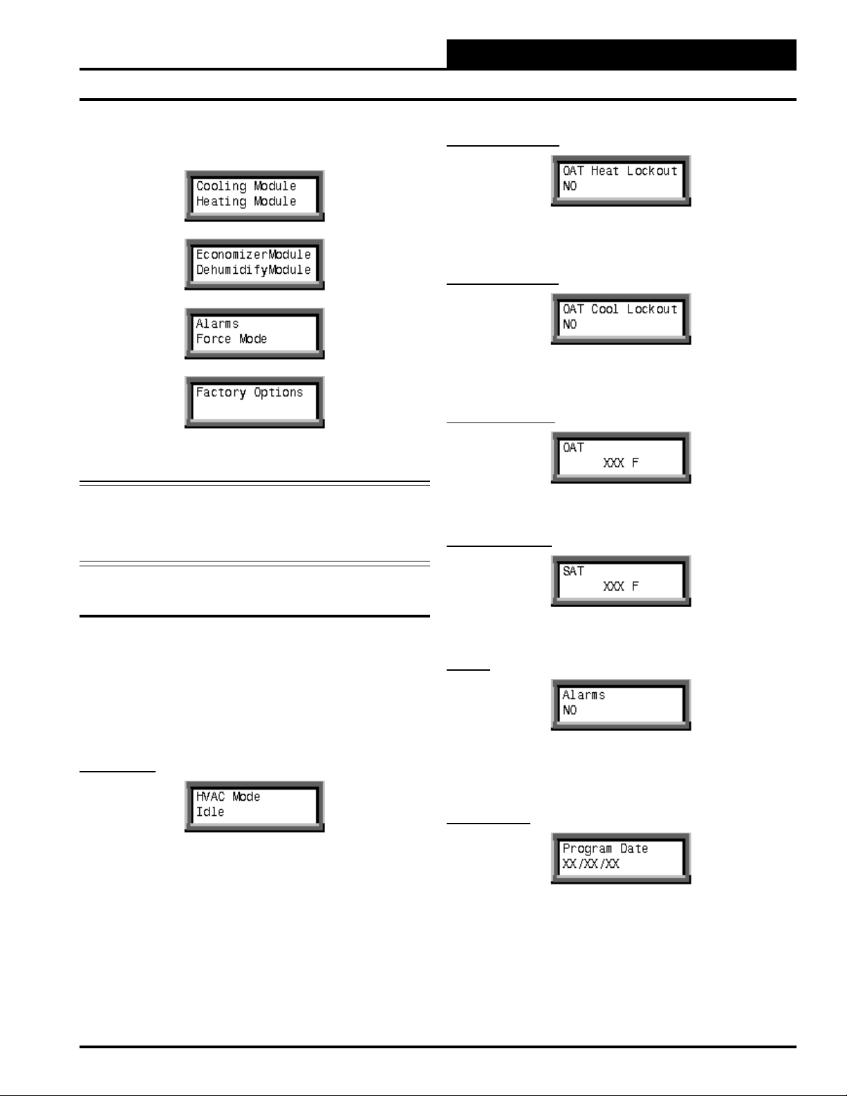
The other available module screens are listed below in the order that
they would appear as you scroll down.
Factory Options should not be accessed without contacting AAON®
or WattMaster.
Warning: The Factory Options settings should only be ap-
plied when authorized by AAON® or WattMaster
Technical Support personnel. Serious damage to the
controller and/or HVAC unit could result from im proper use of the Factory settings.
OAT Heat Lockout
Line #2 displays “YES” if the Outdoor Air Temperature is above the
Heating Lockout Temperature Setpoint.
OAT Cool Lockout
Line #2 displays “YES” if the Outdoor Air Temperature is below the
Cooling Lockout Temperature Setpoint.
OAT Temperature
Line #2 displays the current Outdoor Air Temperature.
SAT Temperature
HB Controller Status & Setpoints
The Status and Setpoint screens for the various modules are accessed by
selecting a specifi c module and pressing the ENTER key.
Main Status Screens
The Main Status Screen is accessed by selecting the Main Status Module
and pressing the ENTER key. This screen, as its name indicates, allows
you to view the Main Status screens for the HB controller. After the
ENTER key is pressed, the following screen will be displayed:
HVAC Mode
Line #2 displays one of the following HVAC Modes:
• Idle • Venting
• Cooling • Econo Cooling
• Heating • Dehumidify
• Econo Dehumidify • Fault
• Force
Press the down SELECT arrow key or up SELECT arrow key to move
forward or backward through the Main Status screens.
Line #2 displays the current Supply Air Temperature.
Alarms
Line #2 displays “YES” if an alarm is active. To identify the active
alarm(s), press the ESC key, select the Alarm Module, and scroll through
the available alarms using the up and down SELECT arrow keys.
Program Date
Line #2 displays the Month/Day/Year that the HB Controller software
was created.
HB Controller Technical Guide
15
Page 16

Programming
Programming with the HB Service Tool
Zone
Zone
Program Time
Line #2 displays the time, in 24-hour (military) format, that the HB
Controller software was created.
Program Version
Line #2 displays the HB Controller software version number.
Reset Counts
Line #2 displays the total number of times the HB Controller has been
reset or has had its power cycled.
Fan Status
Line #2 displays the current Supply Fan Status. If the Supply Fan is on,
line #2 displays either “Fan Low Speed” or “Fan High Speed.” Line #2
displays “ON” if the High Speed Fan Relay is active.
Supply Fan Analog Output Signal
Line #2 displays the current Supply Fan Analog Output Signal in DC
Volts.
Fan Module Setpoint Screens
The Fan Module Setpoint Screens are accessed by navigating to the
Fan Module and then pressing the ENTER key. The following screen
will then appear:
Fan Module Status Screens
The Fan Module Status Screens are accessed by navigating to the Fan
Module and pressing the ENTER key. The following screen will then
appear:
Select “Status” by pressing the ENTER key. Press the up and down
SELECT arrow keys to move forward and backward through the Fan
Module Status screens.
Fan Terminal Active
Line #2 displays “YES” if there is a 24 VAC signal connected to the
“G” Fan terminal on the HB controller.
Press the down SELECT arrow key until “Setpoints” is on the top line
of the screen and then press the ENTER key. Press the up and down
SELECT arrow keys to move forward and backward through the Fan
Setpoint screens.
Please see the Appendix section in the back of this manual for Tables
listing the minimum, maximum, and default setpoints for all of the
setpoint screens.
Supply Fan Confi guration
Select the appropriate Supply Fan Confi guration by using the up and
down ADJUST arrow keys and then pressing the ENTER key. Available
options are Two-Speed or Adj. Two-Speed.
16
HB Controller Technical Guide
Page 17

Programming
Programming with the HB Service Tool
Adjustable Two-Speed Supply Fan Low-Speed Signal
Description Min. Default Max.
Low Speed Fan Signal 1.0 VDC 3.0 VDC 10.0 VDC
Adjust the desired Low-Speed Output Signal for Adjustable Two-Speed
Fan confi gurations by pressing the up or down ADJUST arrow key until
the desired value is displayed and then pressing the ENTER key. Settings are in DC Volts.
Adjustable Two-Speed Supply Fan High Speed Signal
Description Min. Default Max.
High Speed Fan Signal 1.0 VDC 10.0 VDC 10.0 VDC
Adjust the desired High-Speed Output Signal for Adjustable Two-Speed
Fan confi gurations by pressing the up or down ADJUST arrow key until
the desired value is displayed and then pressing the ENTER key. Settings are in DC Volts.
Fan Status
Line #2 displays the current Supply Fan Status. If the Supply Fan is on,
line #2 displays either “Fan Low Speed” or “Fan High Speed.”
Fan Signal
Line #2 displays the current Supply Fan Analog Output Signal in DC
Volts.
Cooling Relay #1
Line #2 displays “ON” if Cooling Relay #1 is active.
Cooling Relay #2
Cooling Module Status Screens
The Cooling Module Status Screens are accessed by navigating to the
Cooling Module screen ad pressing the ENTER key. The following
screen will then appear:
Select “Status” by pressing the ENTER key. Press the up and down
SELECT arrow keys to move forward and backward through the Cooling Module Status screens.
Cooling Stage 1 Energized
Line #2 displays “YES” if there is a 24 VAC signal on HB Controller
terminal “Y1.”
Cooling Stage 2 Energized
Line #2 displays “ON” if Cooling Relay #2 is active.
Liquid Line Temperature
Line #2 displays the current Liquid Line Temperature.
Condenser Fan Relay
Line #2 displays “ON” if the Condenser Fan Relay is active.
Low Pressure Switch
Line #2 displays “YES” if there is a 24 VAC signal on HB Controller
terminal “Y2.”
HB Controller Technical Guide
Line #2 displays the current status of the Low Pressure Switch. It will
only display “CLOSED” when Cooling Relay #1 is active and the Low
Pressure Switch is operating correctly.
17
Page 18

Programming
Programming with the HB Service Tool
Zone
Zone
High Pressure Switch
Line #2 displays the current status of the High Pressure Switch. It will
only display “CLOSED” when Cooling Relay #1 relay is active and the
High Pressure Switch is operating correctly.
Cooling Module Setpoint Screens
The Cooling Module Setpoint Screens are accessed by navigating to
the Cooling Module screen and then pressing the ENTER key. The
following screen will then appear:
Press the down SELECT arrow key until “Setpoints” is on the top line
of the screen and then press the ENTER key. Press the up and down
SELECT arrow keys to move forward and backward through the Cooling Module Setpoint screens.
Cooling Stages Quantity
Low Supply Air Temperature Cutoff
Description Min. Default Max.
Supply Air Low Temperature
Limit Cut Off
Adjust the Low Supply Air Temperature Cutoff and then press the
ENTER key. The value must be below the Economizer Oat Enable.
32ºF 40ºF 80ºF
Cooling Minimum Off Time
Description Min. Default Max.
Minimum Off Time 180 Sec 180 Sec 900 Sec
Adjust the desired Cooling Minimum Off Time and then press the
ENTER key.
Cooling Minimum On Time
Description Min. Default Max.
Cooling Stages 1 2 2
Adjust the quantity of Cooling Stages or Steps of Cooling and then
press the ENTER key.
Condenser Fan Control
Select “YES” for Condenser Fan Control if you are using a Liquid Line
Temperature Sensor and then press the ENTER key.
Outdoor Air Temperature Cooling Lockout
Description Min. Default Max.
Cooling Lockout Temperature 32ºF 40ºF 80ºF
Adjust the Outdoor Air Temperature Cooling Lockout and then press
the ENTER key.
Adjust the desired Cooling Minimum On Time and then press the
ENTER key.
Description Min. Default Max.
Minimum On Time 300 Sec 300 Sec 900 Sec
Cooling Stage-Up Delay
Description Min. Default Max.
Staging Up Delay Interval 180 Sec 180 Sec 900 Sec
Adjust the desired Cooling Stage-Up Delay time and then press the
ENTER key.
Cooling Stage Down Delay
Description Min. Default Max.
Staging Down Delay Interval 60 Sec 60 Sec 900 Sec
Adjust the desired Cooling Stage-Down Delay time and then press the
ENTER key.
18
HB Controller Technical Guide
Page 19

Programming
Programming with the HB Service Tool
Low Pressure Switch Delay
Description Min. Default Max.
Low Pressure Delay Period 5 Sec 30 Sec 60 Sec
The Low Pressure Switch Delay time is a factory setting and should
not be changed unless authorized to do so by WattMaster or AAON
Technical Support.
Low Pressure Switch Safety Delay
Description Min. Default Max.
Low Pressure Safety 5 Sec 5 Sec 30 Sec
The Low Pressure Switch Safety Delay time is a factory setting and
should not be changed unless authorized to do so by WattMaster or
AAON® Technical Support.
LPS Maximum Trips
Condenser Fan Deactivation Temperature
The Condenser Fan Deactivation Temperature is a factory setting and
should not be changed unless authorized to do so by WattMaster or
AAON® Technical Support.
®
Auto Stage-Up Time
Description Min. Default Max.
Auto Staging Up Delay 180 Sec 600 Sec 900 Sec
The Auto Stage-Up Time can be adjusted on this screen when you are
using a single-stage thermostat with a multi-stage HB unit.
Heating Module Status Screens
The Heating Module Status Screens are accessed by navigating to the
Heating Module screen and pressing the ENTER key. The following
screen will then appear:
Description Min. Default Max.
Low Pressure Max. Trip Point 1 3 5
The Low Pressure Switch Max Trips is a factory setting and should
not be changed unless authorized to do so by WattMaster or AAON®
Technical Support.
Cooling Fan Off Delay
Description Min. Default Max.
Fan Off Delay Period 1 Sec 45 Sec 120 Sec
The Cooling Fan Off Delay is a factory setting and should not be
changed unless authorized to do so by WattMaster or AAON® Technical Support.
Condenser Fan Activation Temperature
Select “Status” by pressing the ENTER key. Press the up and down
SELECT arrow keys to move forward and backward through the Heating Module Status screens.
Heating Stage 1 Energized
Line #2 displays “YES” if there is a 24 VAC signal on HB Controller
terminal “W1.”
Heating Stage 2 Energized
Line #2 displays “YES” if there is a 24 VAC signal on HB Controller
terminal “W2.”
The Condenser Fan Activation Temperature is a factory setting and
should not be changed unless authorized to do so by WattMaster or
AAON® Technical Support.
HB Controller Technical Guide
19
Page 20

Programming
Programming with the HB Service Tool
Zone
Zone
Heating Stage 3 Energized
Line #2 displays “YES” if there is a 24 VAC signal on HB Controller
terminal “W3.”
Fan Status
Line 2 displays the current Supply Fan Status. If the Supply Fan is on,
line #2 displays either “Fan Low Speed” or “Fan High Speed.”
Fan Signal
Line #2 displays the current Supply Fan Analog Output Signal in DC
Volts.
Heating Module Setpoint Screens
The Heating Module Setpoint Screens are accessed by navigating to
the Heating Module and then pressing the ENTER key. The following
screen will then appear:
Press the down SELECT arrow key until “Setpoints” is on the top line
of the screen and then press the ENTER key. Press the up and down
SELECT arrow keys to move forward and backward through the Heating Module Setpoint screens.
Heating Stages Quantity
Description Min. Default Max.
Heating Stages 1 3 3
Adjust the quantity of Heating Stages and then press the ENTER key.
Outdoor Air Temperature Heating Lockout
Heating Relay #1
Line #2 displays “ON” if Heating Relay #1 is active.
Heating Relay #2
Line #2 displays “ON” if Heating Relay #2 is active.
Heating Relay #3
Line #2 displays “ON” if Heating Relay #3 is active.
Heat Safety Monitor
Line #2 displays “OPEN” anytime the Heat Safety Monitor is open.
Description Min. Default Max.
Heating Lockout Temperature 40ºF 80ºF 120ºF
Adjust the Outdoor Air Temperature Heating Lockout and then press
the ENTER key.
Low Supply Air Temperature Cutoff
Description Min. Default Max.
Supply Air Low Temperature
Limit Cut Off
Adjust the Low Supply Air Temperature Cutoff and then press the
ENTER key.
32ºF 40ºF 80ºF
High Supply Air Temperature Cutoff
Description Min. Default Max.
Supply Air High Temperature
Limit Cut Off
Adjust the High Supply Air Temperature Cutoff and then press the
ENTER key.
120ºF 150ºF 170ºF
20
HB Controller Technical Guide
Page 21

Programming
Programming with the HB Service Tool
Heating Minimum Off Time
Description Min. Default Max.
Minimum Off Time 60 Sec 60 Sec 900 Sec
Adjust the desired Heating Minimum Off Time and then press the
ENTER key.
Heating Minimum On Time
Description Min. Default Max.
Minimum On Time 120 Sec 120 Sec 900 Sec
Adjust the desired Heating Minimum On Time and then press the
ENTER key.
Heating Stage-Up Delay
Description Min. Default Max.
Staging Up Delay Interval 180 Sec 180 Sec 900 Sec
Heating Fan Off Delay
Description Min. Default Max.
Fan Off Delay Period 1 Sec 120 Sec 180 Sec
The Heating Fan Off Delay is a factory setting and should not be
changed unless authorized to do so by WattMaster or AAON® Technical Support.
Auto Stage-Up Time
Description Min. Default Max.
Auto Staging Up Delay 180 Sec 600 Sec 900 Sec
The Auto Stage-Up Time can be adjusted on this screen when you are
using a single-stage thermostat with a multi-stage HB unit.
Economizer Module Status Screens
The Economizer Module Status Screens are accessed by navigating to
the Economizer Module and pressing the ENTER key. The following
screen will then appear:
Adjust the desired Heating Stage-Up Delay time and then press the
ENTER key.
Heating Stage Down Delay
Description Min. Default Max.
Staging Down Delay Interval 60 Sec 60 Sec 900 Sec
Adjust the desired Heating Stage Down Delay time and then press the
ENTER key.
Heat Safety Monitor Maximum Trips
Description Min. Default Max.
Heat Safety Maximum Count 1 3 5
The Heating Safety Maximum Trips is a factory setting and should
not be changed unless authorized to do so by WattMaster or AAON
Technical Support.
Select “Status” by pressing the ENTER key. Press the up and down
SELECT arrow keys to move forward and backward through the
Economizer Module Status screens.
Economizer Current Position
Line #2 displays the current Economizer Position as a percent open
value.
Supply Air Temperature
Line #2 displays the current Supply Air Temperature.
®
HB Controller Technical Guide
21
Page 22

Programming
Programming with the HB Service Tool
Zone
Zone
Outdoor Air Temperature
Line #2 displays the current Outdoor Air Temperature.
Fan Status
Line #2 displays the current Supply Fan status. If the Supply Fan is on,
line #2 displays either “Fan Low Speed” or “Fan High Speed.”
Fan Signal
Line #2 displays the current Supply Fan Analog Output Signal in DC
Volts.
Exhaust Fan Relay
Economizer Module Setpoint Screens
The Economizer Module Setpoint Screens are accessed by navigating
to the Economizer Module and then pressing the ENTER key. The following screen will then appear:
Press the down SELECT arrow key until “Setpoints” is on the top line
of the screen and then press the ENTER key. Press the up and down
SELECT arrow keys to move forward and backward through the Economizer Module Setpoint screens.
Economizer Confi guration
Description Min. Default Max.
Outdoor Air Enable Temp 33ºF 55ºF 65ºF
Select either “Has Economizer” or “No Economizer” and then press the
ENTER key. The value must be greater than the OAT Lockout.
.
Outdoor Air Temperature Enable
Line #2 displays “ON” when the Exhaust Fan Relay is active.
Carbon Dioxide Level
Line #2 displays the Current Carbon Dioxide levels, given in parts per
million.
Economizer Change Over Switch
Line #2 displays “CLOSED” if there is a 24 VAC signal on the Economizer Changeover Switch input. This signal is provided by an Enthalpy
controller to enable the economizer for free Cooling.
Description Min. Default Max.
Outdoor Air Enable Temp 33ºF 55ºF 65ºF
Adjust the Outdoor Air Temperature to enable Economizer Free Cooling
and then press the ENTER key.
OAT Changeover to Mechanical Cooling
Description Min. Default Max.
ECS OAT Enable Temp 55ºF 65ºF 75ºF
Adjust the Outdoor Air Temperature that will allow supplemental Mechanical Cooling during ECS Economizer operation and then press the
ENTER key.
CO2 Minimum Position with Low-Speed Fan
Description Min. Default Max.
Min. with Low-Speed Fan 0% 10% 100%
Adjust the Economizer Minimum Position during Low-Speed Supply
Fan operation when CO
and then press the ENTER key.
levels are below the Minimum CO2 setpoint
2
22
HB Controller Technical Guide
Page 23

Programming
Programming with the HB Service Tool
CO2 Minimum Position with High-Speed Fan
Description Min. Default Max.
Min. with High-Speed Fan 0% 5% 100%
Adjust the Economizer Minimum Position during High-Speed Supply
Fan operation when CO2 levels are below the Minimum CO2 setpoint
and then press the ENTER key.
CO2 Maximum Position with Low Speed Fan
Description Min. Default Max.
Max. with Low-Speed Fan 0% 50% 100%
Adjust the Economizer Maximum Position during Low-Speed Supply
Fan operation when CO2 levels are above the Maximum CO2 setpoint
and then press the ENTER key.
CO Maximum Position with High-Speed Fan
Description Min. Default Max.
Max. with High Speed Fan 0% 30% 100%
Adjust the Economizer Maximum Position during High-Speed Supply
Fan operation when CO2 levels are above the Maximum CO2 setpoint
and then press the ENTER key.
CO2 Level Economizer Opens Above Minimum
Description Min. Default Max.
Min. CO
2
Adjust the Minimum CO2 Level that will allow the Economizer to
Modulate above its minimum position and then press the ENTER key.
0 PPM 900 PPM 2000 PPM
CO2 Level Economizer Opens to Economizer Maximum
Description Min. Default Max.
Max. CO
Adjust the Maximum CO2 Level that will allow the Economizer to Modulate open to its maximum position and then press the ENTER key.
2
0 PPM 1100 PPM 2000 PPM
Dehumidify Module Status Screens
The Dehumidify Module Status Screens are accessed by navigating to
the Dehumidify Module and pressing the ENTER key. Setpoints are
not available for the Dehumidify Module. After pressing ENTER, the
following screen will appear:
RH Terminal Active
Exhaust Fan On with Low-Speed Fan
Description Min. Default Max.
Low-Speed Supply Fan 0% 50% 100%
Adjust the Economizer Position during Low-Speed Supply Fan operation
that will activate the Exhaust Fan and then press the ENTER key.
Exhaust Fan On with High-Speed Fan
Description Min. Default Max.
High-Speed Supply Fan 0% 30% 100%
Adjust the Economizer Position during High-Speed Supply Fan operation
that will activate the Exhaust Fan and then press the ENTER key.
HB Controller Technical Guide
Line #2 displays “YES” if there is a 24 VAC signal on the “RH”
terminal.
Fan Status
Line #2 displays the current Supply Fan Status. If the Supply Fan is on,
Line #2 displays either “Fan Low Speed” or “Fan High Speed.”
Fan Signal
Line #2 displays the current Supply Fan Analog Output Signal in DC
Volts.
23
Page 24

Programming
Programming with the HB Service Tool
Zone
Zone
RAB Position
Line #2 displays the current Return Air Bypass damper position.
Cooling Relay #1
Line #2 displays “ON” if Cooling Relay #1 is active.
Cooling Relay #2
Line #2 displays “ON” if Cooling Relay #2 is active.
OAT Temperature
Condenser Fan Relay
Line #2 displays “ON” if the Condenser Fan Relay is active.
Alarm Module Status Screens
The Alarm Module Status Screens are accessed by navigating to the
Alarm Module and pressing the ENTER key. Setpoints are not available
for the Alarm Module. After pressing ENTER, the following screen
will appear:
HSM Lockout
Line #2 displays “YES” when the Heat Safety Monitor has tripped more
than the HSM Max Trips setpoint.
HPS Fault
Line #2 displays the current Outdoor Air Temperature.
Economizer Current Position
Line #2 displays the current Economizer Position as a percent
open value.
Supply Air Temperature
Line #2 displays the current Supply Air Temperature.
Liquid Line Temperature
Line #2 displays the current Liquid Line Temperature.
Line #2 displays “YES” when the High Pressure Switch is open and a
Cooling Relay is active.
LPS Lockout
Line #2 displays “YES” when the Low Pressure Switch has tripped
more than the LPS Max Trips setpoint.
B a d O A T S e n s o r
Line #2 displays “YES” when the Outdoor Air Temperature Sensor is
bad or missing.
B a d S A T S e n s o r
Line #2 displays “YES” when the Supply Air Temperature Sensor is
bad or missing.
24
HB Controller Technical Guide
Page 25

Programming
Programming with the HB Service Tool
Bad LLT
Line #2 displays “YES” when Condenser Fan Control is confi gured and
the Liquid Line Temperature Sensor is bad or missing.
High SAT Cutoff
Line #2 displays “YES” when the HB Controller is locked out in High
Supply Air Temperature Cutoff.
Low SAT Cutoff
Line #2 displays “YES” when the HB Controller is locked out in Low
Supply Air Temperature Cutoff.
OAT Cooling Lockout
Force Mode Module Screens
The Force Mode Module screens are accessed by navigating to the
Force Mode Module screen and pressing the ENTER key. After pressing
ENTER, the following screen will appear:
Press the down SELECT arrow key until “Force” is on the top line
of the screen and then press the ENTER key. Press the up and down
SELECT arrow keys to move forward and backward through the Force
Mode Module screens.
Force Time Limit
Description Min. Default Max.
Force Mode Timer 1 Min 60 Min 240 Min
Adjust the desired time needed for forcing the HB Controller into the
Force Module Mode and then press the ENTER key.
Force Mode
Line #2 displays “YES” if the Outdoor Air Temperature is below the
Cooling Lockout Temperature setpoint.
OAT Heating Lockout
Line #2 displays “YES” if the Outdoor Air Temperature is above the
Heating Lockout Temperature setpoint.
Clogged Filter
Line #2 displays “YES” if there is a 24 VAC signal on the Clogged
Filter Input.
Adjust to select “Start” and then press the ENTER key to enter Force
Mode. Adjust to select “Stop” and then press the ENTER key to end
Force Mode.
Fan Speed Force
Adjust to select “Low Speed” and then press the ENTER key to place
the Supply Fan in Low-Speed operation. Adjust to select “High Speed”
and then press the ENTER key to place the Supply Fan in High-Speed
operation.
Fan Signal Force
Adjust the Fan Signal Voltage signal up or down to speed up or slow
down the Supply Fan and then press the ENTER key.
HB Controller Technical Guide
25
Page 26

Programming
Programming with the HB Service Tool
Zone
Zone
Economizer Force
Adjust the Economizer percentage up or down to position the Economizer where needed and then press the ENTER key.
Return Air Bypass Force
Adjust the Return Air Bypass Damper percentage up or down to position
the Return Air Bypass where needed and then press the ENTER key.
Exhaust Fan Relay Force
Select “YES” to activate the Exhaust Fan Relay and then press the
ENTER key.
Condenser Fan Relay Force
Select “YES” to activate the Condenser Fan Relay and then press the
ENTER key.
Cooling Relay #1 Force
Heating Relay #2 Force
Select “YES” to activate Heating Relay #2 and then press ENTER.
Heating Relay #3 Force
Select “YES” to activate Heating Relay #3 and then press ENTER.
Force Mode Module Setpoint Screens
The Force Mode Module Setpoint screens are accessed by navigating to
the Force Mode Module screen. Press the down SELECT arrow key until
“Setpoints” is on the top line of the screen and then press the ENTER
key. After pressing ENTER, the following screen will appear:
Low-Speed Fan Signal
Description Min. Default Max.
Low-Speed Fan Signal 1.0 VDC 3.0 VDC 10.0 VDC
Adjust the Low-Speed Supply Fan Signal and then press ENTER.
High-Speed Fan Signal
Select “YES” to activate Cooling Relay #1 and then press ENTER.
Cooling Relay #2 Force
Select “YES” to activate Cooling Relay #2 and then press ENTER.
Heating Relay #1 Force
Select “YES” to activate Heating Relay #1 and then press ENTER.
26
Description Min. Default Max.
High-Speed Fan Signal 1.0 VDC 10.0 VDC 10.0 VDC
Adjust the High-Speed Supply Fan Signal and then press ENTER.
CO2 Minimum Position with Low-Speed Fan
Description Min. Default Max.
Min. with Low-Speed Fan 0% 10% 100%
Adjust the economizer minimum position during Low-Speed Supply
Fan operation when CO2 levels are below the Minimum CO2 setpoint
and then press the ENTER key.
HB Controller Technical Guide
Page 27

Programming
Programming with the HB Service Tool
CO2 Minimum Position with High-Speed Fan
Description Min. Default Max.
Min. with High-Speed Fan 0% 5% 100%
Adjust the economizer minimum position during High-Speed Supply
Fan operation when CO2 levels are below the minimum CO2 setpoint
and then press the ENTER key.
CO2 Maximum Position with Low-Speed Fan
Description Min. Default Max.
Max. with Low-Speed Fan 0% 50% 100%
Adjust the Economizer Maximum Position during Low-Speed Supply
Fan operation when CO2 levels are above the Maximum CO2 setpoint
and then press the ENTER key.
CO2 Maximum Position with High-Speed Fan
Factory Options Module Screens
Factory Options should not be accessed without contacting AAON® or
WattMaster.
Warning: The Factory Options settings should only be
applied when authorized by AAON® or WattMaster
Technical Support personnel. Serious damage to the
controller and/or HVAC unit could result from
improper use of these settings.
The Factory Options Module screens are accessed by navigating to the
Factory Option screen and then pressing the ENTER key. After pressing
ENTER, the following screen will then appear:
Force Time Limit
Description Min. Default Max.
Force Mode Timer 1 Min 60 Min 240 Min
Adjust the desired time needed for forcing the HB Controller into the
Force Mode and then press the ENTER key.
Description Min. Default Max.
Max. with High-Speed Fan 0% 30% 100%
Adjust the Economizer Maximum Position during High-Speed Supply
Fan operation when CO2 levels are above the Maximum CO2 setpoint
and then press the ENTER key.
Exhaust Fan On with Low-Speed Fan
Description Min. Default Max.
Low-Speed Supply Fan 0% 50% 100%
Adjust the Economizer position during Low-Speed Supply Fan operation
that will activate the Exhaust Fan and then press the ENTER key.
Exhaust Fan On with High-Speed Fan
Description Min. Default Max.
High-Speed Supply Fan 0% 30% 100%
Adjust the Economizer position during High-Speed Supply Fan operation
that will activate the Exhaust Fan and then press the ENTER key.
Force No Limit
Adjust this setting to “Yes” to override all factory limits to timers, etc.
and then press the ENTER key. This function requires high-level passcode access. This passcode can only be obtained by calling AAON or
WattMaster Technical Support.
Force Defaults
Adjust this setting to “Yes” to restore all factory limits to timers, etc.
and then press the ENTER key. This function requires high-level passcode access. This passcode can only be obtained by calling AAON or
WattMaster Technical Support.
HB Controller Technical Guide
27
Page 28

Programming
Programming with the HB Service Tool
Zone
Zone
HB Processor Board
HB Processor Board Status Screens
If your HB Controller is equipped with the HB Processor board, you can
access the available Status and Setpoint screens by using the programming directions that follow.
The Device Address Screen is accessed by pressing the MENU key from
any screen. The current Device Address Screen will be displayed. If the
Current device address is set for 064 (HB Controller Address), you must
change the device address to 066 to access the HB Processor screens.
Press the ADJUST ARROW from Device Address 064 to change to
Device Address 66.
Once the correct Device Address of 066 is displayed as shown above,
press ENTER.
Line #2 displays the HB Processor name. Press the ENTER key to
advance to the HB Processor main status screens. The following screen
will then appear:
HVAC Mode
Line #2 displays the current HVAC Mode when Space Temperature
Control is confi gured. Options that may be displayed are Idle, Venting, Heating, or Cooling. Press the ENTER key to continue to the next
screen.
Space Temperature
Line #2 displays the current Space Temperature. Press the ENTER key
to continue to the next screen.
Cooling Setpoint
Line #2 displays the current Cooling Setpoint. Press the ENTER key to
continue to the next screen.
Select “Main Status” by pressing the ENTER key. Press the up and
down SELECT arrow keys to move forward and backward through the
Main Status screens.
Date and Time
Line #1 displays the current date inside the HB Processor. Line #2
displays the current time of day inside the HB Processor in 24-hour
format. Press the ENTER key to continue to the next screen.
Schedule Mode
Line #2 displays the current Schedule Mode. Options that may be displayed are Occupied, Unoccupied, Force Occupied, Force Unoccupied,
Global Occupied, Global Unoccupied, or Override Occupy. Press the
ENTER key to continue to the next screen.
Heating Setpoint
Line #2 displays the current Heating Setpoint. Press the ENTER key to
continue to the next screen.
H/C Demand
Line #2 displays the demand for Heating or Cooling based on the Space
Temperature in reference to the Heating or Cooling setpoint. Press the
ENTER key to continue to the next screen.
Override Left
Line #2 displays the Override Time remaining once the Push-Button
Override on the Space Temperature Sensor has been activated. Press
the ENTER key to continue to the next screen.
28
HB Controller Technical Guide
Page 29

Programming
Programming with the HB Service Tool
Slide Adjust
Line #2 displays the current Slide Adjust value based on the slide position on the Space Temperature Sensor. Press the ENTER key to continue
to the next screen.
Bad Room Temp
Line #2 displays “YES” if Space Temperature control has been confi gured
and the Space Temperature Sensor has failed. Press the ENTER key to
continue to he next screen.
Program Date
Line #2 displays the Date the current Software in the controller was
created. Press the ENTER key to continue to the next screen.
HB Processor Setpoint Screens
The HB Processor Setpoints Screens are accessed by navigating to the
Setpoints Module screen and then pressing the ENTER key. The following screen will appear:
Press the down SELECT arrow key until “Setpoints” is on the top line
of the screen and then press the ENTER key. Press the up and down
SELECT arrow keys to move forward and backward through the HB
Processor Setpoint screens.
Please see the Appendix section in the back of this manual for Tables
listing the minimum, maximum, and default setpoints for all of the
setpoint screens.
FRC Schedule
Using the Adjust keys, toggle for FRC Occupied, FRC Unoccupied, or
No FRC, and press the ENTER key. If you need 24-hour continuous
operation, toggle to FRC Occupied and then press the ENTER key.
Program Time
Line #2 displays the Time of Day the current Software in the controller
was created. Press the ENTER key to continue to the next screen.
Program Version
Line #2 displays the Version of Software in the controller. Press the
ENTER key to continue to the next screen.
Reset Count
Line #2 displays the number of times the controller has had its power
cycled or has restarted. Press the ENTER key to continue to the next
screen.
Space Sensor Control
Using the Adjust keys, toggle for “YES” if a Space Temperature Sensor
will be used to activate the HVAC Modes of Operation and then press
the ENTER key.
Cooling Setpoint
Using the Adjust keys, adjust up or down for the desired Space Cooling
Setpoint and then press the ENTER key.
Heating Setpoint
Using the Adjust keys, adjust up or down for the desired Space Heating
Setpoint and then press the ENTER key.
HB Controller Technical Guide
29
Page 30

Programming
Programming with the HB Service Tool
Zone
Zone
Cooling Setback
Using the Adjust keys, adjust up or down for the desired Night Setback
for Cooling and then press the ENTER key.
Heating Setback
Using the Adjust keys, adjust up or down for the desired Night Setback
for Heating and then press the ENTER key.
HVAC Mode Deadband
Using the Adjust keys, adjust up or down for the desired HVAC Mode
activation point above the Cooling Setpoint and below the Heating
Setpoint and then press the ENTER key.
Global Schedule Index
Using the Adjust keys, adjust up or down for the proper Global Schedule
Index and then press the ENTER key. Use the index number of 18 when
using the one of the Global Scheduling Devices. When using the VCM
or VAV/CAV Controller, use the number 66.
Global Schedule Number
Using the Adjust keys, adjust up or down for the desired Global Schedule
Number and then press the ENTER key. Use 0 if you want to use the
HB Processor’s Internal Schedule, and enter 1 through 5 if you want
to use one of the schedules on an external Global Scheduling Device.
Use the number 1 if you want to use the VCM or VAV/CAV Controller
schedule.
Space Sensor Calibration
Fan Cycle Confi g
Using the Adjust keys, toggle for “YES” if the Supply Fan should only
run during a call or Heating or Cooling and then press the ENTER
key.
Override Time
Using the Adjust keys, adjust up or down for the desired Override Duration when using the push-button on the Space Temperature Sensor and
then press the ENTER key.
Slide Adjust
Using the Adjust keys, adjust up or down for the desired Heating and
Cooling Setpoints Adjustment when using the slide adjustment on the
Space Temperature Sensor and then press the ENTER key.
Using the Adjust keys, adjust up or down for the desired Space Temperature Sensor Calibration Offset and press the ENTER key.
HB Processor Week Schedule Module Screens
Access the HB Processor Week Schedule Module Screens by navigating
to the Week Schedule Module screen and then pressing the ENTER key.
The following screen will appear:
Day of Week
Using the Select keys, toggle for the desired day to enter the occupied
schedule and then press the ENTER key.
Start Time
Press the left arrow key once for the hours and the right arrow key once
for the minutes. Using the Adjust keys, adjust up or down to enter the
correct Start Time for Event #1 and then press the ENTER key.
30
HB Controller Technical Guide
Page 31

Programming
Programming with the HB Service Tool
Note: Time must always be entered in 24-Hour format. The
example shows how an 8:00 A.M. (08:00 Hrs) start time
for Event One on Monday would be set.
Stop Time
Press the left arrow key once for the hours and the right arrow key once
for the minutes. Using the Adjust keys, adjust up or down to enter the
correct Stop Time for Event #1 and then press the ENTER key.
Note: Start Time #1 and Stop Time #1 are used only when you
have one Start/Stop event per day. In most cases, this is
all that will be needed. If a second Start/Stop Event is
required for any day(s), follow the same procedure as
you did for Start/Stop Event #1, but advance to the Start
or Stop Time #2 for the day(s) that require the second
event.
HB Processor Real Time Clock Module
Screens
Access the HB Processor Real Time Clock Module screens by navigating
to the Real Time Clock Module screen and then pressing the ENTER
key. The following screen will then appear:
Day of Week
M i n u t e
Using the Adjust keys, adjust up or down to enter the correct Minutes
for the time of day and then press the ENTER key.
M o n t h
Using the Adjust keys, adjust up or down to enter the correct Month and
then press the ENTER key.
D a y
Using the Adjust keys, adjust up or down to enter the correct Day of the
week and then press the ENTER key.
Y e a r
Using the Adjust keys, adjust up or down to enter the correct year and
then press the ENTER key.
Using the Adjust keys, toggle for the correct Day of the week and then
press the ENTER key.
H o u r
Using the Adjust keys, adjust up or down to enter the correct Hour for the
time of day and then press the ENTER key. As explained earlier, Time
is always entered in 24-hour format, so 3:00 P.M. would be entered as
15 as shown. Press the ENTER key to proceed to the next screen.
HB Controller Technical Guide
Note: To view the new current time and date after setting them,
you will need to navigate back to the HB Processor Status
Screens. The “Date & Time” screen will be displayed
after selecting “Main Status” for the HB Processor board
and pressing the ENTER key.
31
Page 32

Programming
Programming with the HB Service Tool
Zone
Zone
Hot Gas Reheat Controller
Hot Gas Reheat Status Screens
If your HB Controller is equipped with the HGR Controller board,
you can access the available Status and Setpoint screens by using the
programming directions that follow.
The Device Address Screen is accessed by pressing the MENU key
from any screen. The current Device Address Screen will be displayed.
If the Current device address is set for 064 (HB Controller Address),
you must change the device address to 065 to access the HGR Controller screens.
Once the correct Device Address of 065 is displayed as shown above,
press ENTER.
Line #2 displays the HGR controller name. Press the ENTER key to
advance. The following screen will then appear:
HGR Valve Position
Line #2 displays the current opening position of the Hot Gas Reheat
Valve from 0 to 100%.
Supply Air Temperature
Line #2 displays the current Supply Air Temperature.
HGR Supply Air Temperature Setpoint
Line #2 displays the active Supply Air Temperature setpoint set on the
Modulating Hot Gas Reheat controller. During some modes, the SAT
Setpoint will be higher or lower than the DIP switch settings.
HGR Supply Air Temperature Reset Signal
Setpoints are only accessible by the factory for the HGR. Select Status
by pressing ENTER, and the following screen will be displayed. Press
the up and down SELECT arrow keys to move forward and backward
through the HGR Status screens.
Activate Reheat
Line #2 displays “YES” when the HB Controller has requested the
Hot-Gas Reheat Controller to run.
Line #2 displays the current 0-to-10 VDC Supply Air Temperature
Reset Input Signal.
HGR Program Date
Line #2 displays the Month, Day, and Year that the HGR Controller
Software was created.
32
HB Controller Technical Guide
Page 33

Programming
Programming with the HB Service Tool
HGR Program Time
Line #2 displays the time that the HGR Controller Software was created
in military time or 24-hour format.
HGR Controller Program Version
Line #2 displays the HGR Controller software version number that is
currently installed on the controller.
HGR Controller Reset Count
Line #2 displays the total number of times the HGR Controller has been
reset or has had its power cycled.
.
HB Controller Technical Guide
33
Page 34

MHGRV Module Settings
Optional MHGRV Module Settings
Zone
Zone
Supply Air Temperature
You can set the desired Discharge Air Temperature Setpoint using the
DIP Switch labeled SETPOINT on the MHGRV Module. See Figure 9
for location and DIP Switch setting instructions. The MHGRV Module
will allow you to set a Supply Air Temperature Setpoint between 50° F
and 100° F. If a value of less than 50° F is set, the controller will default
to a 50° F Supply Air Temperature Setpoint. A value greater than 100°
F will cause the unit to default to a 100° F Supply Air Temperature
Setpoint.
Supply Air Temperature Reset Limit
You can reset the Supply Air Temperature Setpoint by supplying a 0-10
VDC control signal to the Reset Input (MHGRV RESET) terminal on
the HB controller board. The reset range is determined by the setting
confi gured on the DIP Switch labeled “RESET LIMIT.” See Figure 9
for location and setting instructions. The controller will reset the Supply Air Temperature Setpoint from the value set on the SETPOINT DIP
Switch to the value set on the RESET LIMIT DIP Switch as the Reset
Input (RST IN) signal is increased from 0 Volts to 10 Volts.
0-10 VDC
Supply Air
Temp Reset
Signal
SETPOINT
1
2
4
8
16
32
64
128
ADD
1
2
4
8
16
32
64
128
RESET
LIMIT
HBl DIP Switch
Detail View
MHGRV
RESET
ECONO
POS
RAB
GND
JO1
MHGRV
RESET
ECONO
POS
RAB
O
F
F
O
F
F
GND
TB2
LD1
LD2
LD3
TB1
SAT
GND
R
GND
RH
G
Y1
Example:
We want the Discharge Air Temperature Setpoint to increase from 55° F
when the Reset Input signal is at 0 Volts to 75° F when the Reset Input
signal is at 10 Volts.
• Set the SETPOINT DIP Switch to 55° F
• Set the RESET LIMIT DIP Switch to 75° F
The discharge air temperature will now increase from 55° F to 75° F as
the Reset Input voltage signal ramps from 0 Volts to 10 Volts.
Note: It is possible to create a “reverse acting” control sequence.
Using the temperatures from the example above by setting the SETPOINT DIP Switch to 75° F and the RESET
LIMIT DIP Switch to 55° F, the reset would be reverse
acting. In this case, the controller will maintain a 75° F
discharge temperature when the Reset Input signal is at
0 Volts and will reduce to 55° F when the Reset Input
signal is at 10 Volts.
LED2
SETPOINT
ADD
RESET
LIMIT
D1
Q1
VR1
R4
LED1
R2R3R1
U2
OFF
RN2
C3
X1
RN1
OFF
C1
P1
RN3
MOD HGR
C3
SERIAL#
HBMHGR
YS101988
C9 C8
K2
C2
VALVE
HGR
REV1
U4
C2
C7
U7
D21
D20
C4
L1
D2
R6
R5
R4
C5
P2
D19
Q9
Q8
C36
MADEIN THE USA
U5
LM358
9936
C12
R31
R33
C35
LM358
9936
U3
R70
R46
R48
C11
R50
C21
C10
D1
EXTERNAL
INTERNAL
JO2
1
2
4
8
16
32
64
128
1
2
4
8
16
32
64
128
PROGRAM
SOCEKT
32+16+4+1=53
DIP Switch Setting Shown
Is For A Setpoint Of 53
Figure 9: DIP Switch Setting Instructions
34
All Rocker Switches Depressed
In the Direction Of The ADD Arrow
Are Added Together To Total The Setpoint
64+16+8+4+2=94
ADD
DIP Switch Setting Shown
Is For A Setpoint Of 94
HB Controller Technical Guide
ADD
Page 35

MHGRV Module Settings
Optional MHGRV Module Settings
When a change is made to the DIP Switch settings for either the setpoint
or reset, power does not have to be cycled in order for the controller
to read their values. The DIP Switch settings and their corresponding
setpoints can be changed while power is applied, and the new settings
will be accepted. The same is true for entering or leaving the force mode
DIP Switch settings.
The modulating reheat system on the HB Unit is comprised of two
valves, one for the condenser coil and one for the reheat coil. The valves
operate directly opposite of each other. The MHGRV Controller will
move the valves to the full Cooling position on power up after valve
calibration. The condenser valve will be fully opened, and the reheat
valve will be fully closed. This is the default confi guration when no
reheat is required.
For fi eld-testing purposes, the modulating hot-gas valves can be forced
to full Cooling or full Reheat via DIP Switch settings on the MHGRV
Controller. See Table 1 for mode of operation and valve position dur-
ing force modes.
MHGRV Valve - Position & Operation
Setpoint
Value
1 3 Full Cooling 100% Closed
3 1 Full Reheat 100% Open
3 3 Half Reheat/Cool 50% Open/Close
Reset Limit
Value
Mode of
Operation
HGR Valve
Position
Table 1: MHGRV Valve Position & Operation
Note: For a value of 1, only turn on DIP Switch labeled 1.
For a value of 3, turn on DIP Switches 1 and 2. The
DIP Switches are added together to complete a specifi c
value.
Warning: When force mode testing is complete, reset the DIP
Switch settings to a valid temperature setting. Do
not leave the MHGRV DIP Switches set in force
mode when leaving the job site.
HB Controller Technical Guide
35
Page 36

Troubleshooting
Troubleshooting
Zone
Zone
Using LEDs To Verify Operation
The HB controller is equipped with LEDs that can be used as very
powerful troubleshooting tools. The HB controller circuit board has
three differently colored LEDs. See Figure 11 for the various LED
locations. The Red LED is used to indicate fault conditions. The Yellow LED indicates the mode of operation the HB controller is currently
operating in. The Green LED indicates the power and communications
status of the HB controller.
MHGRV
RESET
ECONO
POS
RAB
LD1 - Red LED
LD2 - Yellow LED
LD3 - Green LED
Figure 10: HB Board LED Locations
GND
TB2
LD1
LD2
LD3
TB1
SAT
GND
HB Controller Board
HB Controller Fault Condition Operation
If the Red LED indicates a Bad Outdoor Air Temperature Sensor, Heating
Mode will operate, but Cooling Mode will be disabled until the sensor
problem is fi xed.
If the Red LED indicates a Bad Supply Air Temperature Sensor, Heating
and Cooling Modes will continue to operate, but all Reheat functions
will be disabled during Dehumidifi cation and Economizer Modes.
If the Red LED indicates a Bad Liquid Line Temperature Sensor, the
Condenser Fan will run continuously any time the Cooling Relays are
energized.
Yellow LED
LED
Blinks Mode Indication Description
1 Vent Mode (Fan Only)
2 Heating Mode
3 Cooling Mode
4 Economizer Mode
5 Dehumidifi cation Mode
6 Economizer Dehumidifi cation Mode
Table 3: Yellow LED Blink Codes
One LED blink is defi ned as a 1-second LED ON period immediately
followed by a 1-second LED OFF period. After each series of blinks is
completed, the LED will power off for 3 seconds and then repeat the
series of blinks. The various blink codes and their meanings are defi ned
in the tables that follow.
Red LED
LED
Blinks Fault Condition Description
1 Heat Safety Lockout
2 High Pressure Fault
3 Low Pressure Lockout
4 Bad Supply Air Temperature Sensor
5 Bad Outdoor Air Temperature Sensor
6 Bad Liquid Line Temperature Sensor
7 Clogged Filter Switch
Notes:
1. When no fault exists, the red LED will be off.
2. Heat Safety Lockout (1 blink) is the highest priority. Clogged
Filter Switch (7 blinks) is the lowest priority.
Table 2: Red LED Blink Codes
Green LED
LED
Blinks Power/Communications Description
1 Power Indicator (No Communications)
2 HSS Communications
3 MHGRV Communications
4 MHGRV/HSS Communications
Table 4: Green LED Blink Codes
36
HB Controller Technical Guide
Page 37

Appendix
Appendix
The HB controller has many setpoints that are user-adjustable. This
adjustability allows the installer complete control of all major unit
operating characteristics during the setup and commissioning phase
of the HB unit installation. It also gives a service technician the ability
to change setpoints to monitor and record unit operation to determine
if the unit is functioning as specifi ed. The tables that follow show the
available setpoints for each classifi cation or control group provided on
the HB controller.
Supply Fan Control Setpoints
Description Min. Default Max.
Adj. Two-Speed Fan -
Two-Speed Fan -
Low-Speed Fan Signal 1.0 VDC 3.0 VDC 10.0 VDC
High-Speed Fan Signal 1.0 VDC 10.0 VDC 10.0 VDC
Table 5: Supply Fan Control Setpoints
Cooling Control Setpoints
Description Min. Default Max.
Cooling Stages 1 2 2
Minimum Off Time 180 Sec 180 Sec 900 Sec
Minimum On Time 300 Sec 300 Sec 900 Sec
Staging Up Delay Interval 180 Sec 180 Sec 900 Sec
Staging Down Delay Interval 60 Sec 60 Sec 900 Sec
Low Pressure Delay Period 5 Sec 30 Sec 60 Sec
Low Pressure Safety 5 Sec 5 Sec 30 Sec
Low Pressure Max. Trip Point 1 3 5
Fan Off Delay Period 1 Sec 45 Sec 120 Sec
Auto Staging Up Delay 180 Sec 600 Sec 900 Sec
Dehumidify Staging Up Delay 180 Sec 600 Sec 900 Sec
Table 6: Cooling Control Setpoints
Heating Control Setpoints
Description Min. Default Max.
Heating Stages 1 3 3
Minimum Off Time 60 Sec 60 Sec 900 Sec
Minimum On Time 120 Sec 120 Sec 900 Sec
Staging Up Delay Interval 180 Sec 180 Sec 900 Sec
Staging Down Delay Interval 60 Sec 60 Sec 900 Sec
Heat Safety Maximum Count 1 3 5
Fan Off Delay Period 1 Sec 120 Sec 180 Sec
Auto Staging Up Delay 180 Sec 600 Sec 900 Sec
Temperature Control Setpoints
Description Min. Default Max.
Cooling Lockout Temperature 32ºF 40ºF 80ºF
Heating Lockout Temperature 40ºF 80ºF 120ºF
Supply Air High Temperature
Limit Cutoff
Supply Air Low Temperature
Limit Cutoff
120ºF 150ºF 170ºF
32ºF 40ºF 80ºF
Table 8: Temperature Control Setpoints
Economizer Control Setpoints
Description Min. Default Max.
Econo Confi gNo
Max. CO
Min. CO
Outdoor Air Enable Temp 33ºF 55ºF 65ºF
ECS OAT Enable Temp 55ºF 65ºF 75ºF
2
2
0 PPM 1100 PPM 2000 PPM
0 PPM 900 PPM 2000 PPM
Economizer
Table 9: Economizer Control Setpoints
Exhaust Fan Control Setpoints
Description Min. Default Max.
Low-Speed Supply Fan 0% 50% 100%
High-Speed Supply Fan 0% 30% 100%
Table 10: Exhaust Fan Control Setpoints
Min. Damper Reset Position Setpoints
For Adjustable Two-Speed Fan/CO
Description Min. Default Max.
Max. with Low-Speed Fan 0% 50% 100%
Min. with Low-Speed Fan 0% 10% 100%
Max. with High-Speed Fan 0% 30% 100%
Min. with High-Speed Fan 0% 5% 100%
2
Table 11: Minimum Damper Reset Setpoints
Table 7: Heating Control Setpoints
HB Controller Technical Guide
37
Page 38

Appendix
Appendix
Zone
Zone
Condenser Fan Control Setpoints
Description Min. Default Max.
Liquid Line Cut Out Temperature 75ºF 85ºF 95ºF
Liquid Line Cut In Temperature 95ºF 105ºF 115ºF
Table 12: Condenser Fan Control Setpoints
Miscellaneous Control Setpoints
Description Min. Default Max.
Force Mode Timer 1 Min 60 Min 240 Min
Table 13: Miscellaneous Control Setpoints
38
HB Controller Technical Guide
Page 39

Appendix
Appendix
Temperature to Resistance/Voltage Chart
Temp
(°F)
-10 93333 2.98
-5 80531 2.94
0 69822 2.89
5 60552 2.83
10 52500 2.77
15 45902 2.71
20 40147 2.64
25 35165 2.57
30 30805 2.49
35 27140 2.41
40 23874 2.33
45 21094 2.24
50 18655 2.15
52 17799 2.11
54 16956 2.08
56 16164 2.04
58 15385 2.00
60 14681 1.96
62 14014 1.93
64 13382 1.89
66 12758 1.85
68 12191 1.81
69 11906 1.79
70 11652 1.78
71 11379 1.76
72 11136 1.74
73 10878 1.72
74 10625 1.70
75 10398 1.68
76 10158 1.66
78 9711 1.63
80 9302 1.59
82 8893 1.55
84 8514 1.52
86 8153 1.48
88 7805 1.45
90 7472 1.41
95 6716 1.33
100 6047 1.24
Resistance
(Ohms)
Voltage @
Input (VDC)
Temperature to Resistance/Voltage Chart
Temp
(°F)
105 5453 1.16
110 4923 1.09
115 4449 1.02
120 4030 .95
125 3656 .88
130 3317 .82
135 3015 .76
140 2743 .71
145 2502 .66
150 2288 .61
Resistance
(Ohms)
Voltage @
Input (VDC)
Table 14, continued: Temperature Sensor - Voltage
& Resistance for Type III Sensors
Thermistor Sensor Testing Instructions
1.) Use the resistance column to check the thermistor sensor while disconnected from the controllers (not powered).
2.) Use the voltage column to check sensors while connected to powered
controllers. Read voltage with meter set on DC volts. Place the “-” (minus) lead on GND terminal and the “+” (plus) lead on the sensor input
terminal being investigated.
If the voltage is above 3.3 VDC, the sensor or wiring is “open.” If the
voltage is less than 0.05 VDC, the sensor or wiring is shorted.
Table 14: Temperature Sensor - Voltage &
Resistance for Type III Sensors
HB Controller Technical Guide
39
Page 40

Notes
Zone
Zone
40
HB Controller Technical Guide
Page 41

Notes
HB Controller Technical Guide
41
Page 42

Index
A-C
1 or 2 Stage Cooling Units with Adjustable Two-Speed
or Two-Speed Supply Fan Control for Economizer
Dehumidifi cation.......4
1 Stage Cooling with Adjustable Two-Speed or Two-Speed
Supply Fan Control for Dehumidifi cation with HGR.......5
2 Stage Cooling with Adjustable Two-Speed or Two-Speed
Supply Fan Control for Dehumidifi cation with HGR.......5
A
Activate Reheat
HGR Status.......32
Adjustable Two-Speed Supply Fan High Speed Signal.......17
Adjustable Two-Speed Supply Fan Low Speed Signal.......17
Alarm Module Status Screens.......24
Bad LLT.......25
Bad OAT Sensor.......24
Bad SAT Sensor.......24
Clogged Filter.......25
High SAT Cutoff.......25
HPS Fault.......24
HSM Lockout.......24
Low SAT Cutoff.......25
LPS Lockout.......24
OAT Cooling Lockout.......25
OAT Heating Lockout.......25
Alarms.......15
Main Status.......15
Analog Output Signal
for Fan.......16
Appendix.......37
Auto Stage-Up Time.......19, 21
for Cooling.......19
Heating Setpoint.......21
B
Bad LLT.......25
for Alarm Module.......25
Bad OAT Sensor.......24
for Alarm Module.......24
Bad Room Temp.......29
HB Processor Board.......29
Bad SAT Sensor.......24
for Alarm Module.......24
C
Carbon Dioxide Level.......22
for Economizer.......22
Clogged Filter.......25
for Alarm Module.......25
CO2 Level Economizer Opens Above Minimum.......23
CO2 Level Economizer Opens to Economizer Maximum.......23
CO2 Maximum Position with High Speed Fan.......23, 27
for Economizer.......23
Force Mode Setpoint.......27
CO2 Maximum Position with Low Speed Fan.......22, 27
for Economizer.......22
Force Mode Setpoint.......27
Zone
Zone
Minimum Position with High Speed Fan.......22, 27
CO
2
for Economizer.......22
Force Mode Setpoint.......27
CO2 Minimum Position with Low Speed Fan.......22, 27
for Economizer.......22
Force Mode Setpoint.......27
Condenser Fan Activation Temperature.......19
Condenser Fan Control.......18
Condenser Fan Control Setpoints.......38
Condenser Fan Deactivation Temperature.......19
Condenser Fan Relay.......17, 24
for Dehumidify.......24
Condenser Fan Relay Force.......26
for Force Mode.......26
Controller Installation & Wiring.......7, 8, 12
Controller Mounting.......7
Controller Overview.......3
Controller Sequence of Operation.......4, 6
Cooling Mode.......4
Economizer Dehumidifi cation.......4
Economizer IAQ Control.......4
Economizer Cooling.......4
Fan Mode.......4
Heating Mode.......4
SAT Lockout Modes.......6
Controller Wiring Considerations.......7
Cooling Control Setpoints.......37
Cooling Fan Off Delay.......19
Cooling Minimum Off Time.......18
Cooling Minimum On Time.......18
Cooling Mode.......4
Cooling Module Setpoint Screens.......18
Auto Stage-Up Time.......19
Condenser Fan Activation Temperature.......19
Condenser Fan Control.......18
Condenser Fan Deactivation Temperature.......19
Cooling Fan Off Delay.......19
Cooling Minimum Off Time.......18
Cooling Minimum On Time.......18
Cooling Stage Down Delay.......18
Cooling Stage-Up Delay.......18
Cooling Stages Quantity.......18
Low Pressure Switch Delay.......19
Low Pressure Switch Safety Delay.......19
Low Supply Air Temperature Cutoff.......18
LPS Maximum Trips.......19
Outdoor Air Temperature Cooling Lockout.......18
Cooling Module Status Screens.......17
Condenser Fan Relay.......17
Cooling Relay #1.......17
Cooling Relay #2.......17
Cooling Stage 1 Energized.......17
Cooling Stage 2 Energized.......17
Fan Signal.......17
Fan Status.......17
High Pressure Switch.......18
Liquid Line Temperature.......17
Low Pressure Switch.......18
42
HB Controller Technical Guide
Page 43

Index
C-F
Cooling Relay #1.......17, 23
for Dehumidify.......23
Cooling Relay #1 Force.......26
for Force Mode.......26
Cooling Relay #2.......17, 24
for Dehumidify.......24
Cooling Relay #2 Force.......26
for Force Mode.......26
Cooling Setback.......30
HB Processor Setpoint.......30
Cooling Setpoint.......28, 29
HB Processor Board.......28
HB Processor Setpoint.......29
Cooling Stage 1 Energized.......17
Cooling Stage 2 Energized.......17
Cooling Stage Down Delay.......18
Cooling Stage-Up Delay.......18
Cooling Stages Quantity.......18
D
Damper Reset Setpoints
Minimum.......37
Date and Time
HB Processor Board.......28
Day.......31
HB Processor Week Real Time Clock.......31
Day of Week.......30, 31
HB Processor Week Real Time Clock.......31
HB Processor Week Schedule.......30
Dehumidifi cation Mode (No Reheat).......5
Dehumidifi cation Mode with Hot-Gas Reheat.......5
Dehumidify Module Status Screens.......23
Condenser Fan Relay.......24
Cooling Relay #1.......23
Cooling Relay #2.......24
Economizer Current Position.......24
Fan Signal.......23
Fan Status.......23
Liquid Line Temperature.......24
OAT Temperature.......24
RAB Position.......23
RH Terminal Active.......23
Supply Air Temperature.......24
Device Address Screen.......28, 32
E
Economizer Change Over Switch.......22
Economizer Confi guration.......22
Economizer Control Setpoints.......37
Economizer Cooling.......4
Economizer Current Position.......21, 24
for Dehumidify.......24
for Economizer.......21
Economizer Dehumidifi cation.......4
Economizer Force.......26
for Force Mode.......26
Economizer IAQ Control.......4
Economizer Module Setpoint Screens.......22
CO
Level Economizer Opens Above Minimum.......23
2
CO2 Level Economizer Opens to Economizer
Maximum.......23
CO2 Maximum Position with High Speed Fan.......23
CO2 Maximum Position with Low Speed Fan.......22
CO2 Minimum Position with High Speed Fan.......22
CO2 Minimum Position with Low Speed Fan.......22
Economizer Confi guration.......22
Exhaust Fan On with High Speed Fan.......23
Exhaust Fan On with Low Speed Fan.......23
OAT Changeover to Mechanical Cooling.......22
Outdoor Air Temperature Enable.......22
Economizer Module Status Screens.......21
Carbon Dioxide Level.......22
Economizer Change Over Switch.......22
Economizer Current Position.......21
Exhaust Fan Relay.......22
Fan Signal.......22
Fan Status.......21
Outdoor Air Temperature.......21
Supply Air Temperature.......21
Economizer Operation with ECS Control.......4
Entering Passcodes.......14
Enthalpy Changeover Switch......4
Exhaust Fan Control.......6
Exhaust Fan Control Setpoints.......37
Exhaust Fan On with High Speed Fan.......23, 27
for Economizer.......23
Force Mode Setpoint.......27
Exhaust Fan On with Low Speed Fan.......23, 27
for Economizer.......23
Force Mode Setpoint.......27
Exhaust Fan Relay.......22
for Economizer.......22
Exhaust Fan Relay Force.......26
for Force Mode.......26
F
Factory Options Module Screens.......27
Force Defaults.......27
Force No Limit.......27
Force Time Limit.......27
Fan Cycle Confi g.......30
HB Processor Setpoint.......30
Fan Mode.......4
Fan Module Setpoint Screens.......16
Adjustable Two-Speed Supply Fan High Speed Signal.......17
Adjustable Two-Speed Supply Fan Low Speed Signal.......17
Supply Fan Confi guration.......16
Fan Module Status Screens.......16
Fan Status.......16
Fan Terminal Active.......16
Supply Fan Analog Output Signal.......16
HB Controller Technical Guide
43
Page 44

Index
F-H
Zone
Zone
Fan Signal.......17, 22, 23
for Cooling.......17
for Dehumidify.......23
for Economizer.......22
for Heating.......20
Fan Signal Force.......25
for Force Mode.......25
Fan Speed Force.......25
for Force Mode.......25
Fan Status.......16, 17, 21, 23
for Cooling.......17
for Dehumidify.......23
for Economizer.......21
for Heating.......20
Heating.......20
Fan Terminal Active.......16
Force Defaults.......27
Factory Options.......27
Force Mode.......25
Force Mode Module Screens.......25
Bad Room Temp.......29
CO2 Maximum Position with High Speed Fan.......27
CO2 Maximum Position with Low Speed Fan.......27
CO2 Minimum Position with High Speed Fan.......27
CO2 Minimum Position with Low Speed Fan.......27
Condenser Fan Relay Force.......26
Cooling Relay #1 Force.......26
Cooling Relay #2 Force.......26
Cooling Setpoint.......28
Date and Time.......28
Device Address Screen.......28
Economizer Force.......26
Exhaust Fan On with High Speed Fan.......27
Exhaust Fan On with Low Speed Fan.......27
Exhaust Fan Relay Force.......26
Fan Signal Force.......25
Fan Speed Force.......25
Force Mode.......25
Force Time Limit.......25
H/C Demand.......28
Heating Relay #1 Force.......26
Heating Relay #2 Force.......26
Heating Relay #3 Force.......26
Heating Setpoint.......28
High Speed Fan Signal.......26
HVAC Mode.......28
Low Speed Fan Signal.......26
Override Left.......28
Program Date.......29
Program Time.......29
Program Version.......29
Reset Count.......29
Return Air Bypass Force.......26
Schedule Mode.......28
Slide Adjust.......29
Space Temperature.......28
Force Mode Module Setpoint Screens.......26
Low Speed Fan Signal.......26
Force Mode Screen
for Force Mode Module.......25
Force No Limit.......27
Factory Options.......27
Force Time Limit.......25, 27
Factory Options.......27
for Force Mode.......25
FRC Schedule.......29
HB Processor Setpoint.......29
G
Global Schedule Index.......30
HB Processor Setpoint.......30
Global Schedule Number.......30
HB Processor Setpoint.......30
Green LED Blink Codes.......36
H
H/C Demand.......28
HB Processor Board.......28
HB Board LED Locations.......36
HB Controller
Fault Condition Operation.......36
Main Status Screens.......15
HB Controller Fault Condition Operation.......36
HB Controller Setpoint Screens
Cooling Module Setpoint Screens.......18
Fan Module Setpoint Screens.......16
Heating Module Setpoint Screens.......20
HB Controller Status and Setpoint Screens......15
HB Controller Status Screens
Alarms.......15
Cooling Module Status Screens.......17
Economizer Module Status Screens.......21
Fan Module Status Screens.......16
Heating Module Status Screens.......19
HVAC Mode......15
OAT Cool Lockout.......15
OAT Heat Lockout.......15
OAT Temperature.......15
Program Date.......15
Program Time.......16
Program Version.......16
Reset Counts.......16
SAT Temperature.......15
HB Processor Board.......6, 28
HB Processor Board Status Screens.......28
HB Processor Real Time Clock Module Screens.......31
HB Processor Setpoint Screens.......29
HB Processor Week Schedule Module Screens.......30
Space Temperature Control Sequence.......6
HB Processor Board Status Screens.......28
44
HB Controller Technical Guide
Page 45

Index
H
HB Processor Real Time Clock Module Screens.......31
Day.......31
Day of Week.......31
Hour.......31
Minute.......31
Month.......31
Year.......31
HB Processor Real Time Clock Module Screens.......31
HB Processor Setpoint Screens.......29
Cooling Setback.......30
Cooling Setpoint.......29
Fan Cycle Confi g.......30
FRC Schedule.......29
Global Schedule Index.......30
Global Schedule Number.......30
Heating Setback.......30
Heating Setpoint.......29
HVAC Mode Deadband.......30
Override Time.......30
Slide Adjust.......30
Space Sensor Calibration.......30
Space Sensor Control.......29
HB Processor Week Schedule Module Screens.......30
Day of Week.......30
Start Time.......30
Stop Time.......31
HB Service Tool
Entering Passcodes.......14
General Procedures.......14
Module Selection Screens.......14
HB Service Tool General Procedures.......14
Heat Safety Monitor.......20
Heat Safety Monitor Maximum Trips.......21
Heating Control Setpoints.......37
Heating Fan Off Delay.......21
Heating Minimum Off Time.......21
Heating Minimum On Time.......21
Heating Mode.......4
Heating Mode Lockout......5
Heating Module Setpoint Screens.......20
Auto Stage-Up Time.......21
Heat Safety Monitor Maximum Trips.......21
Heating Fan Off Delay.......21
Heating Minimum Off Time.......21
Heating Minimum On Time.......21
Heating Stage Down Delay.......21
Heating Stage-Up Delay.......21
Heating Stages Quantity.......20
High Supply Air Temperature Cutoff.......20
Low Supply Air Temperature Cutoff.......20
Outdoor Air Temperature Heating Lockout.......20
Heating Module Status Screens.......19
Fan Signal.......20
Fan Status.......20
Heat Safety Monitor.......20
Heating Relay #1.......20
Heating Relay #2.......20
Heating Relay #3.......20
Heating Stage 1 Energized.......19
Heating Stage 2 Energized.......19
Heating Stage 3 Energized.......19
Heating Relay #1.......20
Heating Relay #1 Force.......26
Heating Relay #2.......20
Heating Relay #2 Force.......26
Heating Relay #3.......20
Heating Relay #3 Force.......26
Heating Setback.......30
HB Processor Setpoint.......30
Heating Setpoint.......28, 29
HB Processor Board.......28
HB Processor Setpoint.......29
Heating Stage 1 Energized.......19
Heating Stage 2 Energized.......19
Heating Stage 3 Energized.......19
Heating Stage Down Delay.......21
Heating Stage-Up Delay.......21
Heating Stages Quantity.......20
HGR Status Screens.......33
HGR Controller Program Version.......33
HGR Controller Reset Count.......33
HGR Program Date.......32
HGR Program Time.......33
HGR Supply Air Temperature Reset Signal.......32
HGR Supply Air Temperature Setpoint.......32
HGR Valve Position.......32
High Pressure Switch.......18
for Cooling.......18
High SAT Cutoff.......25
for Alarm Module.......25
High Speed Fan Signal.......26
Force Mode Setpoint.......26
High Speed Signal
for Fan.......17
High Supply Air Temperature Cutoff.......20
Heating Setpoint.......20
Hot Gas Reheat Controller.......32
Hot Gas Reheat Status Screens.......32
Hot Gas Reheat Status Screens.......32
Activate Reheat.......32
Device Address Screen.......32
HGR Controller Program Version.......33
HGR Controller Reset Count.......33
HGR Program Date.......32
HGR Program Time.......33
HGR Supply Air Temperature Reset Signal.......32
HGR Supply Air Temperature Setpoint.......32
HGR Valve Position.......32
Supply Air Temperature.......32
Hour.......31
HB Processor Week Real Time Clock.......31
HPS Fault.......24
for Alarm Module.......24
HSM Lockout.......24
for Alarm Module.......24
HB Controller Technical Guide
45
Page 46

Index
H-P
Zone
Zone
HVAC Mode.......28
HB Controller Main Status Screen.......15
HB Processor Board.......28
Main Status.......15
HVAC Mode Deadband.......30
HB Processor Setpoint.......30
L
LED Blink Codes.......36
LEDs.......36
Green LED Blink Codes.......36
Red LED Blink Codes.......36
Yellow LED Blink Codes.......36
Liquid Line Temperature.......17, 24
for Cooling.......17
for Dehumidify.......24
Lockout Modes.......5
Low Pressure Switch.......18
for Cooling.......18
Low Pressure Switch Delay.......19
for Cooling.......19
Low Pressure Switch Safety Delay.......19
for Cooling.......19
Low SAT Cutoff.......25
for Alarm Module.......25
Low Speed Fan Signal.......26
Force Mode Setpoint.......26
Low Speed Signal
for Fan.......17
Low Supply Air Temperature Cutoff.......18, 20
for Cooling.......18
Heating Setpoint.......20
LPS Lockout.......24
for Alarm Module.......24
LPS Maximum Trips.......19
for Cooling.......19
M
Main Status Screens
HB Controller.......15
Mechanical Cooling Staging with ECS Control.......4
MHGRV Module
Supply Air Temperature.......34
Supply Air Temperature Reset Limit.......34
MHGRV Module Settings.......34
MHGRV Valve Position & Operation.......35
Minimum Damper Reset Setpoints.......37
Minute.......31
HB Processor Week Real Time Clock.......31
Miscellaneous Control Setpoints.......38
Month.......31
HB Processor Week Real Time Clock.......31
O
OAT Changeover to Mechanical Cooling.......22
for Economizer.......22
OAT Cool Lockout.......15
Main Status.......15
OAT Cooling Lockout.......25
for Alarm Module.......25
OAT Heat Lockout.......15
HB Controller Main Status Screen.......15
Main Status.......15
OAT Heating Lockout.......25
for Alarm Module.......25
OAT Temperature.......15, 24
for Dehumidify.......24
Main Status.......15
Optional MHGRV Module Settings.......34
Outdoor Air Temperature.......21
for Economizer.......21
Outdoor Air Temperature Cooling Lockout.......18
Outdoor Air Temperature Enable.......22
for Economizer.......22
Outdoor Air Temperature Heating Lockout.......20
Heating Setpoint.......20
Override Left.......28
HB Processor Board.......28
Override Time.......30
HB Processor Setpoint.......30
P
Program Date.......15, 29
HB Processor Board.......29
Main Status.......15
Program Time.......16, 29
HB Processor Board.......29
Main Status.......16
Program Version.......16, 29
HB Processor Board.......29
Main Status.......16
Programming
Cooling Module Setpoint Screens.......18
Cooling Module Status Screens.......17
Dehumidify Module Status Screens.......23
Economizer Module Setpoint Screens.......22
Economizer Module Status Screens.......21
Fan Module Setpoint Screens.......16
Fan Module Status Screens.......16
Heating Module Status Screens.......19
Main Status Screens.......15
Programming with the HB Service Tool.......14
Entering Passcodes.......14
General Procedures.......14
46
HB Controller Technical Guide
Page 47

Index
R-Z
R
RAB Position.......23
for Dehumidify.......23
Red LED Blink Codes.......36
Reset Count.......29
HB Processor Board Status.......29
Reset Counts.......16
Main Status.......16
Return Air Bypass Force.......26
for Force Mode.......26
RH Terminal Active.......23
for Dehumidify.......23
S
SAT High Temperature Limit Cut Off Mode.......6
SAT Lockout Modes.......6
SAT High Temperature Limit Cut Off Mode.......6
SAT Low Temperature Limit Cut Off Mode.......6
SAT Low Temperature Limit Cut Off Mode.......6
SAT Temperature.......15
Main Status.......15
Schedule Mode.......28
HB Processor Board.......28
Slide Adjust.......29, 30
HB Processor Board.......29
HB Processor Setpoint.......30
Space Sensor Calibration.......30
HB Processor Setpoint.......30
Space Sensor Control.......29
HB Processor Setpoint.......29
Space Temperature.......28
HB Processor Board.......28
Space Temperature Control Sequence.......6
Start Time.......30
HB Processor Week Schedule.......30
Stop Time.......31
HB Processor Week Schedule.......31
Supply Air Temperature.......21, 24, 32
for Dehumidify.......24
for Economizer.......21
HGR Status.......32
Supply Air Temperature for HGR.......32
Supply Air Temperature for MHGRV Module.......34
Supply Air Temperature Reset Limit
for MHGRV Module.......34
Supply Fan Analog Output Signal.......16
Supply Fan Confi guration.......16
Supply Fan Control Setpoints.......37
T
Temperature Control Setpoints.......37
Temperature Sensor - Voltage & Resistance for Type.......39
Thermistor Sensor Testing Instructions.......39
Troubleshooting.......36
Green LED Blink Codes.......36
Red LED Blink Codes.......36
Yellow LED Blink Codes.......36
Two-Speed Supply Fan Control.......4
Two Stage Cooling with Adjustable Two-Speed or Two.......5
V
Voltage & Resistance for Type III Sensors.......38
W
Wiring
HB Controller.......7
Wiring Considerations.......7
HB Unit with 1 Stage Cooling & 1 Stage Heating
Single Stage T-Stat.......8
HB Units with 2 Stage Cooling & 2 Stage Heating
Multi State T-Stat.......11
Single State T-Stat.......9
HB Units with 2 Stage Cooling & 3 Stage Heating
Single State T-Stat.......10
Mod Hot Gas Reheat, Economizer, Return Air Bypass.......13
Wiring for HB Units with 2 Stage Cooling & 3 Stage.......12
Y
Year.......31
HB Processor Week Real Time Clock.......31
Yellow LED Blink Codes.......36
HB Controller Technical Guide
47
Page 48

2425 So. Yukon Ave • Tulsa, OK • 74107-2728
Ph: (918) 583-2266 • Fax: (918) 583-6094
Printed in the USA • Copyright 2009 • All Rights Reserved • February 2009
WattMaster Controls, Inc. • 8500 NW River Park Drive • Parkville, MO • 64152
AAON® Part No.: R38220
WM Form: AA-HB-TGD-01E
 Loading...