

Page 1
LED B LI NK CO DES
LED NAME
STATUS1
STATUS2
NORMAL OPERATION 0 1
SCHEDULE OVERRIDE 0 2
JUMPER 1
JUMPER 2
SETTING
ON
ON
USE ON-BOARD COMMLINK
OFF
OFF
USE EXTERNAL COMMLINK
www.wattmaster.com
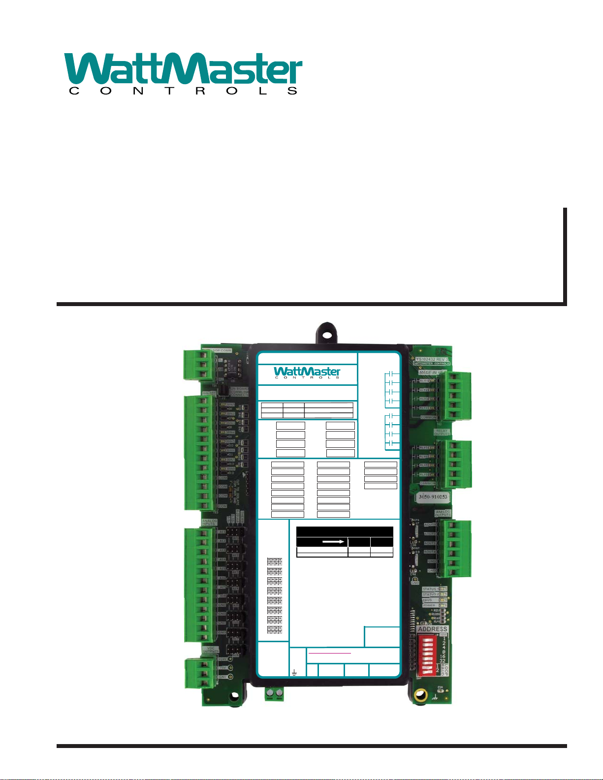
GPC-XP Controller
Technical Guide
RS-485 COMMUNICATION LOOP. WIRE
“R” TO “R”, “T” TO “T” “SHLD” TO “SHLD”
www.wattmaster.com
OE338-23-GPC-XP
GPC-XP CONTROLLER
RLY1 =
RLY2 =
RLY3 =
RLY4 =
AI1 =
AI2 = BI2 = AO2 =
AI3 = BI3 = AO3 =
AI4 = BI4 = AO4 =
AI5 = BI5 =
AI6 = BI6 =
AI7 = BI7 =
AI8 = BI8 =
ANALOG
INPUT
JUMPERS
4-20mA
0-5V
0-10V
AI1
AI2
AI3
AI4
AI5
AI6
AI7
AI8
VDC
OUTPUTS
+ 24 VDC
+ 5 VDC
GND
RLY5 =
RLY6 =
RLY7 =
RLY8 =
BI1 = AO1 =
THERM
NOTES:
1.) ANALOG INPUT JUMPER SETTINGS MUST BE
SET FOR YOUR SPECIFIC INPUT DEVICE
REQUIREMENT.
2.) IT IS RECOMMENDED THATYOU WRITE THE
DESCRIPTION OF THE INPUT,AND/OR
OUTPUTS YOU ARE CONNECTING TOTHE
CONTROLLER IN THE BOXES PROVIDED ABOVE
USING A PERMANENTMARKER (SHARPIE ) FOR
FUTURE REFERENCE.
24 VAC POWER ONLY
WARNING! POLARITY MUST BE OBSERVED
OR THE CONTROLLER WILL BE DAMAGED
GND
USB
E-BUS
PORT
+ 24 VAC
PORT
RELAY CONTACT
RATING IS 1AMP
MAX @ 24 VAC
RELAY1
RELAY2
RELAY3
RELAY4
COMMON
RELAY5
RELAY6
RELAY7
RELAY8
COMMON
®
WattMaster Label
#LB102095
Rev.: 1C
Page 2

Table of Contents
OVERVIEW ................................................................................................................................................. 3
Features ........................................................................................................................................................... 3
Step-By-Step Guide ......................................................................................................................................... 4
SECTION 1: GPC-XP WIRING & SETUP ................................................................................................... 5
Environmental Requirements ........................................................................................................................... 5
Mounting .......................................................................................................................................................... 5
Power Supply ................................................................................................................................................... 5
GPC-XP Controller Dimensions ....................................................................................................................... 5
GPC-XP Wiring ................................................................................................................................................ 6
Communication Settings .................................................................................................................................. 7
Addressing and Baud Rate Settings ................................................................................................................ 8
SECTION 2: INSTALLING PRISM 2........................................................................................................... 9
SECTION 3: GPC-XP NAVIGATION AND STATUS ................................................................................... 10
SECTION 4: CONFIGURING ANALOG INPUTS ....................................................................................... 12
SECTION 5: CONFIGURING BINARY INPUTS ........................................................................................ 17
SECTION 6: CONFIGURING RELAYS...................................................................................................... 20
SECTION 7: CONFIGURING ANALOG OUTPUTS ................................................................................... 28
SECTION 8: OUTDOOR STATUS & AVC STATUS ................................................................................... 34
SECTION 9: SETTING SCHEDULES ....................................................................................................... 35
SECTION 10: CONFIGURING ALARMS .................................................................................................. 39
SECTION 11: MISCELLANEOUS SETTINGS .......................................................................................... 40
SECTION 12: SAVING AND RESTORING SETPOINTS ............................................................................ 44
SECTION 13: TREND LOGGING AND PRINTING .................................................................................... 45
APPENDIX A: HELP SCREENS AND SAMPLE STATUS REPORT ............................................................ 48
APPENDIX B: USB DRIVER INSTALLATION ........................................................................................... 52
INDEX ...................................................................................................................................................... 54
2
www.wattmaster.com
WattMaster Controls, Inc.
8500 NW River Park Drive · Parkville, MO 64152
Toll Free Phone: 866-918-1100
PH: (816) 505-1100 · FAX: (816) 505-1101 ·
E-mail: mail@wattmaster.com
Visit our web site at www.wattmaster.com
WattMaster Controls, Inc. assumes no responsibility for errors
or omissions.
This document is subject to change without notice.
Form: WM-GPCXP-TGD-01E
Copyright May 2015 WattMaster Controls, Inc.
GPC-XP Controller Technical Guide
Page 3

Overview
GPC-XP Controller
Overview
The GPC-XP Controller ( OE338-23-GPC-XP) is used for controlling
equipment or processes that cannot be controlled using a standard
HVAC controller.
The GPC-XP provides the fl exibility to control, schedule and/or
monitor equipment such as unit heaters, exhaust fans, motorized
dampers, pumps, and other mechanical equipment. It can also be
used for simple boiler, chiller, or refrigeration applications as well
as to provide lead/lag start function.
The GPC-XP has an on-board CommLink that provides for standalone programming and monitoring via a direct USB connection to
a computer running Prism 2 software. If used on a networked system
that has an external CommLink, this on-board CommLink would
not be used. Alternatively, the System Manager Touch Screen II for
GPC-XP (OE392-10-GPCXP) can be used to
force modes, and set schedules.
The GPC-XP has (8) confi gurable analog inputs which will ac-
cept signals from thermistor temperature sensors or from 4-20mA,
0-5VDC, or 0-10VDC transmitters. The inputs are set for the desired
scaling by means of a jumper bar. Custom formulas created by
available math functions and operators can be used in conjunction
with the analog inputs to create a calculated value to be used and
displayed for a specifi c analog input. An additional modular input
is available for WattMaster communicating sensors.
view status, perform
Features
The GPC-XP Controller provides the following:
8 confi gurable analog inputs
8 wet contact binary inputs confi gured for normally open
or normally closed operation
8 relay outputs for on/off control
4 analog outputs for proportional or PID control signals
E-BUS port for communicating sensors
8 separate 2 events per day schedules which can be
assigned to any input or output for operational control or
alarm recognition based on time of day
Schedules can be confi gured to broadcast to other
WattMaster HVAC equipment installed on the same
communications loop as the GPC-XP
Can be confi gured using a computer with Prism 2
software installed
The System Manager Touch Screen II for GPC-XP (sold
separately) can be used to view status, perform force
modes, and set schedules.
The GPC-XP has (8) wet contact binary inputs that can be confi g-
ured for either normally open or normally closed operation. Also
available are (8) relay outputs for on/off control and (4) analog
outputs (0-10VDC) for modulating control. Highest/lowest/average
(H/L/A) of the analog input values can be used in the GPC-XP logic
or broadcast to other controllers on the control system loop. These
H/L/A values are referred to in this technical guide as AVC (Analog
Value Comparison) values.
There are (8) separate two events per day schedules which can be
assigned to any input or output for operational control or for alarm
recognition based on time of day. These schedules can also be confi gured to broadcast to other WattMaster controllers on the control
system loop.
NOTE: The internal USB communication port of the GPC-
XP Controller uses a specialized driver (USB Driver
CD-ROM included) that must be installed on your
Windows PC before communication to the device can
be established. To install the USB Driver, follow the
instructions in Appendix B on page 52.
Can be operated Stand-Alone or connected to a
networked system
On-board CommLink for Stand-Alone programming
using a USB connection to a computer running Prism 2
software
NOTE: The GPC-XP Controller contains no user-serviceable
parts. Contact qualifi ed technical personnel if your
Controller is not operating correctly.
GPC-XP Controller Technical Guide
3
Page 4

Overview
Step-By-Step Guide
Zone
Zone
Step-By-Step Guide
This guide will lead you through each step in confi guring your GPC-
XP Controller. Below is a quick overview of each step.
Section 1: GPC-XP Wiring & Setup—This section explains
how to mount and wire your GPC-XP properly. It also explains how
to set the address and baud rate for your particular system.
Section 2: Prism 2 Installation—This section explains how
to install Prism 2 software required to program your GPC-XP Controller. If you are not familiar with the Prism 2 software program,
please refer to the Prism 2 T echnical Guide which can be downloaded
from the Orion Controls website: www.orioncontrols.com.
Section 3: GPC-XP Personalization & Status—This sec-
tion explains how to individualize and access GPC-XP Controllers
when more than one is installed and also provides and overview of
the GPC-XP Controller Status Screen.
Section 4: Confi guring Analog Inputs—This section ex-
plains how to confi gure analog inputs, individualize analog input
descriptions, and calibrate thermistor sensors, and override and clear
other analog input values.
Section 5: Confi guring Binary Inputs—This section ex-
plains how to confi gure binary inputs, individualize binary input
descriptions, and override binary inputs.
Section 6: Confi guring Relays—This section explains how
to confi gure relay outputs and individualize relay descriptions.
Section 7: Confi guring Analog Outputs—This section
explains how to confi gure analog outputs, individualize analog output
descriptions, override voltages, and cancel overrides.
Section 8: Outdoor Status and AVC (Analog Value
Comparison) Status
and view AVC and Outdoor Status setpoints.
Section 9: Setting Schedules—This section describes how
to confi gure daily and holiday schedules and perform schedule force
modes.
Section 10: Confi guring Alarms—This section explains how
to confi gure and view alarms.
Section 11: Miscellaneous Settings—This section includes
miscellaneous settings for Week Schedule Broadcasts, AVC Inputs,
AVC Setpoints, Rouge Sensor Limits, Reset Rogue Sensor, Outdoor
Air Broadcasts, Trend Logging, and Daylight Savings.
Section 12: Saving and Copying Setpoints—This section
explains how to save GPC-XP setpoints to a fi le on your computer
and how to restore GPC-XP setpoints once you have saved them
to a fi le.
Section 13: Viewing and Printing Trend Logs—This
section explains how to view and print Trend Logs.
Appendix A—This appendix provides Help Screen information.
Appendix B—This appendix explains USB Driver Installation.
—This section explains how to confi gure
Index—The index provides page numbers for easy reference to
quickly fi nd the information you need.
4
GPC-XP Controller Technical Guide
Page 5
Section 1: GPC-XP Wiring & Setup
Dimensions and Mounting
Environmental Requirements
The GPC-XP Controller needs to be installed in an environment that
can maintain a temperature range between -30°F and 150°F and not
exceed 90% RH levels (non-condensing).
Mounting
The GPC-XP Controller is housed in a plastic enclosure. It is designed to be mounted by using the 3 mounting holes in the enclosure
base. It is important to mount the module in a location that is free
from extreme high or low temperatures, moisture, dust, and dirt. Be
careful not to damage the electronic components when mounting
the module.
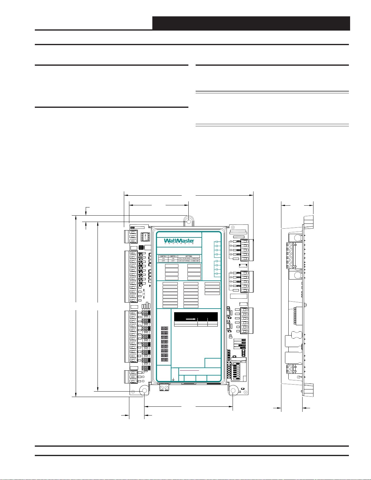
See Figure 1 for Controller dimensions (in inches).
5.985.98
2.752.75
T-
SH
R+
BIN1
D6
BIN2
D7
BIN3
D8
BIN4
D9
BIN5
D10
BIN6
D11
BIN7
D12
BIN8
D13
COM
COM
COM
COM
0-5v
AI1
AI2
AI3
AI4
AI5
AI6
AI7
AI8
GND
GND
GND
GND
+24V
+5V
GND
RS-485 COMMUNICATION LOOP. WIRE
“R” TO “R”, “T” TO“T” “SHLD” TO “SHLD”
ON BOA
COMMLI
CONNEC
0-10v
AI1
AI2
AI3
AI4
AI5
AI6
AI7
AI8
R38
300
R41
300
R43
300
R47
300
300
300
300
R61R59R55R51
300
CUTTO ISOLATE
COMFROM GND
4-20mA
THERM
www.wattmaster.com
OE338-23-GPC-XP
GPC-XP CONTROLLER
RLY1 =
RLY2 =
RLY3 =
RLY4 =
AI1 =
AI2 = BI2 = AO2 =
AI3 = BI3 = AO3 =
AI4 = BI4 = AO4 =
AI5 = BI5 =
AI6 = BI6 =
AI7 = BI7 =
AI8 = BI8 =
ANALOG
INPUT
JUMPERS
4-20mA
0-10V
0-5V
THERM
AI1
AI2
AI3
AI4
AI5
AI6
AI7
AI8
VDC
OUTPUTS
+ 24 VDC
+ 5 VDC
GND
RLY5 =
RLY6 =
RLY7 =
RLY8 =
BI1 = AO1 =
LED NAME STATUS1 STATU S2
NORMAL OP ERATION 0 1
SCHEDULE OVERRIDE 0 2
NOTES:
1.) ANALOG INPUTJUMPER SETTINGS MUST BE
SET FOR YOUR SPECIFIC INPUT DEVICE
REQUIREMENT.
2.) IT IS RECOMMENDED THATYOU WRITE THE
DESCRIPTION OF THE INPUT,AND/OR
OUTPUTS YOUARE CONNECTING TO THE
CONTROLLER IN THE BOXES PROVIDEDABOVE
USING APERMANENT MARKER (SHARPIE) FOR
FUTURE REFERENCE.
24 VAC POWER ONLY
WARNING!POLARITY MUST BE OBSERVED
OR THE CONTROLLER WILL BE DAMAGED
GND
+24VAC
8.388.38
0.290.29
7.837.83
BINARY
INPUTS
ANALOG
INPUTS
VDC
OUTPUTS
LOOPCOMM
TB1
TB3
TB7
TB8
Power Supply
The GPC-XP Controller requires a 24 VAC power connection with
a minimum rating of 8 VA.
WARNING: Observe polarity! All boards must be wired
GND-to-GND and 24 VAC-to-VAC. Failure to
observe polarity could result in damage to the
boards.
1.49
YS102432 REV 3
WATTMASTER CONTROLS
MADE IN USA
RLY1
RLY2
RLY3
RLY4
COMMON
RLY1
RLY2
RLY3
RLY4
COMMON
SERIAL #
1002
R74
U17
AOUT1-2
.1uF
C36
1002
R97
U19
AOUT3-4
.1uF
C46
GND
STATUS1
STATUS2
EBUS
POWER
.1uF
ADDRESS
1002
1002
1002
1002
1002
1002
1002
1002
SW1
TB2
RELAY
OUTPUTS
TB4
ANALOG
OUTPUTS
AOUT1
AOUT2
AOUT3
AOUT4
GND
GND
TB6
1002
R21
1002
R109
1002
R16
1002
R14
C21
ADD
1
2
4
8
16
32
LOOP
BAUD
1
2
C14
.01uF
LED BLINK C ODES
USB
E-BUS
PORT
PORT
RELAYCONTACT
RATING IS 1AMP
MAX @ 24 VAC
RELAY1
RELAY2
RELAY3
RELAY4
COMMON
RELAY5
RELAY6
RELAY7
RELAY8
COMMON
®
WattMaster Label
#LB102095
Rev.: 1C
0.700.70
Figure 1: GPC-XP Dimensions
GPC-XP Controller Technical Guide
4.104.10
0.980.98
5
Page 6
Section 1: GPC-XP Wiring & Setup
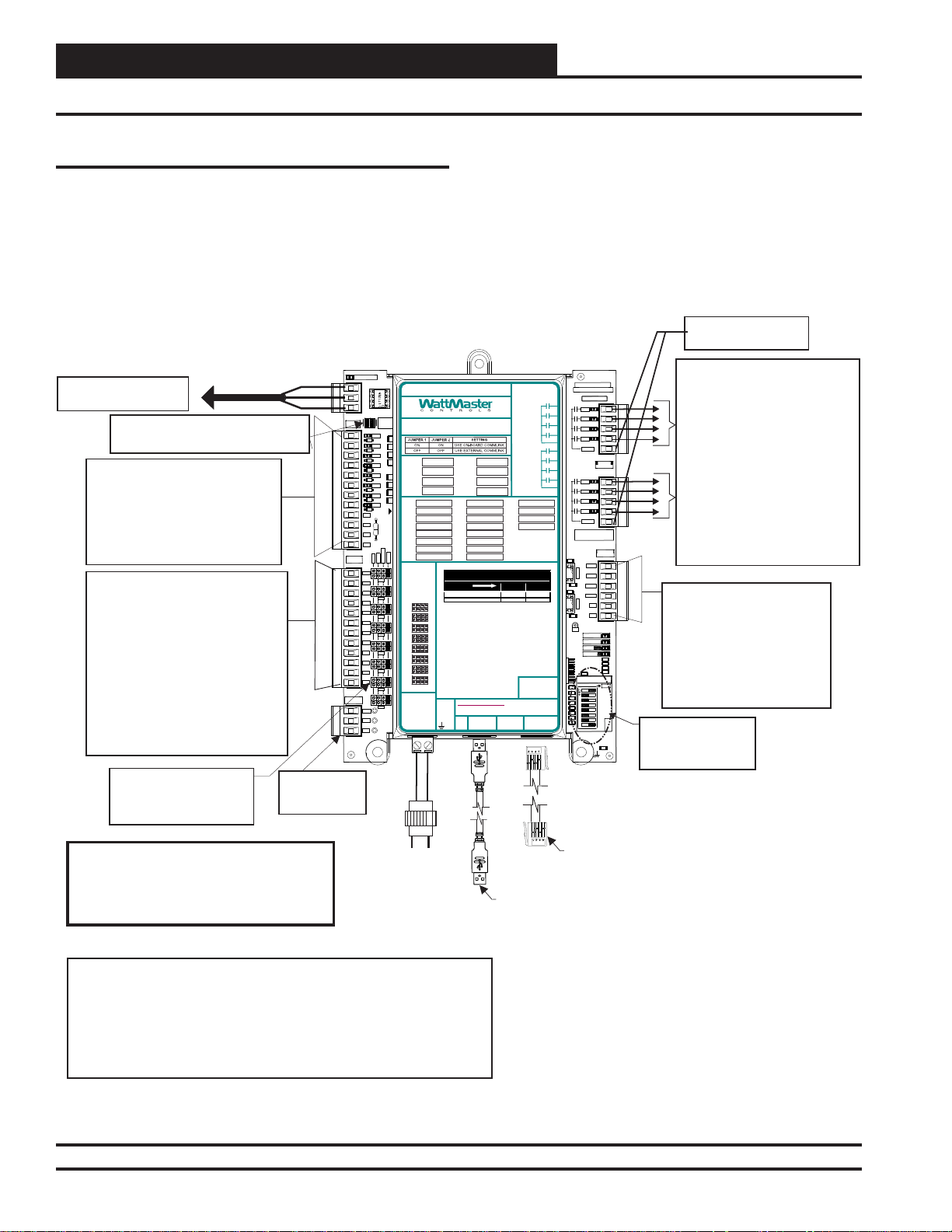
Installation & Wiring
Important Wiring Considerations
Please read carefully and apply the following information when
wiring the GPC-XP Controller:
1. To operate the GPC-XP Controller, you must connect power to
the 24 VAC input terminal block.
All Communication Loop Wiring Is
Straight Through
T To T, R To R, SHLD To SHLD
Local Loop RS-485
Connect To Next Device
On The Local Loop
CommLink Jumpers
Both On = Use On Board CommLink
Both Off - Use External CommLink
Binary Inputs BIN1Through BIN8
Configured for The Following:
1. Not Used
2. Normally Closed Operation
3. Normally Open Operation
4. Read Global Binary
5. Push-Button Override
6. Follow Relay
Analog Inputs AI1Through AI8
Configured For the Following:
1. Thermistor 10K Ohm Type III
Temperature Sensors (Fahrenheit)
2. Thermistor 10K Ohm Type III
Temperature Sensors (Celsius)
3. 4 - 20mA User Scaled
4. 0 - 5 vdc User Scaled
5. Wall Sensor Slide Offset
6. Read Global Analog Broadcast from
another Controller
7. Communicating Temperature Sensor
8. Communicating Humidity Sensor
9. Communicating Carbon Dioxide
Jumpers - Typical
Jumpers Must Be Set
Correctly For The Type Of
Input You Require.
9600 Baud
BINARY
INPUTS
ANALOG
INPUTS
VDC
OUTPUTS
5 VDC & 24VDC
Power For
Sensors
LOOPCOMM
T-
SH
R+
TB1
COM
COM
COM
COM
TB3
GND
GND
GND
GND
TB7
+24V
+5V
GND
TB8
BIN1
D6
BIN2
D7
BIN3
D8
BIN4
D9
BIN5
D10
BIN6
D11
BIN7
D12
BIN8
D13
0-5v
AI1
AI2
AI3
AI4
AI5
AI6
AI7
AI8
OE338-23-GPC-XP
GPC-XP Controller
RS-485 COMMUNICATION LOOP. WIRE
“R” TO “R”, “T”TO “T” “SHLD” TO “SHLD”
www.wattmaster.com
OE338-23-GPC-XP
GPC-XP CONTROLLER
300
300
300
300
RLY1 =
RLY2 =
300
RLY3 =
300
RLY4 =
300
300
AI1 =
AI2 = BI2 = AO2 =
AI3 = BI3 = AO3 =
AI4 = BI4 = AO4 =
AI5 = BI5 =
AI6 = BI6 =
AI7 = BI7 =
THERM
AI8 = BI8 =
ANALOG
INPUT
JUMPERS
4-20mA
0-10V
0-5V
THERM
AI1
AI2
AI3
AI4
AI5
AI6
AI7
AI8
VDC
OUTPUTS
+ 24VDC
+ 5VDC
GND
GND
24 VAC
GND
0-10v
ON BOA
COMMLI
CONNEC
COMFROM GND
AI1
AI2
AI3
AI4
AI5
AI6
AI7
AI8
R38
R41
R43
R47
R61R59R55R51
CUTTO ISOLATE
4-20mA
2. Check all wiring leads at the terminal block for tightness.
Be sure that wire strands do not stick out and touch adjacent
terminals. Confi rm that all sensors required for your system are
mounted in the appropriate location and wired into the correct
terminals. See Figure 2 below for wiring.
24VAC Power
For Relay Outputs
RELAYCONTACT
RATING IS 1AMP
MAX @ 24 VAC
RELAY1
RELAY2
RELAY3
RELAY4
COMMON
RELAY5
LED BLINK CODES
USB
E-BUS
PORT
PORT
RELAY6
RELAY7
RELAY8
COMMON
WattMaster Label
®
#LB102095
Rev.: 1C
RLY5 =
RLY6 =
RLY7 =
RLY8 =
BI1 = AO1 =
LED NAME STATU S1 STATUS2
NORMAL OPERATI ON 0 1
SCHEDULE OVERRIDE 0 2
NOTES:
1.)ANALOG INPUT JUMPER SETTINGS MUST BE
SET FOR YOUR SPECIFIC INPUTDEVICE
REQUIREMENT.
2.) IT IS RECOMMENDED THATYOU WRITE THE
DESCRIPTION OF THE INPUT,AND/OR
OUTPUTS YOUARE CONNECTING TO THE
CONTROLLER IN THE BOXES PROVIDEDABOVE
USINGA PERMANENT MARKER (SHARPIE) FOR
FUTURE REFERENCE.
24 VAC POWER ONLY
WARNING!POLARITY MUST BE OBSERVED
OR THE CONTROLLER WILL BE DAMAGED
+24VAC
YS102432 REV 3
WATTMASTER CONTROLS
MADE IN USA
RLY1
RLY2
RLY3
RLY4
COMMON
RLY1
RLY2
RLY3
RLY4
COMMON
SERIAL #
1002
R74
U17
AOUT1-2
.1uF
C36
R97
1002
U19
AOUT3-4
.1uF
C46
GND
STATUS1
STATUS2
EBUS
POWER
.1uF
ADDRESS
1002
1002
1002
1002
1002
1002
1002
1002
SW1
TB2
RELAY
OUTPUTS
TB4
ANALOG
OUTPUTS
AOUT1
AOUT2
AOUT3
AOUT4
GND
GND
TB6
1002
R21
1002
R109
1002
R16
1002
R14
C21
ADD
1
2
4
8
16
32
LOOP
BAUD
1
2
C14
.01uF
8 Relay Outputs Are Available For
On/Off Control Of Equipment
Configured For the Following:
1. Not Configured
2. On Above / Off Below
3. On Above / On Below
4. Off Above / On Below
5. Off Above / Off Below
6. Follow Active Binary Input
7. Follow Inactive Binary Input
8. Follow Relay Output
9. Follow Schedule
10. Ventilation Control
11. Lead Relay for Lead/Lag Control
12. Lag Relay for Lead/Lag Control
Analog Outputs AOUT1 through
AOUT4 Provide (4) 0-10 VDC
Outputs Configured For The
Following:
1. Not Configured
2. Direct Acting Floating Point
3. Reverse Acting Floating Point
4. Direct Acting PID
5. Reverse Acting PID
ADDRESS Dipswitch
is Used for Setting
the Address and
Baud Rate.
Line Voltage
Warning:
24 VAC Must Be Connected So That All
Ground Wires Remain Common. Failure To
Do So Will Result In Damage To The
Controller
NOTES:
1.)24 VAC Must Be Connected So
That All Ground Wires Remain
Common.
2.)All Wiring To Be In Accordance With
Local And National Electrical Codes
and Specifications.
3.)All Communication Wiring To Be 18
Ga. Minimum, 2 Conductor Twisted
Pair With Shield. Belden #82760 Or
Equivalent.
4.)It Is Recommended That The
Address Switch Is Set Before
Installation.
Figure 2: GPC-XP Controller Wiring Diagram
6
24 VAC
Transformer
8 VA
Minimum
EBC E-BUS Cable
Connect to
Communicating Sensor
USB Cable
Connect to Computer with
Prism II Software Installed For
Stand-Alone Programming
GPC-XP Controller Technical Guide
Page 7
Section 1: GPC-XP Wiring & Setup
Communication Settings
Before Applying Power
In order to have a trouble free start-up, it is important to follow a
few simple procedures. Before applying power for the fi rst time, it
is very important to correctly address the controller and run through
a few simple checks.
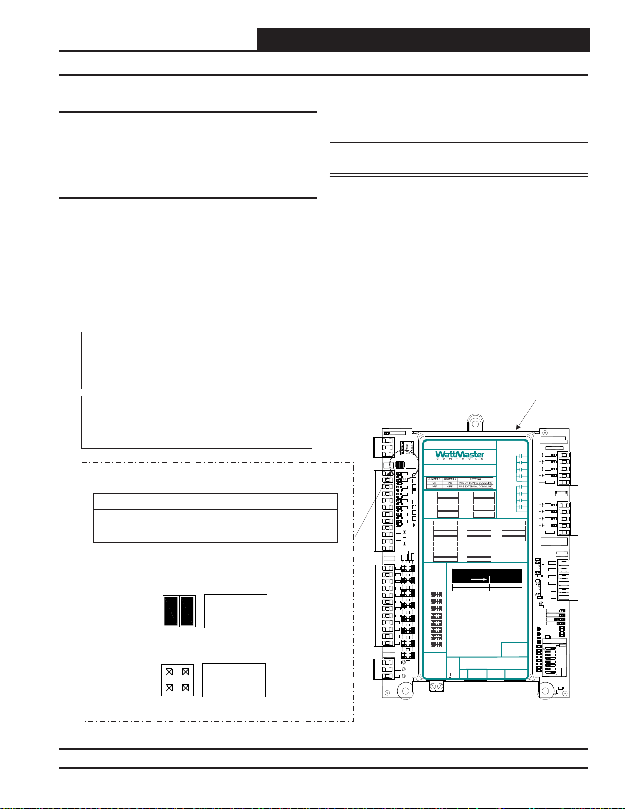
Communication Settings
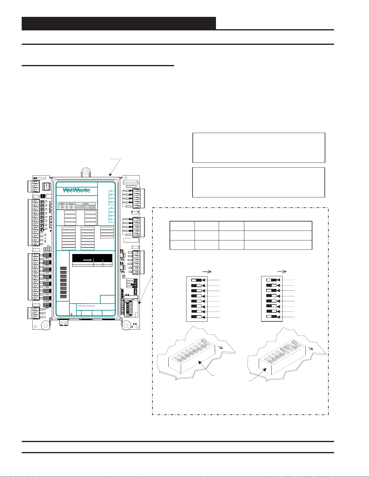
Stand Alone Operation
The GPC-XP has an on-board CommLink that is used during StandAlone Operation. When confi gured for Stand-Alone operation, a
computer running Prism 2 software can be connected directly to the
USB port located at the bottom of the GPC-XP for programming
and monitoring. In order to operate in Stand-Alone Mode, two
things need to be set. First, both CommLink Jumpers found on the
upper left hand side of the board need to be set to ON. See Figure
Caution:
Disconnect All Communication Loop Wiring From The
Controller Before Removing Power From The Controller.
Reconnect Power And Then Reconnect Communication
Loop Wiring.
3 below for details. Second, the Baud Rate determined by setting
ADDRESS Dipswitches 7 and 8 needs to be set to OFF/ON. See
Figure 4, page 8 for details.
NOTE: If using the Internal CommLink, you must set up
the USB drivers. See Appendix B, page 52.
Network Operation
The GPC-XP can be confi gured for connection to a networked system
that has an external CommLink. In this case, the on-board CommLink
would not be used. For this confi guration, two things need to be set.
First, both CommLink Jumpers found on the upper left found on the
upper left hand side of the board need to be set to OFF. See Figure
3 below for details. Second, the Baud Rate determined by setting
ADDRESS Dipswitches 7 and 8 needs to be set to OFF/OFF if using a CommLink IV and to OFF/ON if using a CommLink 5. See
Figure 4, page 8 for details.
Note:
The Power To The Controller Must Be Removed And
Reconnected After Changing The Address Switch
Settings In Order For Any Changes To Take Effect.
ON-BOARD COMMLINK SETTING
Jumper 1
ON
OFF
Jumper 2
ON
OFF
Both Jumpers ON
Use On-Board CommLink
Use External CommLink
Setting
ON BOARD
COMMLINK
CONNECT
Both Jumpers OFF
ON BOARD
COMMLINK
CONNECT
BINARY
INPUTS
ANALOG
INPUTS
VDC
OUTPUTS
LOOPCOMM
T-
SH
R+
TB1
COM
COM
COM
COM
TB3
GND
GND
GND
GND
TB7
+24V
+5V
GND
TB8
RS-485 COMMUNICATION LOOP. WIRE
“R” TO “R”, “T”TO “T” “SHLD” TO “SHLD”
ON BOA
COMMLI
CONNEC
R38
BIN1
300
D6
R41
BIN2
300
D7
R43
300
BIN3
R47
D8
300
BIN4
RLY1 =
D9
BIN5
300
RLY2 =
D10
300
BIN6
RLY3 =
D11
300
BIN7
RLY4 =
R61R59R55R51
D12
300
BIN8
AI1 =
D13
AI2 = BI2 = AO2 =
CUTTO ISOLATE
COMFROM GND
AI3 = BI3 = AO3 =
AI4 = BI4 = AO4 =
AI5 = BI5 =
AI6 = BI6 =
4-20mA
THERM
0-10v
AI7 = BI7 =
0-5v
AI8 = BI8 =
AI1
AI2
AI3
AI4
AI5
AI6
AI7
AI8
ANALOG
AI1
INPUT
JUMPERS
AI2
0-5V
AI1
AI3
AI2
AI3
AI4
AI4
AI5
AI5
AI6
AI6
AI7
AI8
AI7
VDC
OUTPUTS
AI8
+ 24 VDC
+ 5 VDC
GND
GPC-XP Controller
RELAYCONTACT
RATING IS 1AMP
MAX @ 24 VAC
www.wattmaster.com
OE338-23-GPC-XP
GPC-XP CONTROLLER
RLY5 =
RLY6 =
RLY7 =
RLY8 =
BI1 = AO1 =
LED NAME STATUS1 STATU S2
NORMAL OP ERATION 0 1
SCHEDULE OVERRIDE 0 2
4-20mA
0-10V
THERM
NOTES:
1.)ANALOG INPUT JUMPER SETTINGS MUST BE
SET FOR YOUR SPECIFIC INPUTDEVICE
REQUIREMENT.
2.) IT IS RECOMMENDED THATYOU WRITE THE
DESCRIPTION OF THE INPUT,AND/OR
OUTPUTS YOUARE CONNECTING TO THE
CONTROLLER IN THE BOXES PROVIDEDABOVE
USINGA PERMANENT MARKER (SHARPIE) FOR
FUTURE REFERENCE.
24 VAC POWER ONLY
WARNING!POLARITY MUST BE OBSERVED
OR THE CONTROLLER WILL BE DAMAGED
GND
+24VAC
LED BLINK CO D ES
USB
E-BUS
PORT
PORT
COMMON
COMMON
RELAY1
RELAY2
RELAY3
RELAY4
RELAY5
RELAY6
RELAY7
RELAY8
WattMaster Label
®
#LB102095
Rev.: 1C
YS102432 REV 3
WATTMASTER CONTROLS
RLY1
RLY2
RLY3
RLY4
COMMON
RLY1
RLY2
RLY3
RLY4
COMMON
SERIAL #
1002
R74
U17
AOUT1-2
.1uF
C36
R97
1002
U19
AOUT3-4
.1uF
C46
GND
.1uF
ADDRESS
1002
1002
1002
1002
1002
1002
1002
1002
SW1
MADE IN USA
AOUT1
AOUT2
AOUT3
AOUT4
GND
GND
STATUS1
STATUS2
EBUS
POWER
C21
R109
TB2
RELAY
OUTPUTS
TB4
ANALOG
OUTPUTS
TB6
R21
R16
R14
1002
1002
1002
1002
ADD
1
2
4
8
16
32
LOOP
BAUD
1
2
C14
.01uF
Figure 3: GPC-XP Controller Address Switch Setting
GPC-XP Controller Technical Guide
7
Page 8
Section 1: GPC-XP Wiring & Setup
Addressing and Baud Rate Settings
Zone
Zone
Controller Addressing and Baud Rate
The GPC-XP Controller is equipped with address switches. When
using Prism 2 to program and confi gure the GPC-XP Controller, you
would enter this address to communicate with the controller. When
the system is to be connected to other HVAC unit controllers on a
communication loop, each controller’s address switch must be set
with a unique address between 1 and 59.
GPC-XP Controller
BINARY
INPUTS
ANALOG
INPUTS
VDC
OUTPUTS
LOOPCOMM
T-
SH
R+
TB1
COM
COM
COM
COM
TB3
GND
GND
GND
GND
TB7
+24V
+5V
GND
TB8
RS-485 COMMUNICATION LOOP. WIRE
“R” TO “R”, “T”TO “T” “SHLD” TO “SHLD”
ON BOA
COMMLI
CONNEC
R38
BIN1
300
D6
R41
BIN2
300
D7
R43
300
BIN3
R47
D8
300
RLY1 =
BIN4
D9
RLY2 =
BIN5
300
D10
RLY3 =
300
BIN6
D11
300
RLY4 =
BIN7
R61R59R55R51
D12
300
AI1 =
BIN8
D13
AI2 = BI2 = AO2 =
CUTTO ISOLATE
COMFROM GND
AI3 = BI3 = AO3 =
AI4 = BI4 = AO4 =
AI5 = BI5 =
AI6 = BI6 =
4-20mA
AI7 = BI7 =
THERM
0-10v
0-5v
AI8 = BI8 =
AI1
AI2
AI3
AI4
AI5
AI6
AI7
AI8
ANALOG
INPUT
AI1
JUMPERS
AI2
0-5V
AI1
AI3
AI2
AI3
AI4
AI4
AI5
AI5
AI6
AI7
AI6
AI8
AI7
VDC
OUTPUTS
AI8
+ 24VDC
+ 5VDC
GND
www.wattmaster.com
OE338-23-GPC-XP
GPC-XP CONTROLLER
RLY5 =
RLY6 =
RLY7 =
RLY8 =
BI1 = AO1 =
LED BLINK CODES
LED NAME STATUS1 STATUS2
NORMAL OPERATI ON 0 1
SCHEDULE O VERRIDE 0 2
4-20mA
0-10V
THERM
NOTES:
1.)ANALOG INPUT JUMPER SETTINGS MUST BE
SET FOR YOUR SPECIFIC INPUTDEVICE
REQUIREMENT.
2.) IT IS RECOMMENDED THATYOU WRITE THE
DESCRIPTION OF THE INPUT,AND/OR
OUTPUTS YOUARE CONNECTING TO THE
CONTROLLER IN THE BOXES PROVIDEDABOVE
USINGA PERMANENT MARKER (SHARPIE) FOR
FUTURE REFERENCE.
24 VAC POWER ONLY
WARNING!POLARITY MUST BE OBSERVED
OR THE CONTROLLER WILL BE DAMAGED
GND
USB
PORT
+24VAC
E-BUS
PORT
RELAYCONTACT
RATING IS 1AMP
MAX @ 24 VAC
RELAY1
RELAY2
RELAY3
RELAY4
COMMON
RELAY5
RELAY6
RELAY7
RELAY8
COMMON
WattMaster Label
#LB102095
Rev.: 1C
YS102432 REV 3
WATTMASTER CONTROLS
MADE IN USA
RLY1
RLY2
RLY3
RLY4
COMMON
TB2
RELAY
OUTPUTS
TB4
RLY1
RLY2
RLY3
RLY4
COMMON
SERIAL #
ANALOG
OUTPUTS
1002
R74
U17
AOUT1
AOUT1-2
AOUT2
.1uF
AOUT3
C36
R97
1002
AOUT4
U19
AOUT3-4
GND
GND
.1uF
C46
TB6
GND
STATUS1
STATUS2
EBUS
1002
1002
1002
1002
1002
1002
1002
1002
SW1
POWER
.1uF
C21
ADDRESS
1002
R21
1002
R109
1002
R16
1002
R14
ADD
1
2
4
8
16
32
LOOP
BAUD
1
2
C14
.01uF
®
Address 1 @ 9600 Baud
Address switches 7 and 8 are used for the baud rate selection. See
Figure 4
below for address switch and baud rate setting information.
Caution:
Disconnect All Communication Loop Wiring From The
Controller Before Removing Power From The Controller.
Reconnect Power And Then Reconnect Communication
Loop Wiring.
Note:
The Power To The Controller Must Be Removed And
Reconnected After Changing The Address Switch
Settings In Order For Any Changes To Take Effect.
BAUD RATE SELECTION
Baud
9600
57600
Switch 7 Switch 8
OFF
OFF
OFF
ON
Communication Setting
CommLink IV
CommLink 5 & Stand Alone
Address 5 @ 57,600 Baud
ADD
1
2
4
8
16
32
Baud 0
Baud 1
ADD
1
2
4
8
16
32
Baud 0
Baud 1
Figure 4: GPC-XP Controller Address Switch Setting
8
ADD
Address Switch Shown Is
Set For Address 1
The Address For Each Controller
Must Be Unique To The Other Controllers
On The Local Loop And Be Between 1 and 59
GPC-XP Controller Technical Guide
ADD
Controller
Address Switch
Address Switch Shown Is
Set For Address 13
Page 9

Section 2: Installing Prism 2
Initialization, Prism 2 Software, and SMTS II for GPC-XP
Initialization
On system power up, there is an approximately 30-second startup
delay where all default setpoints are initialized, LED’s are initialized,
and all outputs are turned off.
When power is fi rst applied, the STATUS1 LED will fl ash intermit-
tently for about 10 seconds. After a short pause, STATUS1 LED
and STATUS2 LED will fl ash out the controller address. STATUS1
LED will fl ash to represent the tens position. STATUS2 LED will
fl ash to represent the ones position. After the controller address is
complete, there will be a short pause while the initialization process
is completed. There will be no controller operation or communications during initialization. After initialization, STATUS2 LED will
continuously fl ash the status code—(1) blink indicates Normal
Operation; (2) blinks indicates a Push-Button Schedule Override
is in effect.
Example of a controller address of 25:
STATUS1 LED will fl ash 2 times. STATUS2 LED will fl ash 5 times.
Prism 2 Software
The next step is programming the controller for your specifi c re-
quirements. Initial programming of the GPC-XP must fi rst be done
with a personal computer using our Prism 2 software.
gives you access to the status, confi guration, and setpoint screens of
the GPC-XP Controller. The software is distributed on CD or can
be downloaded for free from our website: www.wattmaster.com/
techsupport. Prism 2 does not require any license agreement and
may be freely copied and distributed. See Figure 5 below.
For more information, please see the Prism 2 Technical Guide to
familiarize yourself with the program.
System Requirements
To use Prism 2 you must have a computer that meets or exceeds the
following requirements:
Operating System
• Microsoft
Windows
NOTE: Prism 2 is not intended for a server/client
environment.
®
Windows® 2000/ Windows® Vista,
®
7, or Windows® 8
Prism 2 software
* NOTE: The GPC-XP has a built-in CommLink that can
be utilized in Stand-Alone Mode. See page 7 for setting up
Stand-Alone a nd Network operations. In Network Mode,
you must have a CommLink IV or CommLink 5 installed in
order to communicate between your computer and the system. If remote communication is required, a WattMaster IP-
Module (Ether net) must also be installed in the CommLink.
System Manager Touc h Screen II for GPC-XP
The OE392-10-GPCXP System Manager TS II (Touch Screen)
for the GPC-XP provides a direct, graphic-enhanced, menu-driven
link to enable you to view the status, perform force modes, and set
schedules for your GPC-XP Controller. See Figure 5 below. For
more information, please see the System Manager TS II for GPC-
XP Technical Guide.
Support Information
WattMaster Controls provides Prism 2 installation and confi guration
support. Call (866) 918-1100 for free, direct telephone support or
(816) 505-1100 to talk to a Technical Support Representative. Support for all telephone services is available Monday through Friday,
7:00 AM to 5:00 PM central standard time.
NOTE: WattMaster Controls Technical Support can-
not troubleshoot internal PC and/or Windows®-based
operating system problems.
NOTE: WattMaster Controls Technical Support can-
not troubleshoot fi rewalls, r oute rs, a nd/o r p robl ems
on a customer’s internal or external network. An IT
professional may need to be consulted.
Operator
Interfaces
Minimum Hardware
• Windows
®
compatible computer
• Pentium 2 GHz Processor (Pentium 4 2 GHz or
greater,
Recommended)
• 1 GB RAM or greater)
• 120 MB hard drive space
• XVGA (1024 x 768) adapter and monitor
(1280 x 1024, Recommended)
• Network card for TCP/IP connection when IP
Module is used
• CommLink*
GPC-XP Controller Technical Guide
System Manager TS II
for GPC-XP
Computer & CommLink
with Prism 2 Software Installed
Figure 5: GPC-XP Operator Interfaces
9
Page 10
Section 3: GPC-XP Navigation & Status
Unit Selection
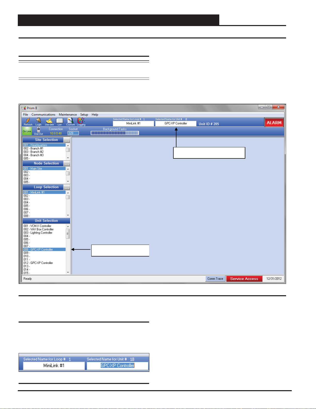
Selecting and Naming GPC-XP Controllers
Selecting GPC-XP Controllers
NOTE: See the Prism 2 Technical Guide for instructions on
setting up the job site and doing a search for units.
From the Prism 2 Main Screen, click on the GPC-XP Controller
address in the Unit Selection Window. In this example, it is address
18. See Figure 6 below.
Selected Name Dialog Box
Figure 6: Prism 2 Main Screen GPC-XP Controller Selection
Naming GPC-XP Controllers
If you have more than one GPC-XP Controller, you can rename it
in the Selected Name Dialog Box. See Figure 7 below. Many users
name their GPC-XP Controller according to the application that it
performs.
Figure 7: Naming the GPC-XP Controller
10
GPC-XP Controller Technical Guide
Page 11
Section 3: GPC-XP Navigation & Status
GPC-XP Controller Status Screen
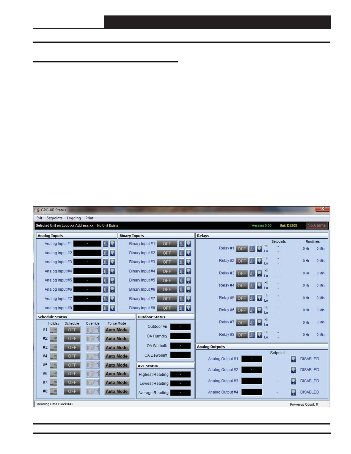
GPC-XP Controller Status Screen
Figure 8 below depicts the GPC-XP Controller Status Screen when
you fi rst access it with the Prism 2 program before any data has
been entered.
The screen is divided into separate windows as follows: Analog
Inputs Window, Binary Inputs Window, Relays Window, Analog
Outputs Window, Outdoor Status Window, AVC Status Window,
Schedule Status Window, and Alarms.
The GPC-XP Controller Status Screen Toolbar also gives you the
options to access the Miscellaneous Setpoints Screen, Save and
Restore Setpoints, View and Print Trend Logs, and Print a Status
Report for the current day.
The GPC-XP Controller Status Screen provides real-time live up-
dates of the current operating conditions and is used to access the
various setpoint and confi guration options.
No control takes place until the you confi gure the operation of the
GPC-XP Controller..
Once you confi gure your inputs, outputs, and operating schedules,
everything you need to monitor your GPC-XP is found on this GPC-
XP Controller Status Screen.
The rest of this technical guide explains each component on this
screen and provides detailed instructions for confi guring the data.
The following is a list of topics and their page numbers:
Analog Inputs Window, page 12
Binary Inputs Window, page 17
Relays Window, page 20
Analog Outputs Window, page 28
Outdoor Status Window, page 34
AVC Status Window, page 34
Schedule Status Window, page 35
Confi guring Alarms, page 39
Figure 8: GPC-XP Controller Status Screen
GPC-XP Controller Technical Guide
11
Page 12
Section 4: Confi guring Analog Inputs
Components and Navigation
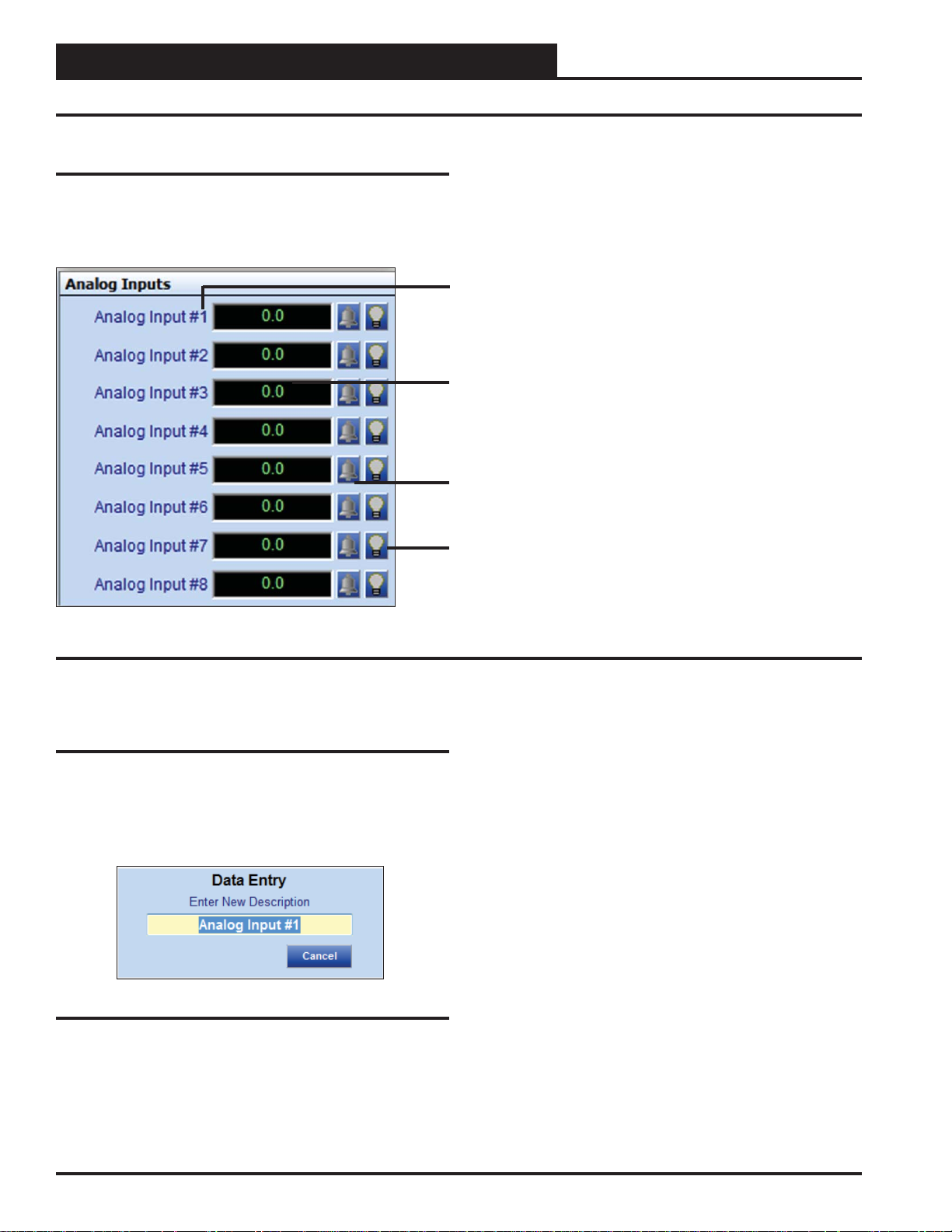
Analog Inputs
The Analog Inputs Window is located in the upper left-hand side of
the GPC-XP Controller Status Scr een (Figure 8, page 11). There are
8 Analog Inputs. See Figure 9 below for the Analog Inputs Window
component summary and the pages that follow for details.
Right or Left-click on any of the Analog Input name
fi elds to access the description entry box to add or
change the name of the Analog Input.
Left-Click in the data entry fi eld to confi gure the Analog
Input.
Right-Click on these fi elds to access the Calibration,
Override, and Clear Override.
The bell will light up to indicate that an alarm is on.
The Light bulb will light up when the Input is in the
Occupied Mode.
Figure 9: Analog Input Window Components and Navigation
Renaming Analog Inputs
To give an Analog Input a new name, click on the blue highlighted
Analog Input # fi eld and the Analog Input Data Entry Dialog Box
will open. See Figure 10 below. Once you have typed in a new
description, press
characters is 17.
<ENTER> to save. The maximum number of
Figure 10: Analog Input Data Entry Dialog Box
12
GPC-XP Controller Technical Guide
Page 13
Section 4: Confi guring Analog Inputs
Confi guring Analog Inputs
Left-click in the data entry fi eld in the Analog Inputs Window to
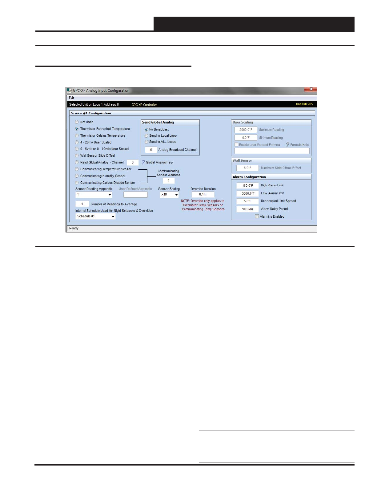
open the Analog Input Confi guration Window (Figure 11 below).
Analog Input Confi guration Screen
Figure 11: Analog Input Confi guration Window
The following confi gurations are available for each Analog Input:
Not Used
●
●
Thermistor Fahrenheit Temperature: 10K Ohm Type III
Scaled for Fahrenheit. Set jumper to the appropriate setting
(Figure 2, page 6.)
Thermistor Celsius Temperature: 10K Ohm Type III
●
Scaled for Celsius. Set jumper to the appropriate setting
(Figure 2, page 6.)
4 - 20mA User Scaled: 4-20mA User-Scaled Sensor
●
0 - 5vdc or 0-10 vdc User Scaled: Select this option
●
if using a 0-5vdc or 10vdc scaled sensor. Set jumper
associated with this input to the appropriate 0-5v or 0-10v
setting (Figure 2, page 6.)
Wall Sensor Slide Offset: If using a WattMaster
●
thermistor space sensor with the slide adjust, this would be
the input confi guration for the AUX connection from that
sensor.
Read Global Analog – Channel: See Figure 110, page
●
48 for an explanation of Analog Globals. Left or right click
on the Question mark beside Global Analog Help to access
information about the Global Broadcasts and to view predefi ned channels.
Communicating Temperature Sensor: If using a
●
WattMaster Communicating Temperature Sensor with a
modular cable, confi gure this input to read the appropriate
Communicating Sensor Address. Enter an address from
1-8 in the < Communicating Sensor Address> fi eld and
press <ENTER>. If using a combination Temperature and
Humidity Communicating Sensor, confi gure one input to
read the temperature and another input to read the humidity,
both using the same Communicating Sensor address.*
Communicating Humidity Sensor: If using a
●
combination Temperature and Humidity Communicating
Sensor with a modular cable, confi gure one input to read
the temperature and another input to read the humidity,
both using the same Communicating Sensor address. Enter
an address from 1-8 in the <Communicating Sensor
Address>
●
Communicating Carbon Dioxide Sensor: If using a
WattMaster Communicating CO2 Sensor with a modular
cable, confi gure this input to read the appropriate Comm-
unicating Sensor Address. Enter an address from 1-8 in
the <Communicating Sensor Address> fi eld and press
<ENTER>.*
●
Communicating Combination Outdoor Air Temperature
and Humidity Sensor:
unicating Combination Outdoor Air Temperature and
Humidity Sensor, confi gure one input to read the temperature
and another input to read the humidity. For each input, enter
<25> as the Communicating Sensor Address. Only one of
these sensors can be used on a GPC-XP.
*NOTE: See the appropriate E-BUS Digital Room Sensor or
fi eld and press <ENTER>.*
If using a WattMaster Comm-
E-BUS Digital CO
information on how to address the communicating
sensors.
Sensor Technical Guides for
2
GPC-XP Controller Technical Guide
13
Page 14
Section 4: Confi guring Analog Inputs
Sensor Reading, Scaling, and Override Duration
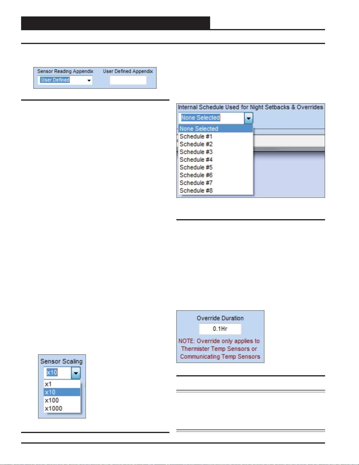
Sensor Reading Appendix
Figure 12: Sensor Reading Appendix Field
Select from the drop down list in the <Sensor Reading Appen-
fi eld (Figure 12 below) to give the sensor reading a qualifi er.
dix>
For User Defi ned, type in your own qualifi er in the < User Defi ned
Appendix>
fi eld.
User Defi ned: Enter your own in the
●
User Defi ned Appendix fi eld
°F: Fahrenheit
●
°C: Celsius
●
PPM: Parts Per Million
●
PSI: Pound per Square Inch
●
“WG: Inches of Water Gauge
●
Ft.: Feet
●
RPM: Revolutions per Minute
●
Internal Schedule Used for Night Setbacks
and Overrides
If this input is reading a temperature sensor which will be using Night
Setbacks or Unoccupied Overrides, select the applicable schedule.
See Figure 14 below. Actual Schedules are set in the Schedules
Window. See instructions on page 35 for setting Schedules.
Figure 14: Schedule for Night Setbacks and
Overrides
RH%: Humidity Percentage
●
%: Percentage
●
VDC: Volts D.C.
●
BTU: British Thermal Unit
●
CFM: Cubic Feet per Minute
●
HR: Hours
●
MIN: Minutes
●
GPM: Gallons per Minute
●
Sensor Scaling
All readings are user-scalable according to the number of digits
to the right of the decimal point. See Figure 13 and values and
examples below.
X 1 65°F
●
● X 10 65.5°F
● X 100 65.54°F
● X 1000 65.543°F
Figure 13: Sensor Scaling Field
Override Duration
When setting an Override Duration, you must fi rst select the schedule
in the <Internal Schedule Used for Night Setbacks & Over-
rides>
Sensor or a Communicating Temperature Sensor is used, an Override Duration can be entered. When the Override Button is pushed
on one of these sensors during the scheduled Unoccupied Mode,
the schedule will be overridden back into the Occupied Mode. The
Override Duration determines the amount of time the schedule will
remain in Override Occupied Mode.
fi eld. When either a WattMaster Thermistor Temperature
Type a value between
.1 Hours and 24 Hours
and press <ENTER>
to save.
Figure 15: Override Duration Field
NOTE: If using a Thermistor Sensor, the Override can be
cancelled by pressing the override button for 3 to 10
seconds. If using a Communicating Sensor with an
Override button, pressing the button while in Override
operation will cancel the Override.
14
GPC-XP Controller Technical Guide
Page 15
Section 4: Confi guring Analog Inputs
Reading Average, Broadcast, and Scaling
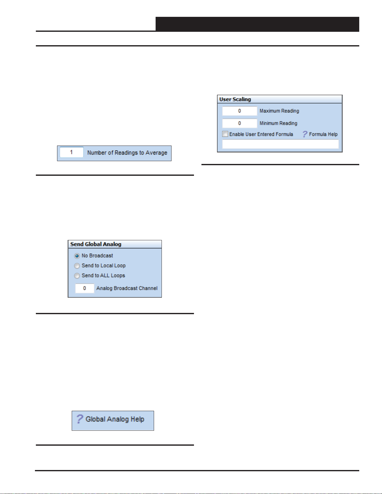
Number of Readings to Average
This function has the capability of averaging up to 25 sensor readings before it displays a new value on the GPC-XP Controller Status
Screen. Sensor values are read once per second.
Type the number of readings from this sensor you want to aver-
age in the
<ENTER> to save. See Figure 16. Valid entries are from 1-25.
If you want the input sensor to only show its most current reading,
enter <1>.
<Number of Readings to Average> fi eld and press
Figure 16: Number of Readings to Average Field
Send Global Analog
The reading of this sensor can also be “broadcast” to other controllers
on the communications loop. See Figure 17 below. The following
options are available: No Broadcast, Send to Local Loop, or Send
to ALL Loops.
User Scaling
The User Scaling Box allows you to set a Maximum and Minimum
Reading for the specifi c 4-20 mA or 0-5 vdc sensor you are using.
See Figur e 19 below. T ype in the values and press
Figure 19: User Scaling Box
User Entered Formula
The User Entered Formula fi eld allows you to create a custom math
function (formula) associated with the Analog Input of the screen
you are on. The product of this formula will then be displayed as the
value of that Analog Input, just as if it were the reading of a sensor
connected to the input. This value can then be used in the control
logic of a Relay Output or an Analog Output or it can be used in a
AVC Highest/Lowest/Average calculation.
The formula can utilize the value(s) of any of the Analog Inputs, the
Analog Outputs, the calculated AVC Highest/Lowest/Average values
of several sensors, as well as other values listed in the Formula Help
Window accessed by clicking on the question mark next to Formula
Help in the User Scaling Box.
<ENTER> to save.
Figure 17: Send Global Analog Box
If you select < Send to Local Loop> or < Send to ALL Loops>, you
must also type a channel in the
and press
for broadcast use. There are 31 available channels, but channels 1
to 14 are pre-defi ned for specifi c uses. See Figure 110, page 48 in
the Appendix for the list of predefi ned channels that appear in the
Global Analog Help Screen.
Left or right click on the Question mark beside Global Analog Help
to access information about the Global Broadcasts and to view pre-
defi ned channels. See Figure 18 below.
<ENTER> to save. You must select from channel 15 to 31
< Analog Broadcast Channel> fi eld
Figure 18: Accessing Global Analog Help
To use this function you must click the <Enable User Entered
Formula> check box and then type the formula in the text box and
press <ENTER> to save.
Left or right click on the Question mark beside Formula Help to
access information about accepted formula formats.
To view the Formula Help Screen which contains some examples,
see the Formula Help section on page 49.
A maximum of 60 characters is allowed in the formula, so refrain
from using spaces between characters and operators as they will use
up needed space for the actual formula.
If you enter a formula incorrectly or create an invalid math function,
such as dividing by zero, the Analog Input Window will display the
word ERROR for that input so that you know something needs to
be corrected in your formula.
GPC-XP Controller Technical Guide
15
Page 16
Section 4: Confi guring Analog Inputs
Alarms, Calibration, and Overrides
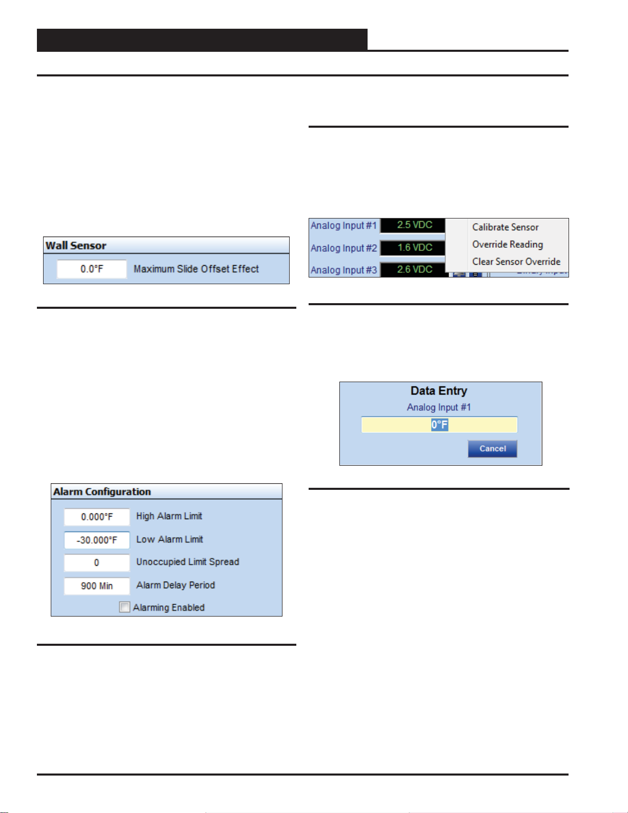
Wall Sensor
If the sensor has been confi gured as a Wall Sensor Slide Offset,
and you are using a WattMaster OE212, OE213, or Digital Space
Temperature Sensor with the slide offset function, type the amount
of the desired offset in < Maximum Slide Offset Effect> fi eld and
press <ENTER> to save. See Figure 20 below.
The value you enter is the amount of offset that will be applied to
the Space Temperature Setpoint when the slider is all the way up or
all the way down. At the center slide position, the Offset will have
no effect on the current Space Temperature Setpoints.
Figure 20: Maximum Slide Offset
Alarm Confi guration
High and Low Alarm Limits can be programmed if the job-site
requires out of range values to notify service personnel. The alarm
limits can be increased at night by the amount of the Unoccupied
Limit Spread. The Alarm Delay Period is the amount of time the
sensor must be outside the limits before an alarm is generated. This
prevents false alarms if the reading temporally exceeds the limit
but then recovers and stays within the limits the remainder of the
time. Type in a value and press <ENTER>. In order for the alarms
to function, the <Alarming Enabled> check box must be checked.
See Figure 21 below.
Calibrate, Override, and Clear Sensor
Override
Once confi gured, all thermistor sensors can be calibrated and all
readings can be overridden to specifi c values.
Right-click in the data entry fi eld in the Analog Inputs Window to
open the Calibrate, Override, and Clear Sensor Override Pop-Up
Menu shown in Figure 22 below and select the desired function.
Figure 22: Calibrate and Override Sensor
If you select Calibrate Sensor or Override Reading, the data entry
window as shown by Figure 23 below will open. Left-click in the yel-
low text fi eld, type in the desired value, and press
Figure 23: Data Entry Field
<ENTER> to save.
Figure 21: Alarm Confi guration
16
● Calibrate Sensor: Type a positive or negative offset that
will be applied to the current reading and press <ENTER>
to save.
●
Override Reading: Type a value that will override the
actual sensor reading and press <ENTER> to save.
Clear Sensor Override: Select to clear a sensor override
●
that was entered.
GPC-XP Controller Technical Guide
Page 17
Section 5: Confi guring Binary Inputs
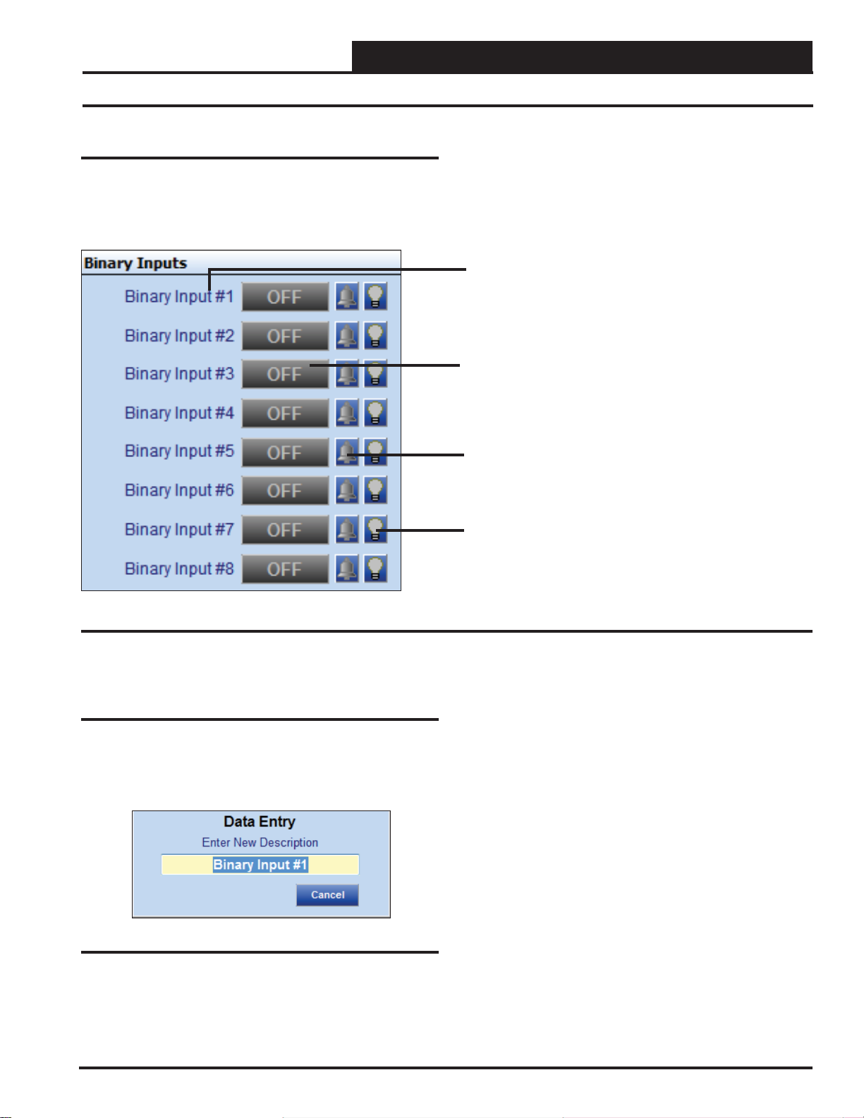
Binary Inputs
The Binary Inputs Window is located in the upper center of the
GPC-XP Controller Status Screen (Figure 8, page 11). There are 8
Binary Inputs. See Figure 24 below for the Binary Inputs Window
component details.
Components and Navigation
Right or Left-click on any of the Binary Input name
fi elds to access the description entry box to add or
change the name of the Binary Input.
Left-click on the Status box to confi gure the Binary
Input.
Right-click to override the Binary Input.
The bell will light up to indicate that an alarm is on.
The Light bulb will light up when the Input is in the
Occupied Mode.
Figure 24: Binary Input Window Components and Navigation
Renaming Binary Inputs
To give the Binary Input a new name, click on the blue highlighted
Binary Input # fi eld and the Binary Input Data Entry Dialog Box will
open (Figure 25 below). Once you have typed in a new description
(max 17 characters), press
<ENTER> to save.
Figure 25: Binary Input Data Entry Dialog Box
GPC-XP Controller Technical Guide
17
Page 18
Section 5: Confi guring Binary Inputs
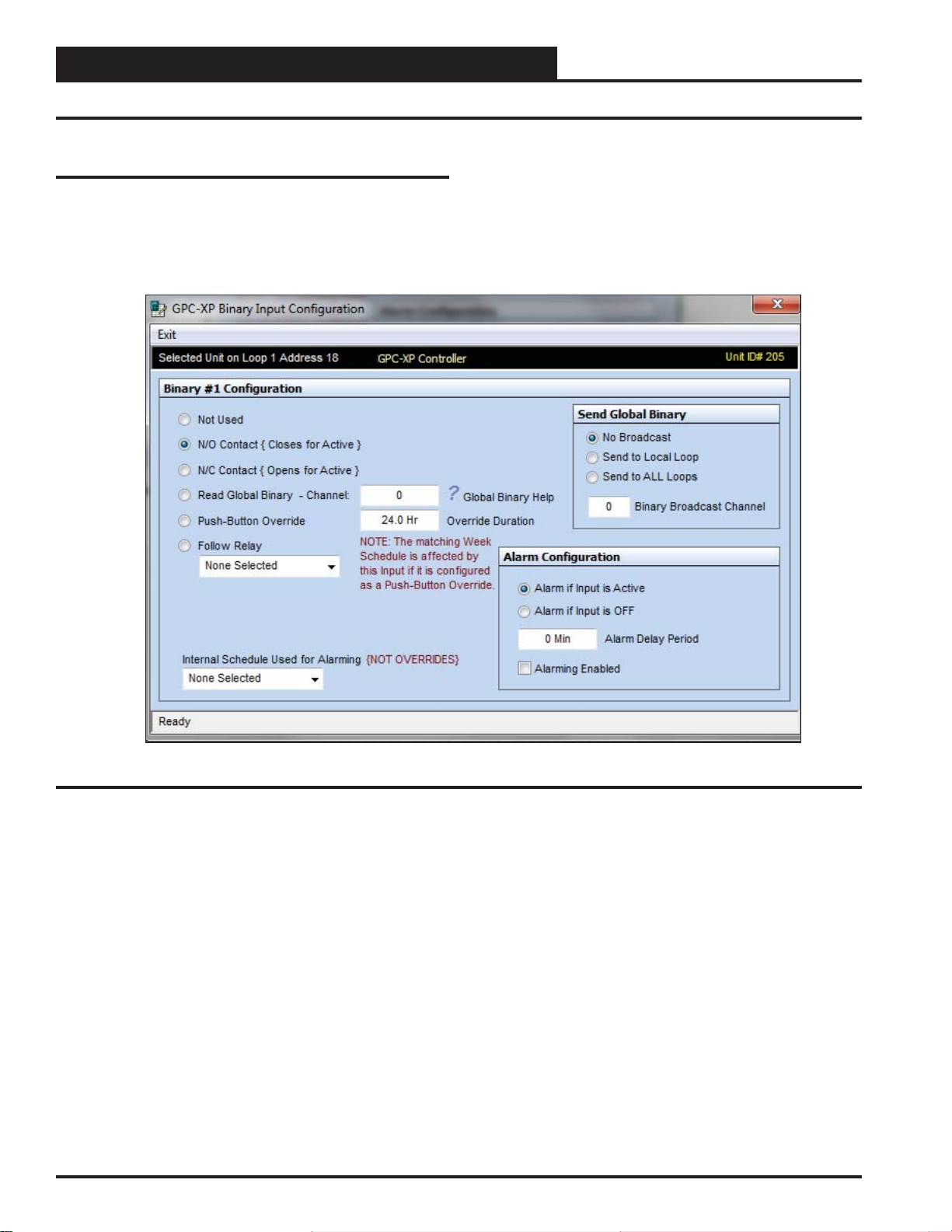
Binary Input Type
Confi guring Binary Inputs
Left-click on the “ON” or “OFF” button to the right of Binary Input
#1 in the Binary Input Window (Figure 24, page 17) to open the
Binary Input Confi guration Window (Figure 26 below). Each Binary
Input is separately confi gured, so 8 binary input combinations are
possible in one controller.
Figure 26: Binary Input Confi guration Window
Binary Confi guration
The following confi gurations are available for each Binary Input:
Not Used
●
N/O Contact (Close for Active) - This normally open
●
(N/O) input will become active when 24 VAC is applied.
N/C Contact (Open for Active) - This normally closed
●
(N/C) input will become active when 24 VAC is removed.
18
Read Global Binary - This input will read the Global
●
Binary on the selected channel. Click on the Question Mark
symbol for Help information. See Figure 111, page 48 in
the Appendix for the Global Binary Help Screen.
Push-Button Override - If a discrete Push-Button
●
Override switch (not on a space sensor) is wired to this
input, also select the Override Duration desired (up to
24 hours). An Override on Binary Input #1 would affect
Schedule #1. An Override on Binary Input #2 would affect
Schedule #2, etc.
Follow Relay - This input will be active when the selected
●
relay is ON.
GPC-XP Controller Technical Guide
Page 19

Section 5: Confi guring Binary Inputs
Send Global Binary, Alarm Confi guration & Internal Schedule
Send Global Binary
The binary condition of this input can also be “broadcast” to other
GPC-XP Controllers on the communications loop. See Figure 27
below. The following options are available: No Broadcast, Send to
Local Loop, and Send to ALL Loops.
Figure 27: Send Global Binary Box
If you select < Send to Local Loop> or < Send to ALL Loops>,
you must also type a channel in the < Binary Broadcast Channel>
fi eld and press <ENTER> to save. There are 16 available binary
channels you can use.
Left or right click on the Question mark beside Global Binary Help
to access information about the Global Broadcasts. See Figure 28
below. See Figure 1 11, page 48 in the Appendix for Global Binary
Help.
Internal Schedule Used for Alarming
(Not Overrides)
The confi gured Alarm condition will only become active during the
Occupied Period of the selected schedule. See Figure 30 below.
Actual Schedules are set in the Schedules Window. See instructions
on page 35 for setting Schedules.
Figure 30: Internal Schedule Used for Alarms
Override
Once configured, Binary Inputs can be overridden to specific
conditions.
Figure 28: Accessing Global Binary Help
Alarm Confi guration
You can select an alarm designation for this input based on if the
input is active (ON) or input is OFF. The Alarm Delay Period is the
time that must elapse after the ON/OFF condition occurs before
the Alarm occurs. The maximum delay period is 300 minutes. The
< Alarming Enabled> box must be checked for Alarming to occur.
See Figure 29 below.
Figure 29: Alarm Confi guration
Right-click on the Status box in the Binary Inputs Window (Figure
24, page 17) to open the Override Binary Menu shown in Figure
31 below, and select the desired function.
Figure 31: Override Binary Input
●
AUTO: Select to have a Binary Input turn ON and OFF on
its own.
ON: Select to override and turn a Binary Input ON.
●
OFF: Select to override and turn a Binary Input OFF.
●
GPC-XP Controller Technical Guide
19
Page 20

Section 6: Confi guring Relays
Components and Navigation
Relays
The Relays Window is located in the upper right of the GPC-XP
Controller Status Screen (Figure 8, page 11). There are 8 Relays.
See Figure 32 below for the Relays Window component summary
and the pages that follow for details.
Right or left-click on any of the Relay fi elds
to access the description entry box to add or
change the name of the Relay.
Left-click on this Status box to confi gure the
Relays.
Right-click to override the Relay.
The bell will light up to indicate that an alarm
is on.
The Light bulb will light up when the Input is in
the Occupied Mode.
Figure 32: Relays Window
Renaming Relays
To give the Relay a new name, click on the blue highlighted Relay
# fi eld and the Relay Data Entry Dialog Box will open (Figure 33
below). Once you have typed in a new description, press
to save.
<ENTER>
Hi Limit Setpoint and Lo Limit Setpoint.
Amount of time in hours and minutes that the
relay has been energized.
Figure 33: Relay Data Entry Dialog Box
20
GPC-XP Controller Technical Guide
Page 21

Section 6: Confi guring Relays
Confi guring Relays
Left-click on the “ON” or “OFF” button to the right of the Relay # in
the Relays W indow to open the Relay Confi guration Screen. (Figure
34 below). There are (8) relay confi gurations available.
The Relay Confi guration Screen contains (5) windows which are
described on the pages that follow:
●
Main Control Method
● Logical AND Control Method
● Logical OR Control Method
● Timing & Alarming
● Relay Output Type
Relay Confi guration Window
Figure 34: Relay Confi guration Screen
GPC-XP Controller Technical Guide
21
Page 22

Section 6: Confi guring Relays
Main Control Method Window
Main Control Method
The Main Control Method Window (Figure 35 below) is located
on the left of the Relay Confi guration Screen (Figure 34, page 21).
Figures 36 through 43 will walk you through the confi guration steps
in this window. As you select items, the corresponding fi elds that
you need to fi ll out will become available. Fields that do not pertain
to the confi guration at hand will be greyed out.
Control Method Field
Figure 36: Control Method Field
● Not Confi gured – Select this if this relay will not be used.
Above/Below Options – These options work with the Hi
●
Limit and Lo Limit Setpoints. See Figure 35.
• On Above / Off Below • On Above / On Below
• Off Above / On Below • Off Above / On Below
Figure 35: Main Control Method Window
● Follow Active/Inactive Binary Input Options – If one
of these options is selected, you must then go to the Binary
Input to Follow fi eld (see Figure 44, page 25)—and select
which Binary Input this Relay Output will be associated
with. If the Follow Active Binary Input is selected, this relay
will energize when the selected Binary Input is Active. If
the Follow Inactive Binary Input is selected, this relay will
energize when the selected Binary Input is Inactive. For
example, if the Main Control Method is “Follow Active
Binary Input” and the Binary Input chosen is confi gured
“N/O Contact (Closes for Active)”, then this relay will
be energized when 24 VAC is applied to the binary input
and the N/O contact closes (Active). If the Binary Input
chosen is “N/C (Opens for Active)”, then this relay will be
energized when 24 VAC is removed from the binary input
and the N/C contact opens (Active).
• Follow Active Binary Input • Follow Inactive Binary Input
● Follow Relay Output – If this option is selected, you must
then go to the Relay to Follow fi eld (Figure 45, page 25)
and select another relay that this relay is to follow. For
example, if you are confi guring Relay #1, you can confi gure
it to energize whenever Relay #2 (based on its logic)
energizes.
22
GPC-XP Controller Technical Guide
Page 23

Section 6: Confi guring Relays
Main Control Method Window
● Follow Schedule – If this option is selected, you must
then go to the Controlling Schedule fi eld (Figure 43,
page 25)—and select the desired Schedule. This relay
will be energized whenever the selected Schedule is in the
Occupied Mode. See the Setting Schedule Section on page
35 on how to set up Schedules. (This option is not available
with Logical AND/OR operations. See page 26.)
Ventilation Control – If this option is selected, you must
●
then go to “Ventilation Control” at the bottom right of the
Relay Confi guration Screen (Figure 34, page 21). There
you can confi gure a “Vent Mode ON Time” and a “Vent
Mode OFF Time.” This relay will then energize for the
duration of the confi gured “Vent Mode ON Time” and
then will de-energize for the duration of the confi gured
“Vent Mode OFF Time.” You have the option of selecting
a Controlling Schedule for this function to follow. If no
Schedule is confi gured, this relay will cycle continuously
for the Vent Mode On/Vent Mode Off operation. If a
Schedule is confi gured, the Vent Mode On/Off will only
cycle the relay during the scheduled Occupied hours. See
the Ventilation Control description on page 27. (This option
is not available with Logical AND/OR operations. See page
26.)
Lead Relay for Lead/Lag Control – If this option is
●
selected, you can also select a Control Source input in
the next fi eld to be used as a Proof of Operation to allow
switching to the Lag Relay upon a failure. This proof can
either be a binary contact activation or an analog input
level. If your Proof is an analog input level, you can then
confi gure either an Increasing or Decreasing Proof Setpoint
(Figure 39, page 24).
If your Proof is a Binary Input, the Proof Failure is initiated
when the selected Binary Input is “Active” (See Confi guring
Binary Inputs on page 18.)
In the Timing and Alarm Section (Figure 34, page 21) at the
right of the Relay Confi guration Screen (Figure 34, page
21), you can confi gure a Lead/Lag Changeover Interval and
a Proof Failure Timeout Delay. For further information, see
the Lead/Lag description on page 27. (This option is not
available with Logical AND/OR operations. See page 26.)
Control Source Field
Figure 37: Control Source Field
A Control Source needs to be selected anytime you select one of the
Above/Below Control Methods. A Control Source also needs to be
selected anytime you select “Lead Relay for Lead/Lag Control” and
you need a Proof Source to switch to Lag based on a failure condition. If you selected any other option as a Control Method, then the
Control Source fi eld is not applicable and will not be available to
make a selection.
When a Control Source is selected, in most cases you will then need
to confi gure Control Source Setpoints – either as Hi/Lo Setpoints or
as Increasing/Decreasing Proof Setpoints. See the Control Source
Setpoints fi eld (Figure 38 & 39, page 24). In some cases, a Binary
Input could be selected as the Control Source (acting as the Proof
Source) for Lead/Lag changeover. For example, a Binary Input
could monitor a Proof of Flow (POF) Switch. When the POF switch
is closed and the Binary Input is Active, the Lead Relay would be
energized. If the POF Switch opens and the Binary Input becomes
Inactive, the controller would switch to the Lag relay. In this case
the Control Source Setpoints would not be used.
The Control Source Options are shown below:
●
Analog Inputs # 1-8
Lag Relay for Lead/Lag Control – This Lag Relay will
●
follow the same confi gurations as the Lead Relay.
Active on ANY Alarm (Not shown in Figure 36)– There
●
are several Alarm Confi guration options available on the
GPC-XP. If any of these alarm conditions occur, this relay
will energize.
GPC-XP Controller Technical Guide
● Outdoor Air Temp Broadcast
● OA Wetbulb
● OA Dewpoint
● AVC Highest Reading
● AVC Lowest Reading
● AVC Average Reading
● Binary Inputs #1- 8 (Not shown in Figure 37)
● Analog Outputs #1- 4 (Not shown in Figure 37)
23
Page 24

Section 6: Confi guring Relays
Main Control Method Window
Control Source Setpoints
If the Control Method for this Relay is one of the Above/Below
options, then the Control Source Setpoints need to be confi gured.
See Figure 38 below.
The “High Limit Setpoint” and the “Low Limit Setpoint” establish
the Control Window.
For example, if “On Above/Off Below” is selected as the Control
Method, then the relay will energize above the High Limit Setpoint
and will de-energize below the Low Limit Setpoint. In between is
a deadband.
If “On Above/On Below” is selected as the Control Method, then
the relay will energize above the High Limit Setpoint and below
the Low Limit Setpoint. In between these setpoints, the relay will
be de-energized.
The “ Night Setback Setpoint Spread” is the offset to the High and
Low Limit Setpoints used during the Unoccupied Mode. The Question Mark feature is not used in this case.
Slide Offset Channel Field
If you are using a WattMaster standard OE212 or OE213 Flush Mount
Wall Sensor which has the optional slide offset switch, and you want
that slide switch to adjust the Control Source Setpoints up or down,
be sure to select the analog input the slide offset was connected to
(Control Source fi eld, Figure 37, page 23). See Figure 40 below.
If you are using a Digital Communicating Temperature sensor
(OE217-00) and it is the Control Source, its slide offset will automatically be used if Control Source Setpoints were entered. In this
case, you do not need to confi gure the Slide Offset Channel.
The slide offset effect will be refl ected on the Main GPC-XP Status
Screen in the Setpoints fi eld next to this relay (Figure 8, page 11).
The Hi Limit and Lo Limit Setpoints on this current screen will
always refl ect their confi gured values.
Figure 38: Control Source Setpoints
If the Control Method for this Relay is Lead Relay for Lead/Lag
Control, then the Setpoint fi eld in Figure 39 below will appear:
Figure 39: Control Source Setpoints for Lead Relay
for Lead / Lag Control
The “Increasing Proof Setpoint” would be used if the Control Source
input needs to rise to a certain level to establish Proof of Operation.
The “Decreasing Proof Setpoint” would be used if the Control
Source input needs to fall below a certain level to establish Proof of
Operation. Clicking on the Question Mark will show Help information. Do not enter a value for both setpoints or the Increasing Proof
Method will take control. If the Lead/Lag Proof is a binary input,
these setpoints are not used. The Night Setback Setpoint Spread fi eld
is not available in this confi guration.
Figure 40: Slide Offset Channel
Reset Source/Reset Source Limits Field
You can select an input as the Reset Source (that is, any Source except
the Binary Inputs) that will cause your Control Source Setpoint to be
proportionally reset between the Lo Limit Setpoint and the Hi Limit
Setpoint as the Reset Source changes from its programmed Minimum
Limit to its Maximum Limit. The reset can be made reverse acting
by reversing the Min/Max reset limits so that the Min is the higher
value. See Figures 41 & 42.
24
Figure 41: Reset Source
GPC-XP Controller Technical Guide
Page 25

Section 6: Confi guring Relays
Figure 42: Reset Source Limits
Controlling Schedule Field
You can select one of the Internal Schedules to set the occupied or
unoccupied mode of operation for this selected relay. If the relay
does not require a schedule to be part of its control strategy, leave
the selection as “None Selected.” This will cause the controller to
assume it is always “occupied” and therefore always available for
operation. See Figure 43 below.
Main Control Method Window
Relay to Follow Field
If you want this relay to energize at the same time as another relay
(based on that relay’s control logic), select “Follow Relay Output”
in the Control Method fi eld, Figure 36, page 22) and select the
other relay here (Figure 45 below).
Figure 45: Relay to Follow
Figure 43: Controlling Schedule
Binary Input to Follow Field
You can confi gure this relay to energize whenever a selected Binary
Input is Active/Inactive. If the Control Method you confi gured for
this relay is “Follow Active/Inactive Binary Input” (see Figure 36,
page 22 for more detail), you need to select which Binary Input
will cause this relay to energize in the appropriate condition. See
Figure 44 below. The Binary Input does not require a physical
contact closure to become active. It can follow a global broadcast or
some other event as noted in the Binary Input Confi guration section
(pages 18 & 19).
Enabling Relay Field
When confi guring the operation of a relay, an Enabling Relay can
also be selected. The operation of the confi gured relay can only occur
once the Enabling Relay (based on its logic) has energized. For example, a Cool Stage Relay could be prevented from energizing until
a Fan Relay (Enabling Relay) has fi rst energized (Figure 46 below).
Figure 46: Enabling Relay
Figure 44: Binary Input to Follow
GPC-XP Controller Technical Guide
25
Page 26

Section 6: Confi guring Relays
Logical AND Control Method & Logical OR Control Method
Logical AND Control Method & Logical OR
Control Method
If more than one criterion is required to make a decision to energize
a relay, there are two other options available to use in the decision
process— a “Logical AND” condition and a “Logical OR” condition. If you do not need any additional criterion, simply select the
<Not Confi gured> option under the Control Method for each of
these sources.
If you need two events to be true before the relay output can be
activated, use the Main Control Method in conjunction with the
Logical AND Control Method. If you want either one event or a
second event to activate this relay, use the Main Control Method in
conjunction with the Logical OR Control Method.
You can combine all three options to create a condition where two
events must be true (2 AND Statements) or a 3rd separate event (OR
Statement) must be true to activate this relay.
Confi guration of the Logical And Control Method and the Logi-
cal OR Control Method is similar to the confi guration of the Main
Control Method.
Figure 48: Logical OR Control Method Window
The Logical AND Control Method Window and the Logical OR
Control Method Window are located in the center of the Relay
Confi guration Screen (Figure 34, page 21). See Figures 47 & 48.
Figure 47: Logical AND Control Method Window
26
GPC-XP Controller Technical Guide
Page 27

Section 6: Confi guring Relays
Timing & Alarming & Relay Output Type
Timing & Alarming
The T iming & Alarming W indow (Figure 49 below) is located on the
right of the Relay Confi guration Screen (Figure 34, page 21). The
corresponding fi elds that you need to fi ll out will become available
based on your previous selections.
Lead/Lag Control
If you have confi gured this relay for “Lead Relay for Lead/Lag
Control,” you will also need to set the “Changeover Interval” and
the “Proof Failure Timeout Delay.”
The Changeover Interval is used to toggle the Lag output into the
Lead output once the runtime hours of the Lead output exceed this
amount of time on the Lag output.
The Proof Failure Time Out Delay is the amount of time given for the
“Proof Source” input to become active once the Lead or Lag output
is energized. If this proof is not made within the specifi ed amount
of time, the controller switches to the Lag output in an attempt to
get the controller running and then sets an alarm to fl ag the user that
a failure has occurred. See Lead /Lag information on pages 22-24
for more detail.
Ventilation Control
If you confi gured the relay for “Ventilation Control,” you can set
the “ Vent Mode ON Time” and the “ Vent Mode OFF Time.” This
means that the output is active for the Vent Mode ON Time and then
cycles off for the Vent Mode OFF Time. If the output is not enabled
by a schedule, it will continue to cycle indefi nitely at the On/Off
rate. See additional information on page 23.
Figure 49: Timing & Alarming Window
Delay & Run Times
Once activated, the Relay can be forced to remain “On” for the
“ Minimum Run Time.” Once de-activated, the Relay can be forced
to remain “Off” for the “ Minimum Off Time.” The “ Starting Delay
Period” is the period of time before the Relay is called to activate
and the time it is actually energized.
Run Time Alarming
If the selected relay output is controlling a device that needs periodic maintenance, you can enter a “ Run Time Alarm Delay Period”
that once exceeded generates an alarm. If you need to protect the
equipment, you can select the Disable Relay box, and the relay will
de-activate once this run time has been exceeded. To reset the Run
Time Alarm, you must cycle power or uncheck the Disable Relay
box and then re-check the box.
Relay Output Type
The Relay Output Type Window (Figure 50 below) is located on
the far bottom right of the Relay Confi guration Screen (Figure 34,
page 21). Normally when the relay is On, the output is active. If
you want to reverse that operation and have the output active when
the relay is Off, select the second option.
Figure 50: Relay Output Type Window
GPC-XP Controller Technical Guide
27
Page 28

Section 7: Confi guring Analog Outputs
Components and Navigation
Analog Outputs
The Analog Outputs W indow is located in the lower right-hand side
of the GPC-XP Controller Status Scr een (Figure 8, page 11). There
are 4 Analog Outputs. See Figur e 51 below for the Analog Outputs
Window component summary. See the pages that follow for details.
Enabled or Disabled indicates whether the output is active
or inactive.
Right or Left-click on any of the Analog Output
name fi elds to access the description entry box
and change the name of the Analog Output.
Left-Click in the data entry fi eld to confi gure the
Analog Output.
Right-Click on these fi elds to access the
Override and Cancel Override options.
The Light bulb will light up when the Output is in the
Occupied Mode.
Current Analog Output Setpoint
Figure 51: Analog Outputs Window Components and Navigation
Renaming Analog Outputs
To give the Analog Output a new name, click on the blue highlighted
Analog Output # fi eld and the Analog Output Data Entry Dialog
Box will open (Figure 52 below). Once you have typed in a new
description, press <ENTER> to save.
Figure 52: Analog Output Data Entry Dialog Box
28
GPC-XP Controller Technical Guide
Page 29

Section 7: Confi guring Analog Outputs
Analog Output Confi guration Window
Confi guring Analog Outputs
Left-click in the data entry fi eld in the Analog Outputs W indow (Fig-
ure 51, page 28) to open the Analog Output Confi guration Window
(Figure 53 below).
Figure 53: Analog Output Confi guration Window
Control Type Field
The following are the control options available (Figure 54 below):
Figure 54: Control Type Field
GPC-XP Controller Technical Guide
Not Confi gured
●
● Direct Acting Floating Point
● Reverse Acting Floating Point
● Direct Acting PID
● Reverse Acting PID
29
Page 30

Section 7: Confi guring Analog Outputs
Control Type
Floating Point Control
Floating Point Control works best on slow changing applications
where the amount of time it would take to drive full on or full off
is not as critical. For faster response, the PID Control method is
recommended.
With Direct Acting Floating Point Control, as the selected Control
Source rises above Setpoint, the Analog Output voltage signal increases to try to maintain the Setpoint. As the Control Source falls
below Setpoint, the Analog Output voltage signal decreases.
With Reverse Acting Floating Point Control, as the selected Control
Source rises above Setpoint, the Analog Output voltage signal decreases to try to maintain the Setpoint. As the Control Source falls
below Setpoint, the Analog Output voltage signal increases.
A Deadband above and below the Setpoint can be confi gured in
which no control signal change is made.
With Floating Point Control, you can confi gure a Calculation Interval
and a Proportional Control Window. See Figure 55 below.
Figure 55: Calculation Settings for Floating Point
Control
Calculation Interval - Determines how often the control signal
calculation is made to try to reach setpoint. Setting this too fast can
cause over-shooting.
Proportional Control Window - Determines how large of a sig-
nal change will occur at each Calculation Interval. The larger the
Proportional Window, the smaller the signal change will be at each
Calculation Interval.
PID Control
PID Control allows Proportional, Integral, and Derivative Rate of
Change Control. With this option, you can confi gure the Proportional
Control Window, an Integral Constant, and a Derivative Constant
as well as the Calculation Interval and PID Derivative Filter. See
Figure 56.
With Direct Acting PID Control, as the selected Control Source rises
above Setpoint, the Analog Output voltage signal increases to try to
maintain the Setpoint. As the Control Source falls below Setpoint,
the Analog Output voltage signal decreases.
With Reverse Acting PID Control, as the selected Control Source
rises above Setpoint, the Analog Output voltage signal decreases
to try to maintain the Setpoint. As the Control Source falls below
Setpoint, the Analog Output voltage signal increases.
Figure 56: Calculation Settings for PID Control
Calculation Interval - Determines how often the control signal
calculation is made to try to reach setpoint. Setting this too fast can
cause over-shooting.
Proportional Control Window - Determines how large of a sig-
nal change will occur at each Calculation Interval. The larger the
Proportional Window, the smaller the signal change will be at each
Calculation Interval.
Integral Constant - Accelerates the movement of the process
towards setpoint and eliminates the residual steady-state error that
occurs with a pure proportional controller. However, since the integral term responds to accumulated errors from the past, it can cause
the present value to overshoot the setpoint value. We recommend to
start with a small Ki and increase it until a small overshoot occurs
and then dial it back.
Derivative Constant - The derivative term slows the rate of change
of the controller output. Derivative control is used to reduce the
magnitude of the overshoot produced by the integral component
and improve the combined controller-process stability. However,
the derivative term slows the transient response of the controller.
Also, differentiation of a signal amplifi es noise and thus this term in
the controller is highly sensitive to noise in the error term, and can
cause a process to become unstable if the noise and the derivative
gain are suffi ciently large. We recommend to start with a small Kd
and increase it until overshoot is reduced to desired point.
PID Derivative Filter - The controller will average this number of
input changes in order to smooth out a fast changing value.
If the Derivative Constant (Kd) is set to “0,” then control will be
the Proportional/Integral (PI). If both the Derivative Constant (Kd)
and the Integral Constant (Ki) are set to “0,” then the control will
only be Proportional.
30
GPC-XP Controller Technical Guide
Page 31

Section 7: Confi guring Analog Outputs
Control Source, Control Setpoints, Setpoint Reset Source
Control Source
The Control Source Options are as follows (Figure 57 below):
●
Analog Inputs #1 - 8
● Outdoor Air
● OA Wetbulb
● OA Dewpoint
● AVC Highest Reading
● AVC Lowest Reading
● A VC A verage Reading
● Analog Outputs #1-4 (not shown in
Figure 57)
Setpoint Reset Source
You can confi gure a Setpoint Reset Source that will allow reset of
the Control Setpoints (Figure 59 below). Once a Reset Source is
selected, you will be able to confi gure both a “Max Setpoint” and a
“Min Setpoint” as well as a Max Reset value and a Min Reset value
(Figure 58). As the Reset Source value varies between the Max and
Min Reset values, the Control Setpoint will be proportionally reset
between the Max and Min Control Setpoints. At the Max Reset
value, the Control Source will be at the Max Setpoint, regardless if
it is an inverse relationship.
Figure 57: Control Source
Control Setpoints & Reset Limits
For most applications, only the Max Setpoint and the Deadband will
be used. See Figure 58 below. Unless a Setpoint Reset Source is
selected, the other values in this section will be grayed-out and not
used. In this situation, the Max Setpoint will be the setpoint you are
trying to maintain. The Deadband is the range above and below the
Setpoint in which no control signal change is made.
Figure 58: Control Setpoints & Reset Limits
Figure 59: Setpoint Reset Source
Disabled Mode Offsets
The Disabled Mode Offsets (Figure 60 below) can be used if you
are using an Enabling Relay, an Enabling Binary Input, or a Controlling Schedule. Anytime this output is not enabled by the Enabling
Relay or the Enabling Binary, or is in the Unoccupied Mode (per the
Schedule), these offsets will be applied to the Max/Min Setpoints
to initiate the control operation of this analog output. These would
then act as “Night Setback” type offsets. If these offset values are
‘0’, there will be no Disabled Mode operation.
Figure 60: Disabled Mode Offsets
GPC-XP Controller Technical Guide
31
Page 32

Section 7: Confi guring Analog Outputs
Outdoor Air Enable, Controlling Schedule, Enabling Relay
Outdoor Air Enable
If this option is used, the Outdoor Air Temperature must be between
these setpoints for this Analog Output to function. See Figure 61
below.
Figure 61: Outdoor Air Enable Setpoints
Controlling Schedule
No matter what Control Method or Control Source has been selected,
each analog output can be confi gured to follow a schedule. See Fig-
ure 62 below. Actual Schedules are set in the Schedules Window.
See instructions on page 35 for setting Schedules.
Enabling Binary Input
An Enabling Binary Input can also be selected (Figure 64 below).
The operation of this Analog Output will only occur once the selected
Binary Input is Active.
For example, if the Binary Input selected is confi gured as “N/O Con-
tact (Closes for Active),” then this Analog Output is enabled when
24 VAC is applied and the N/O Binary Input contact closes (Active).
If the Binary Input selected is confi gured as “N/C (Opens for Ac-
tive),” then this Analog Output will be enabled when 24 VAC is
removed and the N/C Binary Input contact opens (Active).
Figure 62: Controlling Schedule
Enabling Relay
An Enabling Relay can also be selected. The operation of this Analog
Output will only occur once the Enabling Relay (based on its logic)
has energized. See Figure 63 below.
Figure 63: Enabling Relay
Figure 64: Enabling Relay Binary Input
Output Voltage Limits
This output normally operates with a range of 0-10 VDC. If you need
it to operate with a different Min and/or Max voltage, those voltages
can be entered in the Output Voltage Limits Box (Figure 65 below).
Figure 65: Output Voltage Limits
32
GPC-XP Controller Technical Guide
Page 33

Section 7: Confi guring Analog Outputs
Alternate Override and Override
Alternate Override
An Alternate Override Source can be selected to override the output
signal of this Analog Output to a fi xed value when a certain condition
occurs (Figure 66 below).
Finally, select the voltage you want to hold this output to based on
the above logic (Figure 68 below).
Figure 68: Voltage
Override & Cancel Override
You can manually override the logic of an Analog Output and force
it to a specifi c voltage. The Override Voltage fi eld defaults to “-1.0”
which means no override.
Right-click in the data entry fi eld in the Analog Outputs Window
(Figure 51, page 28) to open the Override Voltage Box shown in
Figure 69 below and enter an override value. Click the <Enter>
button to save the value. If you enter an incorrect value, click the
<Clear> button to start over. If there is any value in the fi eld, in-
cluding “0” when you click <Enter>, the voltage from this output
will be forced to that value. Canceling the Override will cause the
voltage to go back to its original reading, and the Override Voltage
fi eld will display “-1.0”.
Figure 66: Alternate Override
First select which Override Source to use:
●
Analog Inputs # 1 – 8
● Outdoor Air
● OA Wetbulb
● OA Dewpoint
● AVC Highest Reading
● AVC Lowest Reading
● A VC A verage Reading
Next select the logic, setpoint, and deadband that will determine the
Override (Figure 67 below). Right or left-click in the Logic Field
to select < , >, or =.
Figure 67: Logic, Setpoint, and Deadband
Figure 69: Calibrate and Override Sensor
GPC-XP Controller Technical Guide
33
Page 34

Section 8: Outdoor Status & AVC Status
Outdoor Status and AVC Status Windows
Outdoor Status
The Outdoor Status Window is located in the center of the GPC-
XP Controller Status Screen (Figure 8, page 11) and displays the
Outdoor Air (OA) Temperature, the OA Humidity, the OA Wetbulb,
and OA Dewpoint. See Figure 70 below.
Figure 70: Outdoor Status Window
If the OA Temperature and OA Humidity values are available, the
GPC-XP will always calculate the OA Wetbulb and the OA Dewpoint
values shown in this section. The values can be selected as Control
Source options when confi guring Relay Outputs and Analog Outputs.
To select which Analog Inputs will be used for this AVC operation,
click
<Setpoints> from the Toolbar located at the top of the GPC-
XP Status Screen. Then click <Miscellaneous Settings>. The
Miscellaneous Settings Screen will open. See Figure 85, page 40.
In the AVC Inputs Window, select the Analog Inputs that you wish
to include in the AVC function. See Figure 72 below. Inputs not
selected will perform their normal confi gured function and will not
affect the AVC operations.
For details on setting up the OA Temperature and OA Humidity
sources, as well as other related information, see the Outdoor Air
Broadcast section on the Miscellaneous Setpoints Screen on page 42.
AVC Status
The AVC (Analog Value Comparison) Status Window is located in
the center of the GPC-XP Controller Status Scr een (Figure 8, page
11). The GPC-XP has the capability to select the current Highest or
Lowest Reading or to calculate the current Average Reading from
selected Analog Inputs. These values appear in the AVC Status
Window. See Figure 71 below.
Figure 71: AVC Status Window
Figure 72: AVC Inputs Window
NOTE: Limits can be set for a Rogue Sensor, so that it is not
included in the AVC Average function. See Rogue
Sensor Limits section, page 42.
34
GPC-XP Controller Technical Guide
Page 35

Section 9: Setting Schedules
Schedules Window Components and Navigation
Schedule Status Window
The Schedule Status Window is located in the bottom left of the
GPC-XP Controller Status Screen (Figure 8, page 11) and allows
(8) Schedules and (8) associated Holiday Schedules, Overrides, and
Force Mode. See Figure 73 below for the Schedule Status Window
components and summary and the pages that follow for details.
Click to open
Schedules Window
Click to open
Holiday Window
Click to open
Force Window
If this Schedule is associated with a Spacer Sensor
with an Override Button (confi gured in the Analog Input
Confi guration Screen) or a discrete Pushbutton
Override Button (confi gured in the Binary Input
Confi guration Screen), this symbol will light up if the
Override Button has been pushed. See the description
of the Override Duration setpoint on page 14 in the
“Confi guring Analog Inputs” section for more details.
Figure 73: Schedule Status Window
GPC-XP Controller Technical Guide
35
Page 36

Section 9: Setting Schedules
Schedules Window
Setting Schedules
Click the <Schedule> button in the Schedules Status Window
(Figure 73, page 35) to open the Schedule Confi guration Window
(Figure 74 below). You can confi gure up to (8) separate schedules
for various uses on the GPC-XP Controller. These Schedules are
(7) day, (2) event per day Schedules.
Figure 74: Schedule #1 Confi guration #1 Window
The Schedule Confi guration Window in the example shows a 7:30
AM to 5:30 PM operating schedule for Monday through Friday. The
bars on the right side of the screen give a visual indication of the
selected time periods.
When you enter a time in any fi eld, you must designate AM or PM
press <ENTER> to save.
and
NOTE: Yo u M UST press <ENTER> to have the system accept
your entr y. If you do not press
will either not display or will not change.
The holiday start and stop times will override the standard operating hours. The holidays themselves are scheduled in the
<ENTER> , the bar graph to the right
Holiday
Schedule Window described on page 38.
To eliminate a schedule from any event, simply type a zero and press
<ENTER> for the Start and Stop time for that day. The screen will
display 12:00 AM for both the Start and Stop times, indicating that
the equipment will not activate for that day.
If you want the controller to run the full 24 hours, type a zero and
press <ENTER> to set 12:00 AM for the Start time and type 11:59
PM and
hour period will remain in the occupied mode without interruption.
press <ENTER> for the Stop time. This ensures the full 24-
Select <Save> to save your schedule. Select <R estore> to restore
a previously saved schedule.
schedule to all like controllers,
to all schedules in this window for continuous operation, and select
<Erase Schedules> to completely erase the schedule appearing
in the window. See page 37 for an explanation of each of these
functions.
WARNING: <Erase Schedules> will clear ALL entered
Select <Copy to All> to copy the
select <Set 24 Hour Operation>
stop/start times, so use with caution.
36
GPC-XP Controller Technical Guide
Page 37

Section 9: Setting Schedules
Saving, Restoring & Copying Schedules
Saving Schedules
To save the weekly time schedule, click <Save>. The File Save
Window will appear (Figure 75 below). Give the fi le a name in the
“Selected File” fi eld and click <Save> or press <ENTER> to save.
Figure 76: Copy Setpoints Window
Set 24 Hour Operation
NOTE: Make sure to save any schedules you desire before
selecting this option.
Figure 75: File Save Window
A message will pop up if the schedule is saved successfully. Click
<OK> to make it disappear.
Restoring Schedules
Click <Restore> to restore any previously saved schedule from a
previously saved fi le. Click <Open>. A message will pop up if the
schedule is restored successfully.
If you try to load a schedule from one type of controller to a different
type of controller, Prism 2 will display an error message and prevent
you from making this mistake.
Click <OK> to make it disappear.
Copying Schedules
Click <Copy To All> to copy a schedule to other controllers. The
Copy Setpoints Window will appear (Figure 76).
Select a range to copy to in the Range Box or type unit number(s)
in the
Selected Units Box and then click <Send> to start the copy
process. When the copying is complete, the message
will appear in the bottom status bar of the window.
close the window.
Copy Completed
Click <Exit> to
To set all schedules for continuous operation, click
Operation>. The Schedules Window will display constant operation
for weekends and weekdays (Figure 77 below). In order to return to
the normal schedule, you will need to restore the schedule.
<Set 24 Hour
Figure 77: Set 24 Hour Schedule Operation
Erase Schedules
WARNING: <Erase Schedules> will clear ALL entered
stop/start times, so use with caution.
GPC-XP Controller Technical Guide
To erase all schedules, click <Erase Schedules>. The schedules
will be completely cleared. In order to return to a schedule, you will
need to restore the schedule.
37
Page 38

Section 9: Setting Schedules
Setting Holidays and Schedule Override
Setting Holidays
If your job-site has days during the year when you need
to override the standard operating hours to accommodate holidays or other special events, you can use this
window to select the holidays.
To access the controller’s Holiday scheduling,
button in the Schedules Status Window (Figure 73, page 35). The
Holiday Schedule Window will appear. See Figure 78 below.
click the <Holidays>
Every defi ned holiday uses the same Holiday operating schedule
programmed in the
As in the case with Week Schedules, you can select the <Erase>
button to clear all selected holidays at one time. Refer to Week
Schedules for directions on <Save>, <Restore>, and <Copy to All>.
Holidays can only be pr og rammed for the cu rrent year. You ca nnot program
holidays before the next year occurs. Holidays do not automatically
adjust for the new year, so you will need to access this screen after
the new year and make necessary adjustments to the days that fl oat,
such as Memorial Day.
Schedules Window.
Schedule Override
To override a schedule, click on the <Force Modes> button next to
the Schedule you wish to override from the Schedules Status Window
(Figure 73, page 35). See Figure 79 below.
Figure 78: Holiday Schedule Window
Click on the date to highlight it and tag it as a holiday.
Days selected as holidays are indicated with a green background
and white text.
There are 14 holiday periods available for each year. These holiday
periods can be a single day or they can span multiple days, weeks,
or even months. The key to extended holiday periods is to make sure
you select every single day, including weekends, between the start
of the holiday and the end of the holiday.
For example, if you want to schedule a summer break, you need only
schedule one holiday period to defi ne a two or three month break
from operating in the occupied mode. Of course, the equipment will
still operate with its unoccupied settings.
Figure 79: Override Schedule
Auto - Click Auto to have the schedule run under its
●
normal schedule.
ON - Click ON to override the schedule and have the
●
schedule be continuously occupied.
●
OFF - Click OFF to override the schedule and have the
schedule be continuously unoccupied.
38
GPC-XP Controller Technical Guide
Page 39

Section 10: Confi guring Alarms
Alarm Notifi cation
The GPC-XP can generate alarms for remote alarm notifi cation if
alarms have been enabled and Prism 2 is connected and running 24
hours a day. If an alarm condition occurs, the <ALARM> button in
the upper right hand corner of the GPC-XP Controller Status Scr een
will light up. See Figure 80 below. If no alarm(s) exists, the button
will be gray. See
Figure 80: ALARM Button
Figure 81 below.
Confi guring Alarms
Figure 83: GPC-XP Alarms Window
Figure 81: No Alarms Button
Individual alarms will also be indicated with a bright red alarm bell
icon in the Analog Inputs Status, Binary Inputs Status, and Relays
Status Windows. See Figure 82 below.
Alarm
Indicator
Alarm
Indicator
Alarm
Indicator
Figure 82: Analog Inputs Status, Binary Inputs
Status, and Relay Status Alarm Icon
Confi guring and Enabling Alarms
Alarms are confi gured and enabled in the Analog Inputs Confi gu-
ration Window (Figure 11, page 13), Binary Inputs Confi guration
Window (Figure 26, page 18), and Relay Confi guration Screen
(Figure 34, page 21).
Alarms are also enabled in the GPC-XP Alarms Window. To
confi gure alarms, click on the <ALARM> or <No Alar ms> button
in the upper right hand corner of the GPC-XP Controller Status
Screen (Figure 8, page 11). The GPC-XP Alarms Window will
open. See Figure 83.
Click the Enabled box beside any Alarm you wish to enable. When
that alarm condition occurs, the
corner of the Main Prism Screen will turn bright red (Figure 80,
page 39 & Figure 6, page 10). This selection will also allow that
Alarm to send out an email notifi cation if your system is set up for
that function. See the Prism 2 Technical Guide for instructions on
setting up email alarm notifi cations.
Due to the quantity of Inputs and Outputs on the GPC-XP, alarms
have been grouped into ”Sensor Input High/Low Alarm Indication”
and “Relay Run Time Alarm Indication.”
The remaining 3 alarm indicators apply strictly to Lead/Lag Relay
operations. The Proof Source Failure indicator isn’t limited to fl ow
monitoring. It applies to any type of proof of operation your Lead/
Lag requires whether it is Temperature, CFM - Airfl ow, PPM – Parts
Per Million content, etc.
If the proof source doesn’t meet the requirements in the programmed
amount of time, the system switches to the standby output and generates the proof alarm and either the Lead or Standby alarm, depending
on which relay caused the condition.
If either or both Lead/Lag Relays generate an alarm, normal operation
can be restored by clicking the
the <R eset Lead/Lag> button will restart the system using the relay
with the least amount of accumulated run time. Both do not have
to be in an alarm state for you to reset the lead/lag operation. If the
system has switched to the standby output, it can be restored to the
lead output if you want to test it again or repairs have been made
and you just want to restore normal operations.
If both outputs generate an alarm, they will not attempt to activate
again until the
to protect the equipment from possible severe damage if an output
is attempting to operate damaged equipment.
<Reset Lead/Lag> button has been clicked. This is
<ALARM> button in the upper right
< Reset Lead/Lag> button. Clicking
GPC-XP Controller Technical Guide
39
Page 40

Section 11: Miscellaneous Settings
Screen Components
Miscellaneous Settings Screen
The Miscellaneous Settings Scr een includes settings for Week Sched-
ule Broadcasts, AVC Inputs, AVC Setpoints, Rogue Sensor Limits,
Reset Rogue Sensors, Outdoor Air Broadcasts, Trend Logging, and
Daylight Savings.
From the top toolbar of the GPC-XP Controller Status Scr een (Figure
8, page 11) , click on <Setpoints> and then click <Miscellaneous>.
See Figure 84 below.
Figure 84: Setpoints Menu - Miscellaneous
Settings
The Miscellaneous Settings Scr een will open. See Figure 85 below.
Figure 85: Miscellaneous Settings Screen
40
GPC-XP Controller Technical Guide
Page 41

Section 11: Miscellaneous Settings
Week Schedule Broadcasts, AVC Setpoints, and AVC Inputs
Week Schedule Broadcasts
The Week Schedule Broadcasts Window (Figure 86 below) located
in the Miscellaneous Settings Screen (Figure 85, page 40) allows
you to broadcast the Schedules of this GPC-XP to other Unit Controllers only on the Local Loop of this GPC-XP or to All Loops of
a multiple loop system. If an option to broadcast is chosen, all (8)
Schedules of this GPC-XP are broadcast. The decision of another
controller to accept a specifi c Schedule is confi gured on the receiv-
ing controller. Schedules cannot be broadcast from one GPC-XP to
another GPC-XP.
Figure 86: Week Schedules Broadcast Window
AVC Setpoints
In the AVC (Analog Value Comparison) Setpoints Window (Figure
87 below) located in the Miscellaneous Settings Screen (Figure 85,
page 40), you can confi gure the controller to broadcast one of the
AVC values so it can be used by another controller(s), such as an
HVAC unit controller or a second GPC-XP Controller.
Select which value to broadcast and select the channel it is to be
broadcast on. You must use an unused channel between 15 and
31, since channels 1-14 are reserved for other broadcasts. (See the
Global Analog Help Screen, page 47).
You can use two GPC-XP Controllers for this AVC function to
allow the use of up to 16 Analog Inputs in the calculation. In this
case, one GPC-XP must be confi gured to broadcast its value on a
selected channel. The second GPC-XP (which will do the fi nal AVC
calculation) must be confi gured to use that same channel to receive
the broadcast from the fi rst GPC-XP. If that fi nal AVC calculation
of the second GPC-XP is to be broadcast to another controller, then
a different channel must be selected for that broadcast.
Normally the selected AVC value is only broadcast on this controller’s Local Loop. If you want the broadcast to be broadcast to all
loops on the system, check “Broadcast to ALL LOOPS.”
AVC Inputs
In the AVC (Analog Value Comparison) Inputs Window (Figure 88
below) located in the Miscellaneous Settings Screen (Figure 85, page
40), select the Analog Inputs that you wish to include in the AVC
functions. Inputs not selected will perform their normal confi gured
function and will not affect the AVC operations.
Figure 87: AVC Setpoints
GPC-XP Controller Technical Guide
Figure 88: AVC Inputs
41
Page 42

Section 11: Miscellaneous Settings
Rogue Sensor Limits & Reset & Outdoor Air Broadcasts
Rogue Sensor Limits
The Rogue Sensor Limits Window (Figure 89 below) is located in
the GPC-XP Miscellaneous Setpoints Screen (Figur e 85, page 40)
This allows you to remove an AVC sensor value from the AVC Averaging function if it falls outside the range specifi ed by the Above/
Below values in this fi eld. This condition could be caused by a
bad sensor or a space condition that gets out of control for some
reason. A Rogue Sensor Alarm can be generated and requires you
to confi gure “Alarming Enabled” on the Analog Input Confi guration
Screen (see Figure 11, page 13) for each Analog Input included in
the AVC function. The sensor will automatically be re-included
in the AVC Average function if it returns to the acceptable range.
The alarm, however, is locked until it is cleared by clicking on the
<Reset Rogue Sensors> button (Figure 90 below).
Outdoor Air Broadcasts
In the Outdoor Air Broadcasts Window (Figure 91 below) located
in the Miscellaneous Settings Screen ( Figure 85, page 40), you can
confi gure which inputs will be used to read the Outdoor Air (OA)
Temperature and the OA Humidity. These are the values that will
display in the Outdoor Status section of the GPC-XP Controller
Status Screen (Figure 8, page 11).
Figure 89: Rogue Sensor Limits
Reset Rogue Sensors
A Rogue Sensor will automatically be re-included in the AVC Average
function if it returns to the acceptable range set in the Rogue Sensor
Limits Window (Figure 89
is cleared by clicking on the <Reset Rogue Sensors> button (Figure
below). This ensures that the condition is reported and investigated.
90
Figure 90: Rogue Sensor Limits
above). The alarm, however, is locked until it
Figure 91: Outdoor Air Broadcasts
Alternately, these values can be read as broadcasts from other controllers by checking the “Read OA Broadcasts” option. In this case,
the OA Temperature is always read on Global Channel #2, and the
OA Humidity is read from Global Channel #7.
The OA Temperature and/or the OA Humidity (read from Analog
Inputs on this GPC-XP) or the calculated Dewpoint from those inputs
can be broadcast to other controller(s). To do this, you must select
the channels you want to broadcast these values on. If the OA Temp
and OA Humidity will be used universally on the system, you should
select Channel 2 and Channel 7 respectively. If these are different
values from what are already being broadcast on Channels 2 and 7,
then you need to select different channels to broadcast these values
(using Channels 15-31). To broadcast the OA Dewpoint you would
also need to use a Channel from 15-31.
42
GPC-XP Controller Technical Guide
Page 43

Section 11: Miscellaneous Settings
Daylight Savings Time, Trend Logging, & Reset Defaults
Daylight Savings Time
In the Daylight Savings Time W indow (Figure 92 below) located in the
GPC-XP Miscellaneous Setpoints Screen (Figure 85, page 40), if you
want the Schedules on this GPC-XP to respond to Daylight Savings
Time changes, you must enter the Start and End dates in this fi eld.
Figure 92: Daylight Savings
Daylight Savings Starting Day
This is the date in the Spring when the time clock automatically adjusts itself forward one hour. If you are in a time zone that does not
have daylight savings time or do not want to use this feature, leave
this value at zero. High limit = 1231; Low limit = 0; Default = 0.
NOTE: The U.S. government has the authority to determine
the switch-over dates each year. Currently, the time
changes the second Sunday in March and then
switches back the fi rst Sunday in November.
Daylight Savings Ending Day
This is the date in the Fall when the time clock automatically adjusts
itself backward one hour. If you are in a time zone that does not
have daylight savings time or do not want to use this feature, leave
this value as zero. High limit = 1231; Low limit = 0; Default = 0.
No matter what your Trend Log Interval is, if you want to save Trend
Logs over a longer period of time (beyond the 120 on-board) you
can confi gure Prism 2 to download the Trend Logs your computer
hard drive at multiple intervals during the day. See the Auto Logging instructions in the Prism 2 Technical Guide for instructions on
setting up Auto Log Retrieve Times. Prism 2 must be continuously
running on the computer for this Auto Logging to function.
Figure 93: Trend Logging Interval
Reset Defaults
WARNING: <Reset Defaults> resets ALL settings and
confi gurations back to defaults, so the GPC-XP Controller is
like brand new again. Use this option with extreme caution!
From the top toolbar of the Miscellaneous Settings Screen (Figure
85, page 40), click on <Reset Defaults>. See Figure 94 below.
Trend Logging Interval
In the Trend Logging Interval Window (Figure 93) located in the
Miscellaneous Settings Screen (Figure 85, page 40), you can
confi gure how often you want the GPC-XP to log the Input and
Output values and conditions by entering a Logging Interval and
press <ENTER> to save. The maximum amount of time that can be
entered is 60 minutes.
The GPC-XP will store up to 120 trend instances in its on-board
memory. So, if you are Trend Logging every minute, you will always have the latest 120 minutes worth of trend logging saved in
the controller.
GPC-XP Controller Technical Guide
Figure 94: Reset Defaults Option
The following warning will appear (Figure 95 below). Click <No>
if you do not want to reset the defaults. Click <Yes> if you do want
to reset the defaults.
Figure 95: Reset Defaults Warning
43
Page 44

Section 12: Saving and Restoring Setpoints
Saving and Copying Setpoints
Saving GPC-XP Setpoints
You can save all setpoints to a fi le on your computer for use in restor-
ing or for copying to another specifi c controller.
From the top toolbar of the GPC-XP Controller Status Scr een (Figure
8, page 11), click <Setpoints> and then click <Save T o File>. See
Figure 96 below.
Figure 96: Setpoints Menu - Save To File
In the File Save Window (Figure 97 below), give the setpoint fi le a
name and then click <Save>.
Restoring / Copying GPC-XP Setpoints
Once you save the GPC-XP setpoints to a fi le on your computer, you
can restore or copy the setpoints to another controller.
From the top toolbar of the GPC-XP Controller Status Scr een (Fig-
ure 8, page 1 1), click <Setpoints> and then click <Restore From
File>. See Figure 98 below.
Figure 98: Setpoints Menu - Restore From File
In the File Open Window (Figure 99 below), click on the desired
fi le from the list of folders and click <Open>.
Figure 97: File Save Window
44
Figure 99: File Open Window
GPC-XP Controller Technical Guide
Page 45

Section 13: Trend Logging & Printing
Trend Logging and Printing
Before you select this option, you should close any other open status,
setpoint, or diagnostic screens. To display trend log data, from the
GPC-XP Status Screen Toolbar, click <Logging>. See Figure 100
below. With this option, you can view and load trend logs, view
Graphs (not available at this time), Print Logs, Export Daily Logs,
and Export Monthly Logs.
Figure 100: Logging Menu
Trend Logging and Printing
The Trend Logs Screen will open. See Figure 101 below. It will
be empty until you select a menu option.
Figure 101: Trend Logs Screen
You can either load the most recent log data by
Log> or load previously stored logs by selecting < Select Log>.
selecting <Load
Figure 102: Trendlog Report
Please note that there may be more than one page. You can scroll through
pages with the page scroll at the bottom of the screen.
To view previously saved log fi les, click <Select Log>. The Log
Selection Window will appear (Figure 103 below). Prism 2 will
search the folder of the specifi ed unit to determine which days of
the year a log has been saved.
If you are auto-logging (see page 43, Trend Logging Interval),
every day of the year will display in red.
From this screen, you can see highlighted days of the year (represented with a red background) that indicate a log was saved for this
controller on that day.
The Trend Log Report for that date will appear (Figur e 102 above).
Click on any highlighted date to load the data.
To view recent data,
will load with the most recent log data. An example of a Trend Log
Report appears in Figure 102.
click < Load Log>. The Trend Log Report
GPC-XP Controller Technical Guide
Figure 103: Log Selection
45
Page 46

Section 13: Trend Logging & Printing
Graphing and Printing Trend Logs
If you would like to export a day’s worth or month’s worth of log
data for further analysis not provided in Prism 2,
port Daily>
delimited .CSV fi le that can be opened in most spreadsheet and
database applications.
If you
(Figure 104 below). Select the directory you wish to save the data
to and enter a fi le name. Then click <Sa v e>.
or < Expor t Monthl y>. Prism 2 will create a comma
select <Export Daily>, the File Save Dialog Box will appear
select either < Ex-
To print a log, fi rst select a printer from the Default Printer Selec-
tion Dialog Box (Figure 107 below) located at the bottom right
of the
open Prism 2, this printer selection will be the default printer until
you change it.
Figure 106: Trend Log Graph
Trend Logs Screen and then click <Print>. Every time you
Figure 104: Trend Log Graph
If you select <Export Monthly>, the following dialog box will appear (Figure 105 below):
Figure 105: Export Monthly Data Logs
Select the month and the year and click
File Save Dialog Box will appear (Figure 104 below). Select the
directory you wish to save the data to and enter a fi le name. Then
click <Save>.
<Begin Processing>. The
NOTE: If you select a printer from this list box, it will become the
default printer for all programs on your computer unless you select
a different printer in Prism 2 or from the Windows
®
Control Panel.
Figure 107: Printer Selection Dialog Box
To graph data from a log,
will appear again.
click <Graph>. The Log Selection Window
Select a highlighted date to graph. The Trendlog
Graph Screen will fi ll up your entire computer display. Click <Exit>
to return to the
Figure 106 is a sample line graph display.
Trend Log Screen.
46
GPC-XP Controller Technical Guide
Page 47

Section 13: Trend Logging & Printing
Trend Log Select Unit and Printing Status Reports
To select a different unit for Trend Logging, click <Select Unit>
and the Select Unit Dialog Box will appear (Figure 108 below).
Printing Status Reports
Before you select this option, you should close any other open status, setpoint, or diagnostic screens. To print a status report for the
current day, from the
See Figure 109 below. The Status Report for the current day will
appear in a Print Preview. See page 50 for a Sample Status Report.
Select the printer from the list of installed printers at the bottom of
the screen and click
Figure 109: Print Menu
GPC-XP Status Screen Toolbar, click <Print>.
<Print>.
Figure 108: Select Unit Dialog Box
GPC-XP Controller Technical Guide
47
Page 48

Appendix A
Global Analog & Global Binary Help Screens
Figure 110: Global Analog Help Screen
Figure 111: Global Binary Help Screen
48
GPC-XP Controller Technical Guide
Page 49

Appendix A
Formula Help
To access Formula Help, click the question mark next to Formula
Help in the User Scaling Box (Figure 112 below) found in the Analog
Input Confi guration Window (Figure 11, page 13). The Formula
Help Window will open (Figure 113 below).
Figure 112: User Scaling Box
Formula Help Screen
Figure 113: Formula Help Screen
GPC-XP Controller Technical Guide
49
Page 50

Appendix A
Status Report Example
Status Report Example
To print a status report for the current day, from the GPC-XP Status
Screen
Toolbar, click <Print>. The Status Report for the current
day will appear in a Print Preview. See the Sample Report shown
in Figures 114 & 115. Select the printer from the list of installed
printers at the bottom of the Status Report Preview Window (Figure
116, page 51) and click <Print>.
Figure 114: Status Report Preview Window, Page 1
50
GPC-XP Controller Technical Guide
Page 51

Appendix A
Status Report Example
Figure 115: Status Report Preview Window, Page 2
Figure 116: Printer Selection Drop Down Menu
GPC-XP Controller Technical Guide
51
Page 52

Appendix B
USB Driver Installation
USB Serial Converter and Serial Por t Driver
Installation
The internal USB communication port of the GPC-XP Controller
uses a specialized driver that must be installed on your Windows PC
before communication to the device can be established.
NOTE: You may already have this driver installed on your PC if
you are using a USB-Link 2 or CommLink 5.
1. Before you begin, you must determine if your computer
is running 32-bit or 64-bit Windows. Open the System
information by clicking the
<Control Panel>, and clicking <System>. Under
System, you can view the system type. Based on what
type of system you have, you will choose 32_Bit.exe or
64_Bit.exe from the list of fi les shown in Step 10.
2. Insert the USB Drivers CD-ROM into your CD-ROM
drive or download the USB Drivers fi le from www.
orioncontrols.com/a/software/. If using the CD-ROM, go
to Step 7.
3. If downloading the fi le, you will need to scroll down the
page to fi nd “USB Driver Software For All Products” to
download the driver fi les. .
4. Go to the “USB-DRIVERS-ALL.exe” fi le on your desk-
top. Double-click on this fi le and choose “Run” from the
options list. The following window will appear:
<Start> button, clicking
7. Click your
8. Double-click your CD-ROM drive. Open the Media
Files Folder.
9. Double-click the folder “USBLink NewSS0073”.
10. The following list of fi les will display. Choose 32_Bit.
exe or 64_Bit.exe based on what type of system you
determined you have in Step 1.
<Start> button and then click, <Computer>.
5. Select
6. Next, go to the C:\Temp\WM-USB-Drivers folder and
<Unzip> and the fi le will be unzipped to the
folder C:\Temp\WM-USB-Drivers folder by default.
now go to Step 9.
11. In the window that pops up, shown below, click
and the installation program will walk you through the
rest of the steps.
12. When successful installation has occurred, connect the
USB cable between the PC and the GPC-XP Controller.
The PC will automatically recognize the device and a
COM port will be assigned.
NOTE: The COM port used must not be greater than
COM9. If the PC assigned a COM port greater than
COM9, please proceed to page 53 to change the USB
COM port.
<Next>
52
GPC-XP Controller Technical Guide
Page 53

Appendix B
Changing the COM Port Number
Changing the USB COM Port Number
When your USB Device is fi rst plugged in, it will be assigned a
COM port number to be used for communicating with the Prism 2
software. If the port number is 10 or greater, it needs to be changed
to a value less than 10 to be recognized by Prism 2.
1. Click <Start>, click <Control Panel>, click
<System>, click the <Hardware> tab, and then
click <Device Manager> to get to the Device
Manager Window.
2. Click on the plus sign next to Ports to see all of the
COM ports.
4. To assign a port number less than 10, click on
<Advanced>. The Advanced Settings Window
will appear.
5. In the COM Port Number drop box, select which COM
port you wish to use. Make sure you select a COM port
number that is not currently in use (you can see the ports
in use in the Device Manager Window). Select a port
number that is less than 10.
3. Right-click on “USB Serial Port (COM#)” and select
<Properties>. In the Properties Window, select the
<Port Settings> tab.
NOTE: Windows
that has ever been installed on your computer. So if
there are no available ports below 10, choose a port
number less than 10 for a device listed that you know
you are not currently using.
6. Once you select the correct COM port number, click
<OK> and close any windows opened in the process of
changing the port number. Make note of this number
because you will need it for your Prism 2 setup.
®
will assign a port number to every device
GPC-XP Controller Technical Guide
53
Page 54

Index
A-B
0 - 5vdc User Scaled..............13
4 - 20mA User Scaled..............13
24 Hour Operation..............37
A
Above/Below Options..............22
Address
Communicating Sensor..............13
ADDRESS Dipswitches..............7
Addressing..............8
Address Switch Setting..............7
ALARM Button..............39
Alarm Confi guration..............19
Analog Inputs..............16
Binary Inputs..............19
Alarm Delay Period Hours..............27
Alarm Delay Period Minutes..............27
Alarming Enabled..............19
Alarm Notifi cation..............39
Alarms
Analog Inputs..............39
Binary Inputs..............39
Confi guring..............39
Enabling Alarms..............39
Internal Schedule..............19
Notifi cation..............39
Relay Status..............39
Alarms Window..............39
Alternate Override..............33
Voltage..............33
Analog Broadcast Channel Box..............15
Analog Inputs..............12
Alarm Confi guration..............16
Alarm Notifi cation..............39
Calibrate Sensor..............16
Clear Sensor Override..............16
Confi guration Window..............13
Data Entry Dialog Box..............12
Internal Schedule..............14
Number of Readings to Average..............15
Override Duration..............14
Override Reading..............16
Renaming..............12
Send Global Analog..............15
Sensor Reading Appendix..............14
Sensor Scaling..............14
User Scaling..............15
Wall Sensor..............16
Analog Inputs Window..............12
Navigation..............12
Analog Output
Cancel Override..............33
Override..............33
Analog Output Confi guration Window..............29
Analog Outputs
Alternate Override..............33
Confi guring..............29
Controlling Schedule..............32
Control Setpoints..............31
Control Source..............31
Control Type Field..............29
Derivative Constant..............30
Enabling Binary Input..............32
Enabling Relay..............32
Floating Point Control..............30
Integral Constant..............30
Logic, Setpoint, and Deadband..............33
Naming..............28
Outdoor Air Enable Setpoints..............32
Output Voltage Limits..............32
PID Control..............30
PID Derivative Filter..............30
Renaming..............28
Reset Limits..............31
Analog Outputs Window..............28
Components..............28
Navigation..............28
Averaging Readings..............15
B
Baud Rate..............8
Binary Broadcast Channel Box..............19
Binary Input Confi guration Window..............18
Binary Inputs..............17
Alarm Confi guration..............19
Alarm Notifi cation..............39
Confi guring..............18
Internal Schedule Used for Alarms..............19
Naming..............17
Navigation..............17
Override Binary..............19
Renaming..............17
Send Global Binary..............19
Binary Input to Follow..............24,25
Binary Input Window..............17
Binary Override..............19
Broadcast Channels..............42
54
GPC-XP Controller Technical Guide
Page 55

Index
C-F
C
Calculation Interval..............30
Calibrate Sensor..............16
Cancel Override
Analog Output..............33
Carbon Dioxide Sensor
Communicating..............13
Changeover Interval..............27
Clear Sensor Override..............16
CommLink..............7
Baud Rate..............8
CommLink 5
Baud Rate..............8
CommLink IV..............7
CommLink Jumpers..............7
Communicating Carbon Dioxide Sensor..............13
Communicating Humidity Sensor..............13
Communicating Sensor Address..............13
Communicating Temperature Sensor..............13
Communication Settings..............7
Confi guring Alarms..............39
Confi guring Analog Inputs..............13
Confi guring Analog Outputs..............29
Confi guring Binary Inputs..............18
Confi guring Relays..............21
Controlling Schedule..............32
Relays..............24
Control Method Field..............22
Control Setpoints..............31
Control Setpoints Window..............31
Control Source..............31
Decreasing Proof Setpoint..............24
High Limit Setpoint..............24
Increasing Proof Setpoint..............24
Low Limit Setpoint..............24
Night Setback Setpoint Spread..............24
Control Source Field..............23
Control Source Setpoints..............24
Control Source Window..............31
Control Type
Floating Point Control..............30
PID Control..............30
Control Type Field..............29
Copying Schedules..............37
Copying Setpoints..............44
Copy Setpoints Window..............37
,25
D
Decreasing Proof Setpoint..............24
Default Printer Selection..............46
Defaults
Resetting..............43
Delay & Run Times..............27
Derivative Constant..............30
Diagrams
GPC-XP Wiring..............6
Direct Acting Floating Point..............29
Direct Acting PID..............29
Disable Mode Offsets..............31
Disable Relay..............27
E
Enabling Alarms..............39
Enabling Binary Input..............32
Enabling Relay..............25,32
Ending Day..............43
Environmental Requirements..............5
Export Daily..............46
Export Monthly..............46
F
File Open Window..............44
File Save Window..............37,44
Floating Point Control..............30
Follow Active Binary Input..............22
Follow Inactive Binary Input..............22
Follow Relay..............18
Follow Relay Output..............22
Follow Schedule..............22,23
Formula
User Entered..............15
Formula Help..............49
GPC-XP Controller Technical Guide
55
Page 56

Index
G-N
G
GBD Average Reading..............31,33
GBD Inputs..............34
GBD Lowest Reading..............31
GBD Peak Reading..............31,33
GBD Status..............34
Global Analog
Send to ALL Loops..............15
Send to Local Loop..............15
Global Analog Help Screen..............48
Global Binary
Help Screen..............48
Send to Local Loop..............19
Global Binary
Send to ALL Loops..............19
Global Binary Help Screen..............48
GPC-XP Controller
Address..............8
Address Switch Settings..............7
Environmental Requirements..............5
Mounting..............5
Navigation..............11
Overview..............3
Power Supply..............5
Wiring Diagram..............6
GPC-XP Controllers
Accessing..............10
Renaming..............10
GPC-XP Controller Status Screen..............11
GPC-XP Controller Status Screen Toolbar..............11
H
Hardware Requirements..............9
Help Screen
Formula..............49
Global Analog..............48
High Limit Setpoint
Control Source..............24
Holidays..............38
Holiday Schedule Window..............38
Humidity Sensor
Communicating..............13
I
Increasing Proof Setpoint..............24
Initialization..............9
Installation & Wiring..............6
Integral Constant..............30
Internal Schedule..............14
Internal Schedule Used for Alarms..............19
L
Lag Relay for Lead/Lag Control..............23
Lead/Lag Control..............27
Lead Relay for Lead/Lag Control..............23
LEDs..............9
License..............9
Load Log..............45
Logging..............45
Logging Interval..............42
Logging Menu..............45
Logical AND Control Method..............26
Logical OR Control Method..............26
Logic, Setpoint, and Deadband..............33
Log Selection..............45
Low Limit Setpoint
Control Source..............24
M
Main Control Method..............22
Main Control Method Window..............22
Maximum Slide Offset Effect..............16
Minimum Off Time..............27
Minimum Run Time..............27
Mounting..............5
N
N/C Contact (Open for Active)..............18
Network Operation..............7
Night Setback Setpoint Spread..............24
No Alarms Button..............39
N/O Contact (Close for Active)..............18
Number of Readings to Average..............15
56
GPC-XP Controller Technical Guide
Page 57

Index
O-R
O
OA Dewpoint..............31,33,34
OA Humidity..............34
OA Humidity Sensor Input..............42
OA Temperature..............34
OA Temperature Sensor Input..............42
OA Wetbulb..............31,33,34
OE338-23-GPC-XP..............3
Off Above / Off Below..............22
Off Above / On Below..............22
On Above / Off Below..............22
On Above / On Below..............22
Operating System..............9
Outdoor Air..............31
Outdoor Air Broadcasts..............42
Outdoor Air Enable Setpoints..............32
Outdoor Air Enable Window..............32
Outdoor Status..............34
Output Active When Relay Contact is Closed..............27
Output Active When Relay Contact is Open..............27
Output Voltage Limits..............32
Override
Analog Output..............33
Schedule..............38
Override Binary..............19
Override Duration..............14
Override Reading
Analog Inputs..............16
,33
P
PID Control..............30
PID Derivative Filter..............30
Printer Selection..............46
Printer Selection Drop Down Menu..............51
Printing..............45
Status Reports..............47
Printing Status Reports..............47
Printing Trend Logs..............46
Print Menu..............47
Prism 2
System Requirements..............9
Prism 2 Main Screen..............10
Prism 2 Software..............9
Prism 2 Technical Guide..............9
Proof Failure Time Delay..............27
Proportional Control Window..............30
Push-Button Override..............18
R
Read Global Analog – Channel..............13
Read Global Binary..............18
Readings to Average..............15
Relay Confi guration Screen..............21
Relay Output Type..............27
Relay Output Type Window..............27
Relays..............20
Binary Input to Follow..............24,25
Confi guring..............21
Controlling Schedule..............24,25
Control Method Field..............22
Control Source Field..............23
Control Source Setpoints..............24
Delay & Run Times..............27
Enabling Relay..............25
Lead/Lag Control..............27
Logical AND Control Method..............26
Logical OR Control Method..............26
Main Control Method..............22
Naming..............20
Relay Output Type..............27
Relay to Follow..............25
Renaming..............20
Run Time Alarming..............27
Timing & Alarming..............27
Ventilation Control..............27
Relay Status
Alarm Notifi cation..............39
Relays Window..............20
Relay to Follow..............25
Reset Defaults..............43
Reset Lead/Lag Button..............39
Reset Limits..............31
Reset Rogue Sensors............42
Reset Source/Reset Source Limits..............24
Restoring Setpoints..............44
Reverse Acting Floating Point..............29
Reverse Acting PID..............29
Rogue Sensor Reset Limits...........42
Run Time Alarm Delay Period..............27
Run Time Alarming..............27
GPC-XP Controller Technical Guide
57
Page 58

Index
S-U
S
Saving GPC-XP Setpoints..............44
Saving Schedules..............37
Schedule Confi guration Window..............36
Schedule for Night Setbacks and Overrides..............14
Schedule Override..............38
Schedules
24 Hour Operation..............37
Copying..............37
Saving..............37
Schedule Setting..............35
Schedule Status Window..............35
Screens
Alarms Window..............39
Analog Input Confi guration Window..............13
Analog Inputs Window..............12
Analog Output Confi guration Window..............29
Analog Outputs Window..............28
Binary Input Confi guration Window..............18
Binary Input Window..............17
Control Setpoints Window..............31
Control Source Window..............31
GPC-XP Controller Status Screen..............11
Holiday Schedule Window..............38
Logical AND Control Method..............26
Logical OR Control Method..............26
Main Control Method Window..............22
Miscellaneous Settings Screen..............40
Prism 2 Main Screen..............10
Relay Confi guration Screen..............21
Relay Output Type Window..............27
Relays Window..............20
Schedule Confi guration Window..............36
Schedule Status Window..............35
Setpoint Reset Source Window..............31
Timing & Alarming Window..............27
Trend Logs Screen..............45
Select Log..............45
Send Global Analog..............15
Send Global Binary..............19
Send to ALL Loops..............15
Send to Local Loop..............15,19
Sensor Reading Appendix..............14
Sensor Scaling..............14
Set 24 Hour Operation..............37
Setpoint Reset Source..............31
Setpoint Reset Source Window..............31
Setpoints
Copying..............44
Restoring..............44
Saving..............44
,19
Setpoints Menu - Miscellaneous Settings..............40
Setpoints Menu - Restore From File..............44
Setpoints Menu - Save To File..............44
Setting Holidays..............38
Setting Schedules..............35
Slide Offset Channel..............24
Software License..............9
Stand-Alone
Baud Rate..............8
Stand Alone Operation..............7
Starting Day..............43
Starting Delay Period..............27
STATUS1..............9
STATUS2..............9
Status Report Example..............50
Status Report Preview Window..............50,51
Status Reports
Printing..............47
Step by Step Guide..............4
Support Information..............9
System Requirements
Prism 2..............9
T
Temperature Sensor
Communicating..............13
Thermistor Celsius Temperature..............13
Thermistor Fahrenheit Temperature..............13
Timing & Alarming..............27
Timing & Alarming Window..............27
Toolbar..............11
Trend Logging..............42,45
Logging Interval..............42
Trend Log Graph..............46
Trend Logs
Printing..............46
Trend Logs Report..............45
Trend Logs Screen..............45
U
Unit Selection Window..............10
USB Driver Installation.............52
User Defi ned Appendix..............14
User Entered Formula..............15
User Scaling..............15
User Scaling Box..............49
58
GPC-XP Controller Technical Guide
Page 59

Index
V
Ventilation Control..............22,23,27
Vent Mode OFF Time..............27
Vent Mode ON Time..............27
Voltage..............33
Alternate Override..............33
W
Wall Sensor..............16
Wall Sensor Slide Offset..............13,16
WattMaster Technical Support..............9
Week Schedule Broadcasts..............41
Wiring Considerations..............6
V-W
GPC-XP Controller Technical Guide
59
Page 60

Form: WM-GPCXP-TGD-01E Printed in the USA May 2015
All rights reserved. Copyright 2015
WattMaster Controls Inc. • 8500 NW River Park Drive • Parkville, MO • 64152
Phone: 866-918-1100 www.orioncontrols.com Fax (816) 505-1101
 Loading...