

Page 1

GBD-X Controller
General Information &
Application Guide
Page 2

Page 3

Phone (816) 505-1100 E-mail: mail@wattmaster.com Fax (816) 505-1101
8500 NW River Park Drive • Parkville, Mo. • 64152
GBD-X Controller
SS1029
DESCRIPTION: The GBD-X Controller has the ability to monitor up to 12 temperature
sensors and broadcast the average of those sensors to a VCM or
VCM-X controller. It also includes the ability to read CO2 sensors and
either average or find the highest reading to be broadcast to the same
controllers. It also provides a 0-10 VDC proportional reset voltage on
Analog Output #1 based on the level of CO2 as it rises from an
adjustable minimum setting to an adjustable maximum level.
Analog Output #2 provides a 10.0 VDC signal whenever the CO2 is
above the minimum setpoint.
Relay #1 is activated whenever the CO2 rises above the minimum
setting and de-activates when it falls 5 PPM below the setpoint.
Relay #2 is activated whenever the CO2 rises above the maximum
setting and de-activates when it falls 5 PPM below the setpoint.
LIMITATIONS: When using the GBD-X controller you must have the following
minimum equipment installed on your controls system:
Single Loop System requires either a CommLink or a MiniLink to allow
broadcasting to and from the GBD-X controller.
Multiple Loop Systems require both a CommLink and a MiniLink to
allow broadcasting to and from the GBD-X controller.
Only 6 sensors can be connected to a single GBD-X controller. If more
than 6 sensors are needed then a second GBD-X controller board for
sensors 7 to 12, is required. The global analog broadcast channels are
user selectable.
Celsius temperatures are not supported.
Only the VCM and VCM-X Controllers can read the CO
for IAQ
2
operations.
Any VCM or VCM-X on a loop can have broadcast devices sending
it data since the global receive channel is fixed at Global Analog
#13 for temperature (if no space sensor installed) and #14 for CO
2
(if no sensor is installed).
Filename: GBD-XControlle r s In fo -SS1029-1B.doc Page 1 of 2
Page 4

Phone (816) 505-1100 E-mail: mail@wattmaster.com Fax (816) 505-1101
8500 NW River Park Drive • Parkville, Mo. • 64152
SOFTWARE: PRISM II version 3.1.1 or higher is required to program and monitor
the GBD-X controllers.
APPLICATIONS: Up to 6 Space Temperature Sensors
One GBD-X controller with up to 6 Space Temperature Sensors
wired in. Set the GBD-X controller to broadcast on channel 13.
7 to 12 Space Temperature Sensors
Two GBD-X controllers with up to 6 Space Temperature Sensors
wired in on each. Set one of the GBD-X controllers to broadcast on
channel 13. Set this one to also receive on channel 23. Set the
other GBD-X controller to broadcast on channel 23.
Up to 6 CO2 Sensors
One GBD-X controller with up to 6 CO2 Sensors
wired in. Set the GBD-X controller to broadcast on channel 14.
7 to 12 CO2 Sensors
Two GBD-X controllers with up to 6 CO2 Sensors
wired in to each. Set one of the GBD-X controllers to broadcast on
channel 14. Set this one to also receive on channel 24. Set the
other GBD-X controller to broadcast on channel 24.
CAUTION: You cannot mix Space Temperature Sensors with
CO2 Sensors on the same controller!
Filename: GBD-XControlle r s In fo -SS1029-1B.doc Page 2 of 2
Page 5

Description
The OE332-23-GBDX General Broadcast
Device Controller provides a method of
OE332-23-GBDX
GBD-X Controller
connecting up to a maximum of (6) Room
Temperature Sensors so that they can then
be averaged and globally broadcast to one
VCM-X controller on a local loop. The GBDX also includes the ability to read up to (6)
Carbon Dioxide sensors and average or
find the highest reading and then broadcast
the reading to one VCM-X controller on a
local loop. It also provides a 0-10 VDC proportional voltage output signal on Analog
Output #1 of the GBD-X. The GBD-X calculates and varies this signal depending on
the level of CO
in the space as it rises from
2
an adjustable minimum setting to an adjustable maximum level. Also, if desired, Analog Output #2 can provide a 10.0 VDC fixed
output signal whenever the CO
is above
2
the minimum setpoint. In addition, Relay
Output #1 activates whenever the CO
rises
2
above the minimum setpoint and deactivates when it falls 5 PPM below the minimum setpoint. Relay Output #2 activates
whenever the CO
rises above the maxi-
2
mum setpoint and deactivates when it falls
5 PPM below the maximum setpoint.
When more than (6) CO2 or Temperature Sensors are to be used, a second GBD-X controller must be used and
would then allow the use of from (7) to (12) Room Temperature Sensors or CO
controller can be used for either temperature averaging or CO
averaging, but not both on the same GBD-X con-
2
troller. When both are required at least (2) GBD-X controllers, one configured for CO
Sensor inputs. Each GBD-X
2
control and the other con-
2
figured for Temperature averaging must be used. Either a CommLink or MiniLink PD must always be installed on
the controls system when using the GBD-X Controller due to its broadcast requirements. A personal computer
with Prism software installed is also required to program the GBD-X controller.
Mounting
The GBD-X is provided with an integral plastic enclosure which provides mounting points for mounting inside of a
control enclosure. It is recommended that the GBD-X be mounted in a control enclosure in the building equipment room. An optional factory control enclosure for the GBD-X is also available.
Technical Data OE332-23-GBDX GBD-X Controller
Power 24 Volt AC Weight 1.5 lb.
Power Consumption 8 VA Maximum Network Connection RS-485
Operating Temp
Operating Humidity 90% RH Non-Condensing Communications RS-485 - 9600 Baud
10°F to 149°F
Protocol HSI Open Protocol Token Passing
Inputs Available Outputs Available:
Types and Quantity of
User Selectable
Inputs
Three Year Warranty WattMaster reserves the right to change specifications without notice
Form: ORION-OE332-23-GBDX-Controller-01A.doc Page 1 of 1
Type III-10kohm input (6) AO1 Output 0-10 VDC Variable Signal
4-20ma input (6) AO2 Output 10 VDC Fixed Signal
0-5 VDC (6) R1 Output Contact Closure
R2 Output Contact Closure
Page 6

Connect The GBD-X
To The Same Local
Communications Loop
As The Controller
That Will Be
Receiving the GBD-X
Broadcast
Communications Wire
Must Be 2 Conductor
Twisted Pair With
Shield, Belden #82760
Or Equivalent.
All Wiring Must Be
Straight Through,
R To R, T To T And
SHLD To SHLD.
Note:
All Relay Contacts
Are N.O. & Rated
For 1 Amps
@ 24VACMaximum
Available Relay #1
24 VAC Output
Closes On Rise
Above Minimum
CO Setpoint
2
24 VAC Pilot Duty
Relay (By Others)
R1
24 VAC Pilot Duty
Relay (By Others)
R2
Available Inputs
For Connection
of CO Sensor
2
4-20mA Signal
See Page 2 For
Detailed
CO
Sensor Wiring
Available
0-10 VDC
Proportional
Output Signal
Available
10 VDC Fixed
Output Signal
AI1 SET AI2 SET AI3 SET
Available Relay #2
24 VAC Output
Closes On Rise
AI1
AI2
AI3
AI4
AI5
AI4 SET AI5 SET AI7 SET
2
AI7
Above Maximum
CO Setpoint
2
GND
24VAC
Line Voltage
24 VAC Transformer
OE33 -2 -
2 3 GBDX
GBD Device Wiring
-X
When Used For CO Applications
2
8 VA Minimum
Notes:
1.) The GBD-X Can Either Be Used
With CO2 Sensors Or Space
Temperature Sensors But Not
Both On The Same GBD-X
Controller. Up to 2 GBD
Controllers Can Be Located On
Each Local Loop.
2.) 24 VAC Must Be Connected
So That All Ground Wires
Remain Common.
3.) Set-up, Programming And
Monitoring Of The GBD-X
Controller Requires The Use Of A
Personal Computer And Prism
Software.
4.) All Wiring To Be In Accordance
With Local And National Electrical
Codes And Specifications.
FILENAME
FILENAME
OE332-23-GBDX-Wire1A.CDR
10/21/10
DATE:
PAGE
1of5
OE332-23- GBDX Controller
JOB NAME
JOB NAME
DRAWN BY:
DESCRIPTION:
GBD-X Wiring
B. CREWS
Page 7

The Jumper For The Analog Input That
Each CO Sensor Is Connected To Must
2
Be Set For 4-20mA As Shown For Proper
Operation Of The GBD-X Controller.
AI1 SET AI2 SET AI3 SET
Up to (6) CO Sensors Can Be
Up to (6) CO Sensors Can Be
Used On The GBD-X.
Used On The GBD-X.
Be Wired To AIN1,
Be Wired To AIN1,
AIN4,
AIN4,
Desired. Only 4-20mA CO
Desired. Only 4-20mA CO
Sensor(s) May Be Used.
Sensor(s) May Be Used.
2
2
AIN5 And AIN7 As
AIN5 And AIN7 As
They Can
They Can
AIN2, AIN3,
AIN2, AIN3,
Typical Wiring
GND
SIGNAL
Shown For Input
AI1. Wiring For
Other Inputs Is
Identical.
AI1
AI2
AI3
AI4
AI5
AI4 SET AI5 SET AI7 SET
AI7
Line Voltage
8 VA Minimum
24 VAC Transformer
2
2
24VAC
GND
Warning:
24 VAC Must Be Connected So That All Ground
Wires Remain Common. Failure To Do So Will
Result In Damage To The Controllers.
Jumper Can Be Set To 0-5 V
8
7
6
5
4
Or 0-10 V For 4-20 mA Operation
(Both Pins Covered Or 1 Pin)
On Jumper Terminals J3
OE255 or OE256
CO Sensor
2
(4-20ma Signal)
Notes:
1.) The GBD-X Can Either Be Used
With CO2 Sensors Or Space
Temperature Sensors But Not
Both On The Same GBD-X
Controller. Up to 2 GBD
Controllers Can Be Located On
Each Local Loop.
2.) 24 VAC Must Be Connected
So That All Ground Wires
Remain Common.
AC-/DC-
GND
24VAC
AC+/DC+
GBD Device Wiring
When Used For CO Applications
3.) Set-up, Programming And
Monitoring Of The GBD-X
Controller Requires The Use Of A
Personal Computer And Prism
Software.
4.) All Wiring To Be In Accordance
With Local And National Electrical
Codes And Specifications.
OE33 -2 -
2 3 GBDX
-X
2
JOB NAME
JOB NAME
FILENAME
FILENAME
OE332-23-GBDX-Wire1A.CDR
DATE:
PAGE
2of5
10/21/10
OE332-23- GBDX Controller
DRAWN BY:
DESCRIPTION:
B. CREWS
GBD-X Wiring
Page 8

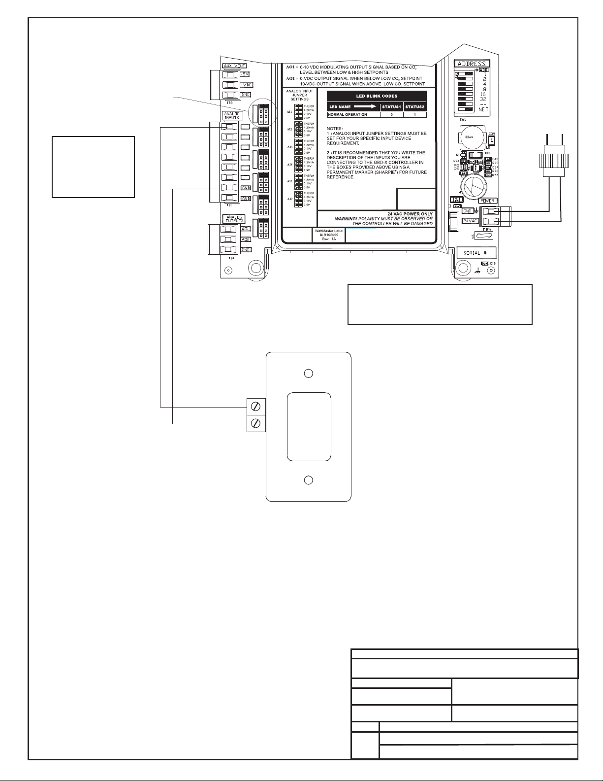
Connect The GBD-X
To The Same Local
Communications Loop
As The Controller
That Will Be
Receiving the GBD-X
Broadcast
Communications Wire
Must Be 2 Conductor
Twisted Pair With
Shield, Belden #82760
Or Equivalent.
All Wiring Must Be
Straight Through,
R To R, T To T And
SHLD To SHLD.
Available Inputs
For Connection of
Space Temperature
Sensors. See Page
4 For Detailed
Space Temperature
Sensor Wiring
AI1 SET AI2 SET AI3 SET
AI1
AI2
AI3
AI4
AI5
AI4 SET AI5 SET AI7 SET
AI7
When Used For Applications
Notes:
1.) The GBD-X Can Either Be Used
With CO2 Sensors Or Space
Temperature Sensors But Not
Both On The Same GBD-X
Controller. Up to 2 GBD
Controllers Can Be Located On
Each Local Loop.
2.) 24 VAC Must Be Connected
So That All Ground Wires
Remain Common.
OE33 -2 -
2 3 GBDX
GBD Device Wiring
-X
Space Temperature Sensor
3.) Set-up, Programming And
Monitoring Of The GBD-X
Controller Requires The Use Of A
Personal Computer And Prism
Software.
4.) All Wiring To Be In Accordance
With Local And National Electrical
Codes And Specifications.
FILENAME
FILENAME
OE332-23-GBDX-Wire1A.CDR
10/21/10
DATE:
PAGE
3of5
OE332-23- GBDX Controller
GND
24VAC
JOB NAME
JOB NAME
DRAWN BY:
DESCRIPTION:
GBD-X Wiring
Line Voltage
24 VAC Transformer
8 VA Minimum
B. CREWS
Page 9
The Jumper For The Analog Input
That Each Space Temperature
Sensor Is Connected To Must Be Set
For Thermistor As Shown For Proper
Operation Of The GBD-X Controller.
AI1 SET AI2 SET AI3 SET
Typical Wiring
Shown For Input
AI1. Wiring For
Other Inputs Is
Identical.
AI1
AI2
AI3
AI4
AI5
AI4 SET AI5 SET AI7 SET
AI7
Warning:
24 VAC Must Be Connected So That All Ground
Wires Remain Common. Failure To Do So Will
Result In Damage To The Controllers.
OE210 Space Temperature Sensor
TMP
Line Voltage
8 VA Minimum
24 VAC Transformer
GND
24VAC
Up to (6) Space Temperature
Sensors Can Be Used On The
GBD-X.
AIN1, AIN5
They Can Be Wired To
AIN2, AIN3, AIN4,
And AIN7 As Desired.
When Used For Space Temperature Sensor Averaging Applications
Notes:
1.) The GBD-X Can Either Be Used
With CO2 Sensors Or Space
Temperature Sensors But Not
Both On The Same GBD-X
Controller. Up to 2 GBD
Controllers Can Be Located On
Each Local Loop.
2.) 24 VAC Must Be Connected
So That All Ground Wires
Remain Common.
GND
OE331-21-AVG
GBD Device Wiring
3.) Set-up, Programming And
Monitoring Of The GBD-X
Controller Requires The Use Of A
Personal Computer And Prism
Software.
4.) All Wiring To Be In Accordance
With Local And National Electrical
Codes And Specifications.
FILENAME
FILENAME
OE332-23-GBDX-Wire1A.CDR
10/21/10
DATE:
PAGE
4of5
OE332-23- GBDX Controller
JOB NAME
JOB NAME
DRAWN BY:
DESCRIPTION:
GBD-X Wiring
B. CREWS
Page 10

This Switch Should Be
In The OFF Position
As Shown
ADDRESS ADD
Address Switch Shown Is
Set For Address 1
The Address For Each Controller
Must Be Unique To The Other Controllers
On The Local Loop And Be Between 1 and 60
ADDRESS ADD
Controller
Address Switch
1
2
4
8
16
32
-NET
ADDRESS ADD
Address Switch Shown Is
Set For Address 13
Note:
The Power To The Controller Must Be Removed And
Reconnected After Changing The Address Switch
Settings In Order For Any Changes To Take Effect.
Caution
Disconnect All Communication Loop Wiring From The
Controller Before Removing Power From The Controller.
Reconnect Power And Then Reconnect Communication
Loop Wiring.
AI1 SET AI2 SET AI3 SET
AI1
AI2
AI3
AI4
AI5
AI4 SET AI5 SET AI7 SET
AI7
GBD Device Wiring
Address Switch Setting Information
Notes:
1.) The GBD-X Can Either Be Used
With CO2 Sensors Or Space
Temperature Sensors But Not
Both On The Same GBD-X
Controller. Up to 2 GBD
Controllers Can Be Located On
Each Local Loop.
2.) 24 VAC Must Be Connected
So That All Ground Wires
Remain Common.
OE331-21-AVG
3.) Set-up, Programming And
Monitoring Of The GBD-X
Controller Requires The Use Of A
Personal Computer And Prism
Software.
4.) All Wiring To Be In Accordance
With Local And National Electrical
Codes And Specifications.
FILENAME
FILENAME
OE332-23-GBDX-Wire1A.CDR
10/21/10
DATE:
PAGE
5of5
OE332-23- GBDX Controller
JOB NAME
JOB NAME
DRAWN BY:
DESCRIPTION:
GBD-X Wiring
B. CREWS
Page 11

Page 12

Form: OR-GBDX-TGD-01A Printed in the USA August 2011
All rights reserved Copyright 2011
WattMaster Controls Inc. 8500 NW River Park Drive Parkville MO 64152
Phone (816) 505-1100 www.wattmaster.com Fax (816) 505-1101
 Loading...