

Page 1
www.orioncontrols.com
CO
Sensor
2
Technical Guide
Page 2
TABLE OF CONTENTS
SENSOR OVERVIEW ......................................................................................................................................... 3
Features .......................................................................................................................................................................................3
Environmental Requirements .......................................................................................................................................................3
WALL MOUNTED SPACE CO
SENSOR WIRING TO HVAC UNIT CONTROLLER .............................................. 4
2
DUCT MOUNTED CO2 SENSOR MOUNTING & WIRING TO HVAC UNIT CONTROLLER .................................. 5
DUCT MOUNTED CO2 SENSOR INSTALLATION ............................................................................................... 6
TROUBLESHOOTING ........................................................................................................................................ 8
Setting The Sensor Address Switch .............................................................................................................................................8
Using LEDs to Troubleshoot ........................................................................................................................................................8
Altitude Correction ........................................................................................................................................................................8
TB1 Terminal Block (CO2 Reading) ..............................................................................................................................................9
APPENDIX ...................................................................................................................................................... 10
Mounting Plate Dimensions........................................................................................................................................................10
PART NUMBER TABLE
PART DESCRIPTION ORION
Wall Mounted Space CO2 Sensor OE256-01
Duct Mounted CO2 Sensor (RA or SA) OE256-02
Digital Room Sensor Temp Only OE217-00
Digital Room Sensor Temp & Humidity OE217-01
Mounting Plate BK000081
VCM-X E-BUS Controller OE332-23E-VCMX
www.orioncontrols.com
WattMaster Controls Inc.
8500 NW River Park Drive · Parkville, MO 64152
Toll Free Phone: 866-918-1100
PH: (816) 505-1100 · FAX: (816) 505-1101
E-mail: mail@wattmaster.com
Visit our web site at www.orioncontrols.com
Form: OR-CO2-TGD-01E
Copyright December 2014 WattMaster Controls, Inc.
AAON® is a registered trademark of AAON, Inc., Tulsa, OK.
WattMaster Controls, Inc. assumes no responsibility for errors
or omissions.
This document is subject to change without notice.
Page 3
CO
Sensor Overview
SENSOR
2
Overview
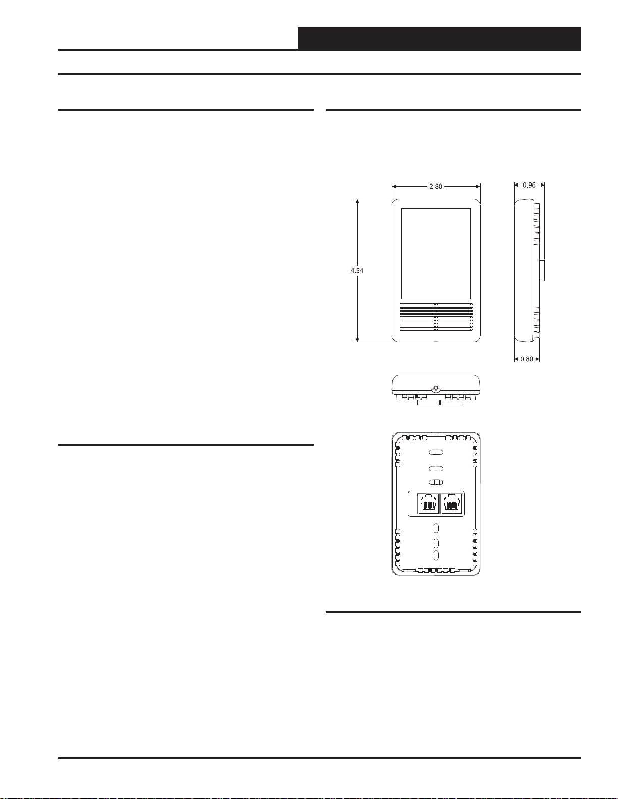
The Wall Mounted Space CO2 Sensor (OE256-01) is used for monitoring room CO
the conditioned space. It connects to the VCM-X E-BUS Controller
(OE332-23E-VCMX) or RNE Controller (OE332-23E-RNE) by using
TSDRSC modular prefabricated cable with RJ-45 connectors. It can be
daisy-chained with the Digital Room Sensor (OE217-00 or OE217-01)
or wired separately from the Orion Space T emperature Sensor (OE210,
OE211, OE212, or OE213) for applications requiring both a room CO
sensor and room temperature sensor. See Figure 1 for dimensions.
The OE256-02 Duct Mounted CO2 Sensor is comprised of the OE256-01
CO2 Sensor and the W attMaster Aspiration Box Assembly . It is used for
sensing the current CO2 level in the HVAC unit’ s return air stream. It is
designed to be mounted in the return air of the HVAC unit and uses its
integral aspiration box to sample the CO2 level in the duct.
Some typical applications are:
levels and is designed for permanent wall mounting in
2
Controlling ventilation in a building where the occupancy
varies frequently
Controlling ventilation to ensure excess outdoor air is not
causing energy waste
Ensuring good air distribution throughout building zones
Demand Control Ventilation
Environmental Requirements
The CO2 Sensor needs to be installed in an environment that can maintain a temperature range between 14°F and 122°F and a humidity range
between 5% and 95% RH (non-condensing).
2
Features
The CO2 Sensor provides the following:
Uses the patented dual beam Non-Dispersive Infrared
(NDIR) technology
A very accurate and stable sensor guaranteed to maintain
its accuracy due to infrared self-calibration feature of sensor
Sensor accuracy of +/- 50 ppm @ 1000 ppm or 2% of the
measured value
Annual drift of +/- 2 ppm per year
Measurement range of 0 to 2000 ppm
LED under front cover shows active CO
sensing
2
Addressable based on function within the system
™
Figure 1: Wall Mounted CO2 Sensor Dimensions
Technical Guide
3
Page 4
CO2 SENSOR
Wall Mounted Space CO2 Sensor Wiring to HVAC Unit Controller
Wall Mounting
The OE256-01 Wall Mounted Space CO2 Sensor utilizes a sub-base
mounting plate with a modular phone jack providing quick and easy
mounting and wiring. The wall-mounted sensor’s sub-base is compatible with standard junction boxes. A locking screw secures the assembly
to the wall.
Optional Mounting Plate
Included with the Digital Room Sensor is a mounting plate that
can be used, if necessary, to cover the sensor sheet rock opening.
This mounting plate screws onto the back of the housing base.
The mounting plate is then mounted and covers the recessed space
in the wall. A locking screw secures the sensor to the wall. See
Figure 8, page 10 for dimensions.
VCM-X E-BUS Controller
Space Temperature Sensor
OE210, OE211, OE212, OE213
(OE213 S )
NOTE: A Space Temperature Sensor Can Be
Used Instead Of the Digital Room Sensor. Either
The Slide Offset Option For The Space
Temperature Sensor Or The Remote Supply Air
Temperature Reset Signal Option (By Others) May
Be Connected To An AI7 On The VCM-X Or RNE
Controller. Only One Option Is Allowed, Not Both.
hown
TMP
W
A
R
M
GND
E
R
C
O
O
OVR
L
E
R
AUX
Wire Required For
Sensors With Slide
Adjust Option Only
AI1
AI7
GND
AI1 SET AI2 SET AI3 SET
AI1
AI2
AI3
AI4
AI5
AI4 SET AI5 SET AI7 SET
AI7
Set Jumper For
THERM When Space
Sensor Slide
Adjust Is Wired To AI7
OE256-01
Wall Mounted Space
CO Sensor
2
TSDRSC Cable
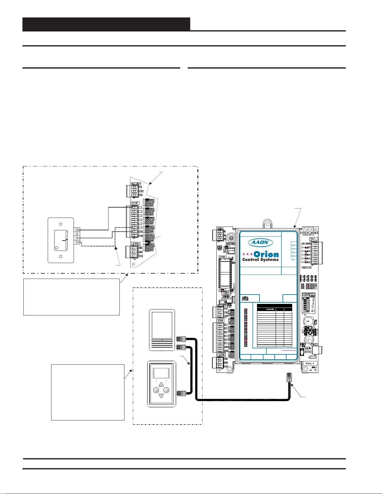
Wiring to the HVAC Unit Controller
The OE256-01 W all Mounted Space CO2 Sensor connects to the VCM-X
E-BUS or RNE Controller with the TSDRSC modular cable. It can be
daisy-chained
or used separately from a Space Temperature Sensor (OE210, OE211,
OE212, or OE213) for applications requiring both a room CO2 sensor
and room temperature sensor. Refer to Figure 2 for instructions (VCM-X
E-BUS Controller shown).
with the Digital Room Sensor (OE217-00 or OE217-01)
OE332-23E-VCMX
VCM-X E-BUS Controller
RS-485 COMMUNICATION LOOP. WIRE
“R” TO“R”, “T” TO “T” “SHLD” TO “SHLD”
RS-485 COMMUNICATION LOOP. WIRE
“R”TO “R”, “T” TO “T” “SHLD” TO “SHLD”
www.aaon.com
www.orioncontrols.com
www.orioncontrols.com
VCM-X MODULAR E-BUS CONTROLLER
Orion No.:OE332-23E-VCMX-MOD-A
OE332-23-VCMX-AVCM-X CONTROLLER
AI1 = SPC (SPACETEMPERATURE SENSOR)
AI1 = SPC (SPACETEMPERATURE SENSOR)
AI2
= SAT(SUPPLY AIR TEMPERATURE SENSOR)
AI2
= SAT(SUPPLY AIR TEMPERATURE SENSOR)
AI3
= RAT(RETURN AIR TEMPERATURE SENSOR)
AI3
= RAT(RETURN AIR TEMPERATURE SENSOR)
AI4
= OAT(OUTDOOR AIR TEMPERATURE SENSOR)
AI4
= OAT(OUTDOOR AIR TEMPERATURE SENSOR)
AI5
= SUCTION PRESSURE SENSOR (FROM EXP. MODULE)
AI5
= SUCTION PRESSURE SENSOR
AI7
= SPACETEMPERATURE SENSOR SLIDE ADJUST
AI7
= SPACETEMPERATURE SENSOR SLIDE ADJUST
OR VOLTAGE RESETSOURCE
OR VOLTAGE RESETSOURCE
A01
= ECONOMIZER (2-10 VDC OUTPUT)
A01
= ECONOMIZER (2-10 VDC OUTPUT)
= SUPPLYFAN VFD (0-10 VDC OUTPUT)
A02
A02
= SUPPLYFAN VFD (0-10 VDC OUTPUT)
E-BUS
CONNECTOR
ANALOG INPUT
ANALOG INPUT
JUMPER
JUMPER
SETTINGS
SETTINGS
THERM
LED NAME STATUS1 STATUS2
THERM
4-20mA
4-20mA
AI1
AI1
0-10V
NORMALOPERATION 0 1
0-10V
0-5V
0-5V
SATFAIL 1 2
THERM
THERM
OATFAIL 2 2
4-20mA
4-20mA
AI2
AI2
SPCFAIL 3 2
0-10V
0-10V
0-5V
0-5V
MODULEALARM 4 2
THERM
THERM
MECHCOOL FAIL 1 3
4-20mA
4-20mA
AI3
AI3
MECHHEAT FAIL 2 3
0-10V
0-10V
0-5V
0-5V
FANPROOF FAIL 3 3
THERM
THERM
DIRTYFILTER 4 3
4-20mA
4-20mA
AI4
EMERGENCYSHUTDOWN 5 3
AI4
0-10V
0-10V
0-5V
0-5V
LOWSAT 1 4
THERM
THERM
HIGHSAT 2 4
4-20mA
4-20mA
AI5
AI5
CONT.TEMP COOL FAIL 3 4
0-10V
0-10V
0-5V
CONT.TEMP HEAT FAIL 4 4
0-5V
THERM
PUSHBUTTON OVR 1 5
THERM
4-20mA
4-20mA
AI7
ZONEOVR 2 5
AI7
0-10V
0-10V
OUTPUTFORCE ACTIVE 0 6
0-5V
0-5V
ANALOG INPUTJUMPER SETTINGS
ANALOG INPUTJUMPER SETTINGS
MUSTBE SET AS SHOWN FOR
MUSTBE SET AS SHOWN FOR
PROPER OPERATION
PROPER OPERATION
STATIC
WattMaster Label
WattMaster Label
STATIC
#LB102073-01-A
PRESSURE
#LB102033-01
PRESSURE
Rev.: 1A
RELAYCONTACT
RATING IS 1AMP
RELAYCONTACT
MAX @ 24 VAC
RATING IS 1AMP
MAX @ 24 VAC
RELAY
COMMON
RELAY2
RELAY3
RELAY4
RELAY5
LED BLINKCODES
24 VAC POWER ONLY
24 VAC POWER ONLY
WARNING!POLARITY MUST BE OBSERVED
WARNING!POLARITY MUST BE OBSERVED
OR THE CONTROLLER WILLBE DAMAGED
OR THE CONTROLLER WILLBE DAMAGED
2
2
IC
IC
EXPANSION
EXPANSION
RELAY
COMMON
FAN
RELAY2
RELAY3
RELAY4
RELAY5
AAON No.:
2
IC DIGITAL
FAN
V07150
2
IC DIGITAL
SENSOR
SENSOR
POLARITY
OBSERVE
WARNING
NOTE: If The Sensor Is Used
With The Digital Room Sensor, The
CO Sensor Always Connects To The
2
VCM-X Or RNE Controller First Using
A TSDRSC Cable Of The Required
Length. The Digital Room Sensor
Then Connects To The CO Sensor
With Another TSDRSC Cable.
Total Length Of Cable For Either One
Or Both Sensor Cables Combined
Cannot Exceed 160 Feet.
CO
2
OVERRIDE ALARM
Display
Override
2
The
TSDRSC Cable
OE217-00 or OE217-01
Digital Room Sensor
Figure 2: Wall Mounted Space CO2 Sensor & Digital Room Sensor Wiring for VCM-X E-BUS Controller
4
Technical Guide
Page 5

CO
SENSOR
2
Duct Mounted CO2 Sensor Wiring to HVAC Unit Controller
Duct Mounted CO2 Sensor
The OE256-02 is comprised of the OE256-01 CO2 Sensor and the W attMaster Aspiration Box Assembly. See the dimensional and installation
information in Figures 3, below and 4 & 5, pages 6 & 7 for mounting,
wiring, and installation details.
The OE256-02 Duct Mounted CO2 Sensor is used for sensing the current
CO2 level in the HV AC unit’ s return air stream. The return air sensing use
of this sensor is applied when you want an average CO2 reading in the
area served by the HVAC unit or when you don’t want a wall mounted
CO2 due to sensor tampering concerns in the space.
VCM-X E-BUS Controller
Space Temperature Sensor
OE210, OE211, OE212, OE213
NOTE: A Space Temperature Sensor Can Be
Used Instead Of The Digital Room Sensor.
Either The Slide Offset Option For The Space
Temperature Sensor Or The Remote Supply Air
Temperature Reset Signal Option (By Others)
May Be Connected To An AI7 On The VCM-X
Or RNE Controller. Only One Option Is Allowed,
Not Both.
OE217-00 or OE217-01
Wall Mounted
Digital Room Sensor
hown
(OE213 S )
W
A
R
M
E
R
C
O
O
OVR
L
E
R
TMP
GND
AUX
Wire Required For
Sensors With Slide
Adjust Option Only
TSDRSC Cable
OVERRIDE ALARM
Display
Override
GND
AI1 SET AI2 SET AI3 SET
AI1
AI1
AI2
AI3
AI4
AI5
AI4 SET AI5 SET AI7 SET
AI7
AI7
OE256-02 Duct Mounted
OE256-02 Duct Mounted
Set Jumper For
THERM When Space
Sensor Slide
Adjust Is Wired ToAI7
SensorCO
SensorCO
2
2
The OE256-02 Duct Mounted CO
in the return air duct of the HVAC unit and uses its integral aspiration
Sensor is designed to be mounted
2
box to sample the CO2 level in the duct. Its address switch is factory set
to address “1” which is for space or return air sensing applications and
does not need to be changed for this application.
OE332-23E-VCMX
VCM-X E-BUS Controller
RS-485 COMMUNICATION LOOP. WIRE
“R” TO “R”, “T”TO “T” “SHLD” TO “SHLD”
RS-485 COMMUNICATION LOOP. WIRE
“R” TO “R”, “T”TO “T” “SHLD” TO “SHLD”
www.aaon.com
www.orioncontrols.com
www.orioncontrols.com
VCM-X MODULAR E-BUS CONTROLLER
Orion No.:OE332-23E-VCMX-MOD-A
OE332-23-VCMX-A VCM-X CONTROLLER
AI1 = SPC (SPACE TEMPERATURE SENSOR)
AI1 = SPC (SPACE TEMPERATURE SENSOR)
= SAT(SUPPLY AIR TEMPERATURE SENSOR)
AI2
AI2
= SAT(SUPPLY AIR TEMPERATURE SENSOR)
= RAT(RETURN AIR TEMPERATURE SENSOR)
AI3
AI3
= RAT(RETURN AIR TEMPERATURE SENSOR)
= OAT(OUTDOOR AIR TEMPERATURE SENSOR)
AI4
AI4
= OAT(OUTDOOR AIR TEMPERATURE SENSOR)
= SUCTION PRESSURE SENSOR (FROM EXP. MODULE)
AI5
AI5
= SUCTION PRESSURE SENSOR
= SPACETEMPERATURE SENSOR SLIDE ADJUST
AI7
AI7
= SPACETEMPERATURE SENSOR SLIDE ADJUST
OR VOLTAGE RESETSOURCE
OR VOLTAGE RESETSOURCE
= ECONOMIZER (2-10 VDC OUTPUT)
A01
A01
= ECONOMIZER (2-10 VDC OUTPUT)
= SUPPLYFAN VFD (0-10 VDC OUTPUT)
A02
A02
= SUPPLYFAN VFD (0-10 VDC OUTPUT)
E-BUS
CONNECTOR
ANALOG INPUT
ANALOG INPUT
JUMPER
JUMPER
SETTINGS
SETTINGS
THERM
LED NAME STATUS1 STATUS2
THERM
4-20mA
4-20mA
AI1
AI1
0-10V
NORMALOPERATION 0 1
0-10V
0-5V
0-5V
SATFAIL 1 2
THERM
THERM
OATFAIL 2 2
4-20mA
4-20mA
AI2
AI2
AI3
AI4
AI5
AI7
ANALOG INPUTJUMPER SETTINGS
ANALOG INPUTJUMPER SETTINGS
MUSTBE SET AS SHOWN FOR
MUSTBE SET AS SHOWN FOR
PROPER OPERATION
PROPER OPERATION
PRESSURE
PRESSURE
AI3
AI4
AI5
AI7
STATIC
STATIC
0-10V
0-10V
0-5V
0-5V
THERM
THERM
4-20mA
4-20mA
0-10V
0-10V
0-5V
0-5V
THERM
THERM
4-20mA
4-20mA
0-10V
0-10V
0-5V
0-5V
THERM
THERM
4-20mA
4-20mA
0-10V
0-10V
0-5V
0-5V
THERM
THERM
4-20mA
4-20mA
0-10V
0-10V
0-5V
0-5V
WattMasterLabel
WattMaster Label
#LB102073-01-A
#LB102033-01
SPCFA IL 3 2
MODULEA LARM 4 2
MECHC OOLFA IL 1 3
MECHHEAT FAIL 2 3
FAN PROOFFAIL 3 3
DIRTYFILTER 4 3
EMERGENCYSHUTDOWN 5 3
LOWS AT 1 4
HIGHSAT 2 4
CONT.TEMP COOL FAIL 3 4
CONT.TEMP HEAT FAIL 4 4
PUSH BUTTON OVR 1 5
ZONEOVR 2 5
OUTPUTFORCE ACTIVE 0 6
EXPANSION
EXPANSION
Rev.: 1A
RELAYCONTACT
RATING IS 1AMP
RELAYCONTACT
MAX @ 24 VAC
RATING IS 1AMP
MAX @ 24 VAC
RELAY
COMMON
RELAY
COMMON
FAN
FAN
RELAY2
RELAY2
RELAY3
RELAY3
RELAY4
RELAY4
RELAY5
RELAY5
AAON No.:
V07150
LED BLINKCODES
24 VAC POWER ONLY
24 VAC POWER ONLY
WARNING!POLARITY MUST BE OBSERVED
WARNING!POLARITY MUST BE OBSERVED
OR THE CONTROLLER WILLBE DAMAGED
OR THE CONTROLLER WILLBE DAMAGED
2
2
IC
IC
2
2
IC DIGITAL
IC DIGITAL
SENSOR
SENSOR
OBSERVE
POLARITY
WARNING
NOTE: If The Sensor Is Used WithThe Digital
Room Sensor, The CO Sensor Always Connects To
The VCM-X Or RNE Controller First Using A TSDRSC
Cable
Sensor Then Connects To The CO Sensor With
Another TSDRSC Cable. The Total Length Of Cable
For Either One Or Both Sensor Cables Combined
Cannot Exceed 160 Feet.
CO
2
2
Of The Required Length. The Digital Room
2
TSDRSC Cable
Figure 3: Duct Mounted CO2 Sensor & Digital Room Sensor Wiring for VCM-X E-BUS Controller
Technical Guide
5
Page 6

CO2 SENSOR
Duct Mounted CO2 Sensor Installation
Duct Mounted CO2 Sensor Installation
To install the Duct Mounted CO2 Sensor, please follow the instructions
below. See Figures 4 & 5 for detailed illustrations of the Duct Mount-
ed CO
Sensor and its components.
2
STEP 1: Find the general location on the side of the Return Air
Duct where you want to mount the CO2 Sensor. Be sure to locate
the box with the airfl ow in the proper direction per the airfl ow
label. Using the Aspiration Box as a template, draw around it with
a pencil on the duct. Locate the center of the box you have drawn
and mark it. Using a 1 1/4” hole saw, drill a hole in the duct wall
using the center you have just drawn as the drilling point. Insert
the aspiration tube into the hole in the duct and mount the Aspiration Box to the Duct using a power screwdriver to secure the (4)
mounting feet to the Duct wall using the (4) supplied sheet metal
screws.
STEP 2: Remove the Aspiration Box cover from the Aspiration
Box base by loosening the (4) screws that secure it with a Phillips
screwdriver. Using the Phillips screwdriver, loosen the (2) conduit
clamp screws on the conduit clamp assembly located on the side
of the Aspiration Box enough to allow the insertion of the RJ-45
male cable connector(s) and cable(s) through the cable clamp
opening and into the Aspiration Box using the appropriate length
pre-fabricated TSDRSC cable(s) or TSDRSC & FMRSC cable(s)
as required by your application.
STEP 5: After setting the address switch (if required), re-install
the Sensor cover with circuit board to the Sensor base using the
supplied Allen wrench and set screw and re-install the Aspiration Box cover in reverse fashion from how you disassembled it
previously.
STEP 6: Tighten the conduit clamp screws down until the
conduit clamp is gripping the Sensor cable(s) snuggly. Do not
over-tighten the clamp screws as this could damage the cable(s).
STEP 3: Remove the CO2 Sensor cover with circuit board by
using the included Allen wrench to loosen the set screw located
at the bottom edge of the CO2 Sensor assembly and pulling the
Sensor cover with circuit board apart from the Sensor base. Route
the RJ-45 male plug(s) and cable(s) under the Sensor base and
through the rectangular clearance opening in the Sensor base and
then plug the RJ-45 male cable connector(s) into the RJ-45 female
connector(s) on the back of the Sensor circuit board which is attached to the Sensor cover.
STEP 4: The address switch is factory set to “1” which is correct for Space CO2 Sensor applications or Return Air CO2 Sensor
applications. If you have a custom coded application and need to
change the address switch, setting the address switch at this time
is a good idea as it requires taking the Sensor base apart from the
Sensor cover. See page 8 for instructions. It will also require that
you power up the VCM-X Controller that the Sensor is plugged
into to perform the address setting procedures.
Figure 4: CO2 Sensor Components and Wiring
6
Technical Guide
Page 7

CO
SENSOR
2
Duct Mounted CO2 Sensor Installation
Figure 5: Mounting and Cable Installation for Duct Mounted CO2 Sensor
Technical Guide
7
Page 8

CO2 SENSOR
Troubleshooting
Setting the Sensor Address Switch
LED ON/OFF Push-Button Operation for Setting
Address
The LED ON/OFF Push-Button is used to set the CO2 Sensor’s address.
The LED ON/OFF Push-Button is located on the Sensor’s board and is
only visible by taking the device off the wall. See location in Figure 6.
The default addresses are as follows:
• Space or Return CO2 Sensor = Address 1 (Default)
• Address 2 is reserved.
• Open addresses for Custom Applications = Addresses 3-10
To set the address, follow these instructions:
1. Power up the VCM-X or RNE Controller that the Sensor is
plugged into.
2. Press the LED ON/OFF Push-Button for 5 seconds until the
LEDs turn off.
3. Then press the push-button the number of times that represents the address. Press once for address 1, press twice for
address 2, etc.
4. The address range can be set to 1 (default) and from 3 to 10.
5. To verify that the correct address has been entered, refer to
the STATUS LED information below.
The board address is stored in nonvolatile memory. Once the address is
set, the address will be saved after loss of power.
Using LEDs to Troubleshoot
LEDs are available for troubleshooting the CO2 Sensor. The Front LED
is visible through the front cover of the CO
location. The other LEDs are located on the Sensor’s board and are only
visible by taking the device off the wall. See Figure 6 for locations.
LED ON/OFF Push-Button
This button is located on the CO2 Sensor’s board. See Figure 6. This
button is initially set for “LEDs OFF .” Push this button to enable/disable
the LEDs. Pushing this button ON will make Front LED light up. This
LED is also used for setting the address.
Front LED
When the LEDs are turned on, a green LED will be visible through the
front plastic cover of the CO2 sensor. See Figure 7. The Front LED
will blink whenever a CO2 sample is taken. A sample is taken every
30 seconds.
STATUS LED
Initially, the STATUS LED blinks fast for 30 seconds. It then stays on
and blinks the board address whenever a CO2 sample is taken. A CO2
sample is taken once every 30 seconds.
COMM LED
The COMM LED blinks on whenever communications are sensed.
Sensor. See Figure 7 for
2
Altitude Correction
Altitude correction can be confi gured using Prism software installed on
a computer. The altitude can be confi gured at a value of 0-15,000 feet.
The default is 500 feet.
8
Technical Guide
Page 9

TB1 Terminal Block (CO2 Reading)
The TB1 terminal block should only be used to test the sensor when the
sensor cable is plugged into the controller and the sensor and controller
are powered up. Directions: Set the meter for DC volts and connect
the GND probe to the GND terminal and the + probe to the CO
terminal. Look at the output voltage and record it. Multiply the voltage
times 400. The value should match the CO2 as read on the System Manager TS, Modular System Manager, Modular Service Tool, or Prism. If
the signal doesn’t match the sensor reading, call WattMaster Controls
for a replacement.
0-5
2
CO
Troubleshooting
Figure 7: CO2 Sensor’s Front LED
SENSOR
2
Figure 6: LED ON/OFF Button and Board LEDs
Technical Guide
9
Page 10

CO2 SENSOR
1.638
1.810
0.882
1.407
1.842
0.733
2.110
2.920
0.810
R0.220
3.275
0.060
0.160
5.037
3.278
3.766
4.153
Appendix - Mounting Plate Dimensions
Optional Mounting Plate
Included with the Digital Room Sensor is a mounting plate that
can be used, if necessary, to cover the sensor sheet rock opening.
This mounting plate screws onto the back of the housing base.
The mounting plate is then mounted and covers the recessed space
in the wall. A locking screw secures the sensor to the wall. See
Figure 8, below for dimensions.
Figure 8: BK000081 Mounting Plate Dimensions
10
Technical Guide
Page 11

CO
SENSOR
2
Notes
Technical Guide
11
Page 12

Form: OR-CO2-TGD-01E Printed in the USA December 2014
All rights reserved. Copyright 2014
WattMaster Controls Inc. 8500 NW River Park Drive Parkville, MO 64152
Phone: 866-918-1100 www.orioncontrols.com Fax (816) 505-1101
 Loading...