

Page 1
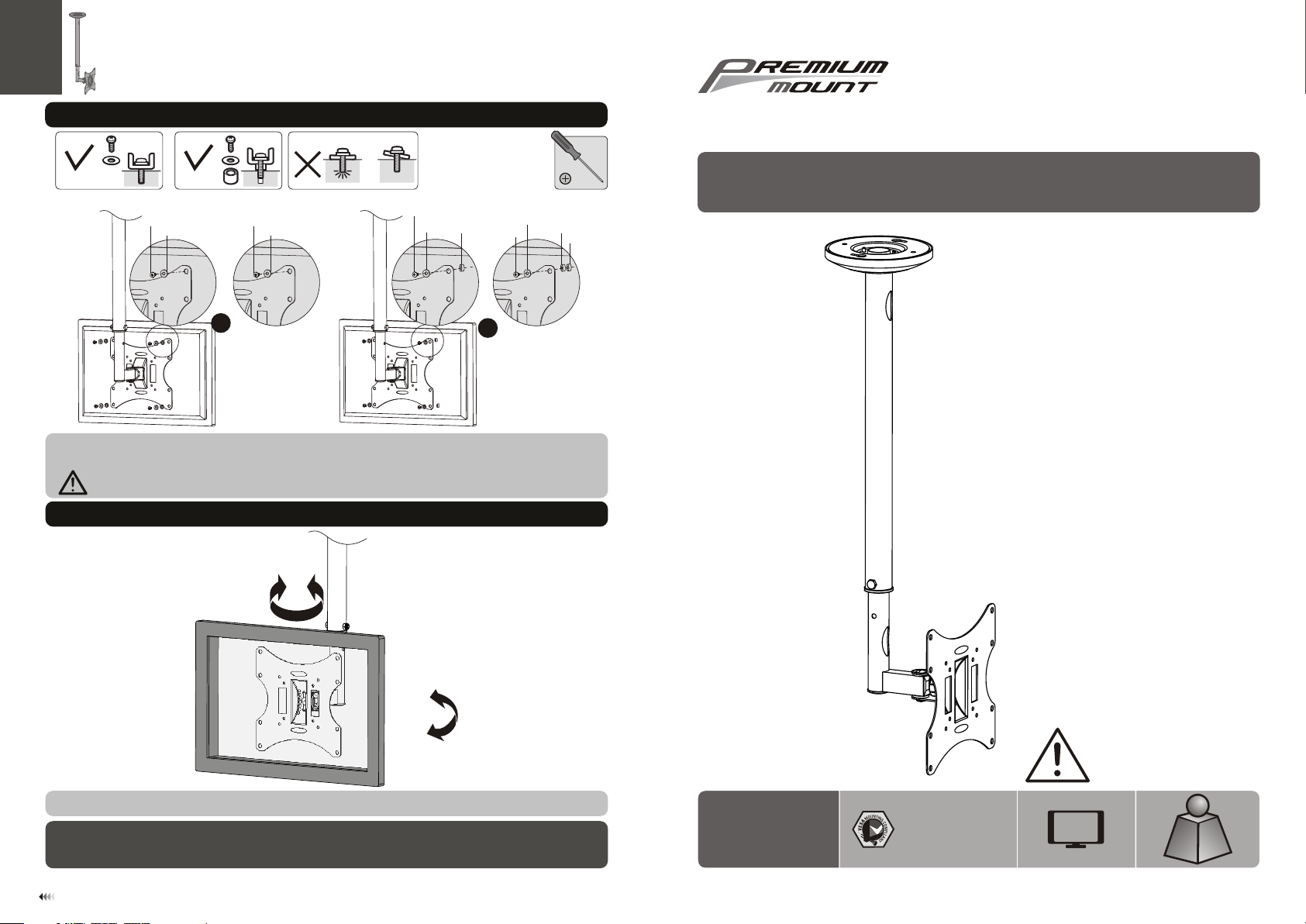
6. Installing the Display
730 0 Bolsa Av e., W est minst er, CA 9268 3 -
Pre mium Mo unt Inc
Pho ne: 714 -766- 6303
INSTALLATION MANUAL
TVTV
M-A
M-B
M-E
Not e: Choose the ap pro pri ate scre ws, wash ers and spa cers (if necessa ry) according to th e type of scr een .
Lift the disp la y an d ma tch the holes on yo ur d is pl ay with the hol es o n th e mo un t. Secure you r di sp la y to
the mount by ti gh te ni ng screws.
Tig ht en a ll s cr ews but do not ov er t ig ht en.
M-C
M-D
M-F
or
TV
TV
M-D
M-F
M-G
M-F
M-G
M-D
or
M-G
7. Adjustment
18 0 °
LCD Ceiling Mount
+2 0 °
-2 0 °
Use the tilt ad ju st in g knob to adjust yo ur d is pl ay to the desir ed a ng le t he n tighten it.
Maintenan ce
• Check that th e br ac ke t is secure and s af e to u se a t re gular inter va ls (a t le ast every thr ee m on th s) .
• Please cont ac t yo ur d ealer if you have a ny q ue st ions.
7
CMK-01
75x75/100 x1 00
200x100/2 00 x2 00
CA UT ION : DO N OT EX CE ED
RATE D LI STE D WE IGH T. SER IOU S
INJ URY O R PROPE RTY DAM AGE
MAY OCCUR !
37"
MAX
(66lb s)
(66lb s)
RATE D
RATE D
ISSUED: FEB. 2013
30kg
30kg
Page 2
NOTE : Re ad the enti re instru ct ion manua l before yo u st art insta llation a nd a ssembly.
WARNING
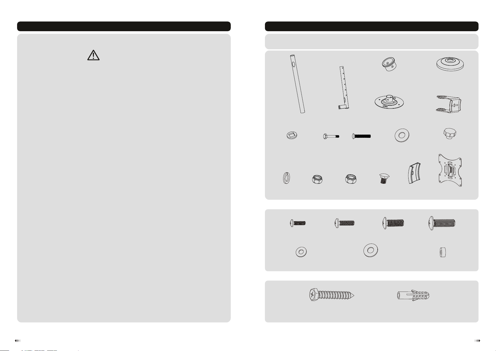
Component Checklist
IMPO RTANT: En sure th at y ou ha ve r ec eiv ed a ll part s ac cor di ng to the c om ponen t ch eck li st prio r to i nstal la tio n.
If an y pa rt s are m is sing or f au lty, t eleph on e your lo ca l dis tr ibuto r fo r a repla ce men t.
• Do not begin the installation until you have read and understood all the instructions
and warnings contained in this installation sheet. If you have any questions
regarding any of the instructions or warnings, please contact your local distributor.
• This mounting bracket was designed to be installed and utilised ONLY as
specified in this manual. Improper installation of this product may cause damage
or serious injury.
• This product should only be installed by someone with good mechanical ability
who has basic building experience and fully understands this manual.
• Make sure that the supporting surface will safely support the combined weight of
the equipment and all attached hardware and components.
• If mounting to wooden joist ceiling, make sure that mounting screws are anchored
into the center of the joist. The use of a stud finder is highly recommended.
• Always use an assistant or mechanical lifting equipment to safely lift and position
the equipment.
• Tighten screws firmly, but do not over tighten. Over tightening can cause damage
to the items, This greatly reduces their holding power.
outer column (x1)
M8 washer (x2 )
washer (x1)
L
Pack age M
M4x14 (x4)
A
G
M-A
M6x45(x2)
M6 nut (x2)MM8 nut (x1)
Inner column (x1)
B
H
M8x45(x1)
N
M5x14 (x4)
M-B
plastic bushing (x2)
ceiling plate (x1)
I
M8x20 (x1)
C
E
D8 washer (x2 )
J
plastic pad (x1)
O
M6x14 (x4)
M-C
plastic cover (x1)
D
grip holder (x1)
F
M8 (x1)
K
P
VESA plate Q(x1)
M8x20 (x4)
M-D
• This product is intended for indoor use only. Using this product outdoors could
lead to product failure and personal injury.
D5 washer (x4 )
Pack age W
M-E
ST6.3x55 (x 4)
W-A
D8 washer (x4 )
M-F
small space r (x 8)
concrete an ch or ( x4 )
W-B
M-G
21
Page 3

1a. For Wooden Joist Ceiling Mounting
XX
55mm
55mm
55mm
(2.2")
2.2"( )
(2.2")
ø 4.5mm
(ø 3/16")
1
Fin d and mark
the e xac t loc ation
of mo unt ing holes
2
3
Drill two
pilot holes
1b. Solid Brick and Concrete Block Mounting:
1b. For Solid Brick and Concrete Mounting
3mm
60mm
60mm
60mm
2.4"( )
(2.4")
(2.4")
ø 10mm
(ø 3/8")
1
Mar k the e xac t
loc ation of
mou nting
hol es
2
Drill four
pilot holes
W-A
Screw the
W-A
Hang the cei ling plate so that the screws
fit in to the keyho le ope nin gs. Turn the
ceiling plate into place an d then tight en
the sc rews.
ceiling plate
onto the
ceiling
WARNING
• Make sure that mounting screws are anchored into the center of the joist. The use of a stud
finder is highly recommended.
• Installers are responsible to provide hardware for other types of mounting situations.
• Installers must verify that the supporting surface will safely support the combined weight of the
equipment and all attached hardware and components.
3
3mm
W-B
Screw the
W-A
Hang the ceil in g pl at e so that the screw s fi t in to t he keyhole op en in gs . Tur n the ceiling p la te i nt o pl ace .
Do not tighte n sc re ws a t this time. Fi x th e ce il in g plate using t he t wo o th er s crews and the n ti gh te n al l
the screws!
ceiling plate
onto the
ceiling
WARNING
Instal lers must verify that th e supporting surface will safely support the combin ed weight of
the equipment and all attached hardwar e and components.
4
Page 4

2. Installing the Outer Column to the Ceiling Plate
4. Assembling the VESA Plate
H
3. Installing the Inner Column and Routing Cables
Run the power c ab le
through col um ns .
K
C
M
L
O
J
P
5. Installing the VESA Plate
I
G
H
Insert plas ti c bu sh ing and inner col um n in to t he outer colu mn a nd f ix t he m at the desire d he ig ht u si ng the
correct com bi na ti on of screw and nut .
M
C
G
J
N
65
 Loading...