

Page 1
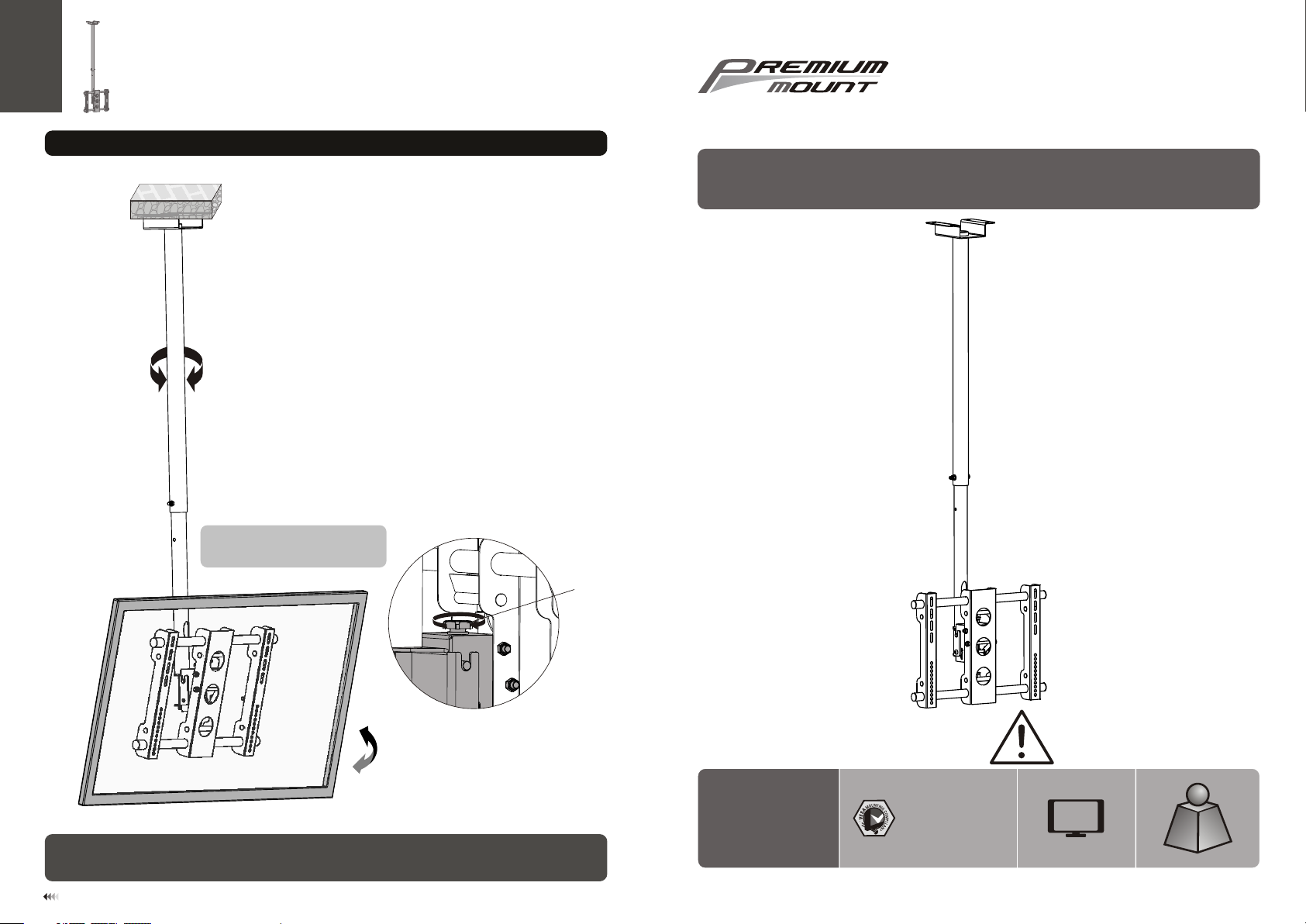
6. Adjustment
360 ° 360 ° 360 °
Lo os e th e knob to tilt the desi re d
an gl e th en t ighte n it .
730 0 Bolsa Av e., We stm inst er, CA 92 683 -
Pre mium Mo unt Inc
Pho ne: 714 -766- 6303
Flat Panel Ceiling Mount
INSTALLATION INSTRUCTIONS
+1 5°
-
1
°5
Maint ena nce
• Check t hat t he br ack et is s ecure and sa fe to u se at r egu lar intervals (at l eas t eve ry three months ).
• Pleas e con tac t you r dealer if you hav e any q ues tio ns.
11
Knob
CMH -01
400x2 00/ 400 x40 0
600x4 00/ 800 x40 0
CA UTI ON : DO NOT EXCE ED MA XIMUM
LIS TED W EIG HT CAPA CIT Y. SE RIOU S
INJURY OR P ROP ERTY DAMA GE MAY
OCCUR!
63"
MAX
75kg
75kg
(165lbs)
(165lbs)
MAX
MAX
ISSUED: NOV. 2012
Page 2
NOTE: Rea d the entire instr uction manual be fore you st art ins tallati on and as sembly.
WARNING
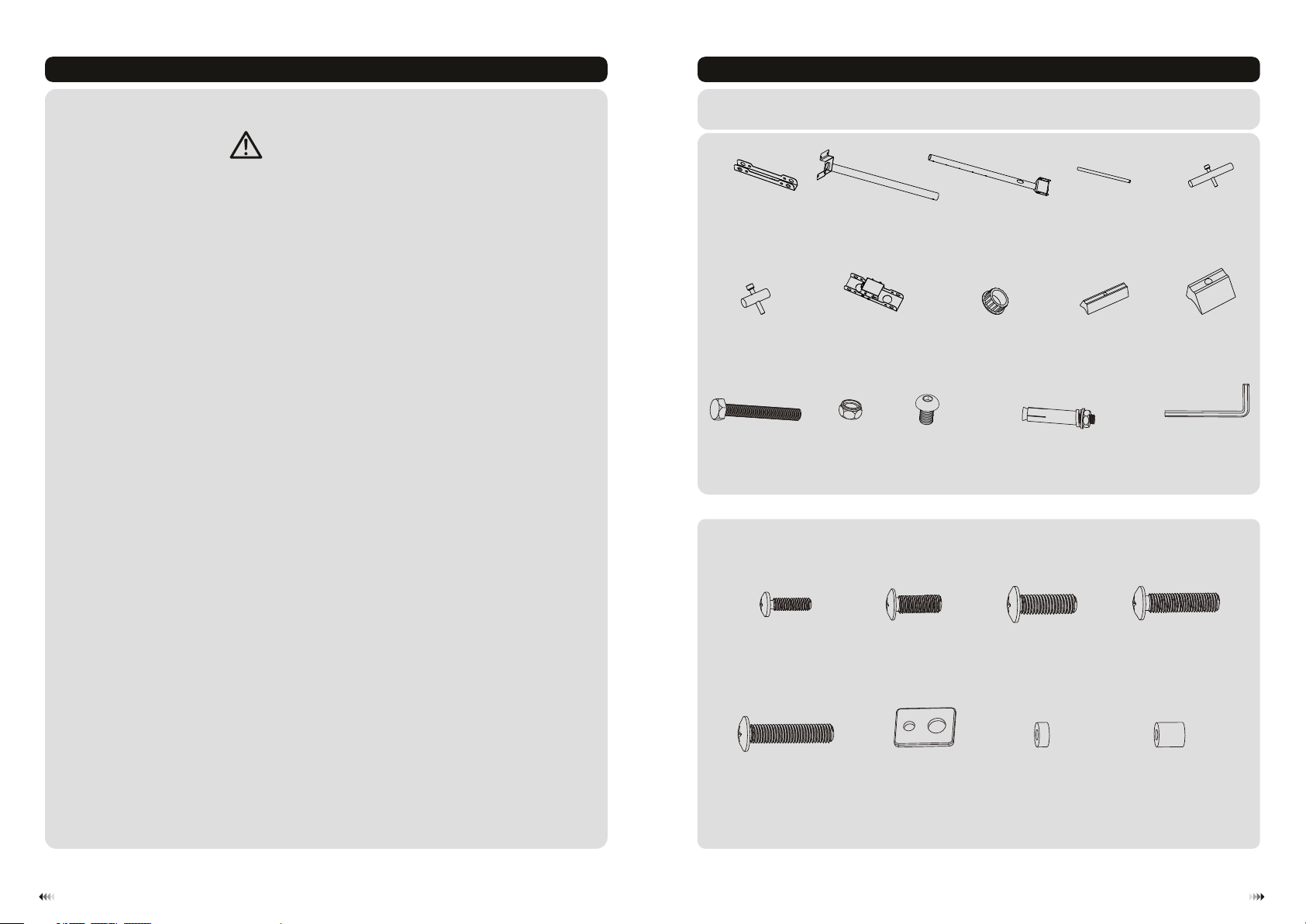
Component Checklist
IMPORTANT: En sure that y ou ha ve re cei ved all par ts ac cor din g to the comp one nt ch eck list prio r to in sta lli ng. If
any p art s are m iss ing or faulty, te lep hone your l oca l dis tri butor for a r epl ace men t.
• Do not begin the installation until you have read and understood the instructions
and warnings contained in this installation sheet. If you have any question
regarding any of the instruction or warning, please contact your local distributor.
• This mounting bracket was designed to be installed and utilized ONLY as
specified in this manual. Improper installation of this product may cause damage
or serious injury.
• This product should only be installed by someone of good mechanical ability,
with basic building experience and fully understanding of this manual.
• Make sure that the supporting surface will safely support the combined load of
the equipment and all attached hardware and components.
• Always use assistant or mechanical lifting equipment to safely lift and position
equipment.
• Tighten screws firmly, but do not over tighten. Over tightening can damage the
items, greatly reducing their holding power.
• This product is intended for indoor use only. Using this product outdoors could
lead to product failure and personal injury.
adapter bracket (x2)A top pipe (x1)
axle pin &
safety bolt (4)
F
M8x60 K(x1)
arm ass emb ly( x1)
G
M8 nut (x1)
L
Package M
M5x14 ( x4)
M-A
B
M8x 16( x2)
M6x14 ( x4)
M-B
bottom pipe (x1)C1"dia met er tu be( x2)
M-C
vise assembly
(big) (x2)
N
M
plastic cover(4)
H
M8 (x4)x70 iro n exp ans ion b olt
M8x20 ( x4)
D
I
axle pin &
safety bolt (x2)
vise assembly
(small) (x4)
5 A 2
mm llen key (x )
M6x30 ( x4)
M-D
E
J
O
M8x30 ( x4)
M-E
washe r
M-F
(x4)
small s pac er (x 8)
M-G
big spa cer ( x4)
M-H
21
Page 3

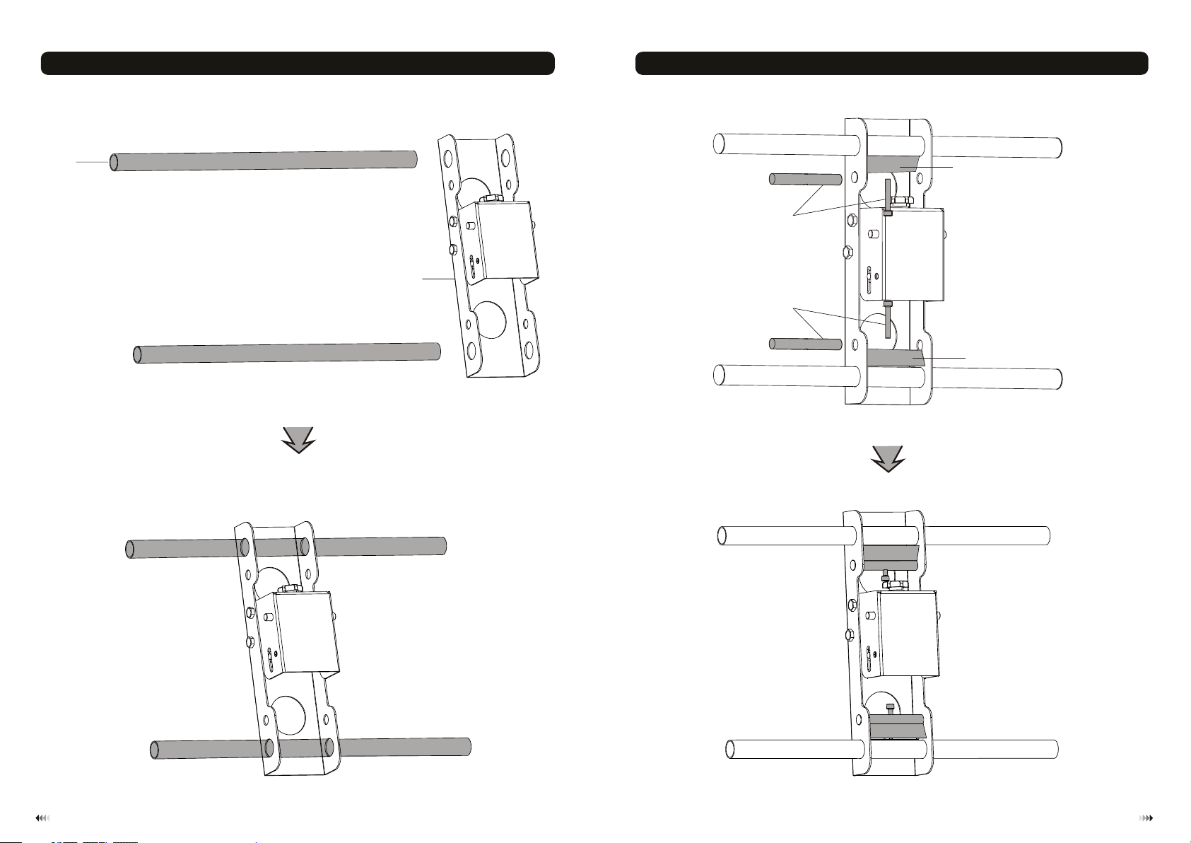
1. Assemble Pipes
Run pow er ca ble t hro ugh pipe.
1b. Solid Brick and Concrete Block Mounting: 1b. Solid Brick and Concrete Block Mounting: 2.Mount on Solid Brick and Concrete Block
60mm
60mm
45mm
2.4"( )
(2.4")
(1.8")
ø 12mm
(ø 1/2")
Mark th e exa ct
locat ion o f
mount ing h ole s
1
N
2
Drill four
pilot holes
B
Screw ceiling
mount on the
ceiling
C
L
K
Tig hten all nuts but d o not o ver
tight en.
WARNING
• When installing ceiling mounts on cinder block, verify the actual concrete thickness is at least
1-3/8" (35 mm) for using the concret e anchors. Do not drill into mortar joints! Be sure to
mount in a soli d part of the block, generally 1" (25mm) minimum from the side of the block.
It is suggested electric drill on slow setting be used to drill the hole instead of a hammer drill
Attac h bot tom p ipe t o top p ipe and
fix the m at th e des ire d height. Using
corre ct co mbi nat ion of screw and nu t.
3
to avoid breaking out the back of the hole when entering a void or cavity.
• Installers must veri fy that the sup porting su rface will safely support the combi ned load of the
equipment and all attached hardware and components.
4
Page 4
1b. Solid Brick and Concrete Block Mounting: 3. Assemble the Universal Plate
D
E
G
E
I
I
65
Page 5

A
H
J
F
7 8
Page 6
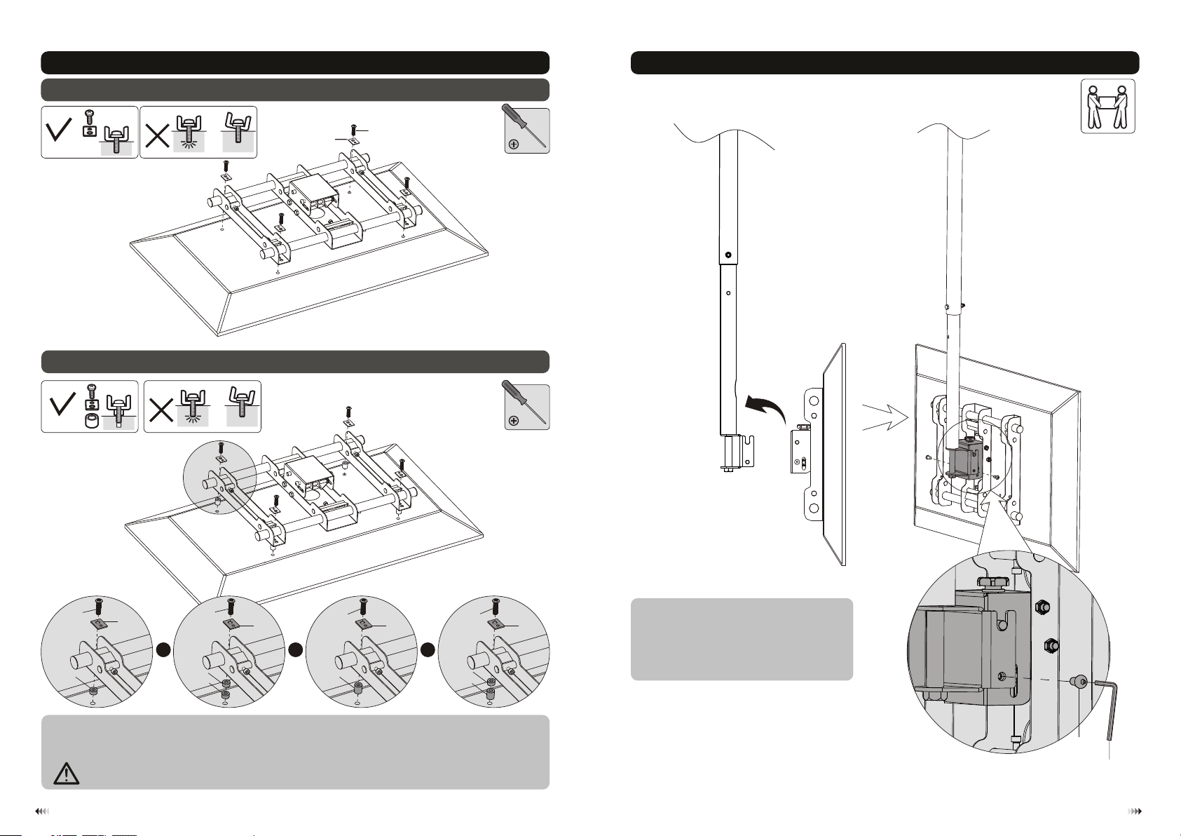
4. Install the Universal Plate
4-1 For Flat Back Screen
5. Hang TV onto the Universal Plate
TV
TV
TV
4-2 For Recessed Back Screen or to Access A/V Inputs
TV
TV
TV
M-F
M-A/M -B/ M-C
M-C
M-F
M-C
M-D
M-E
M-F
M-D
M-E
M-F
M-D
M-E
M-F
or or or
M-G
M-G
M-G
M-H
M-G
M-H
Note: C hoo se ap pro priate screws , was her s and s pacers (if nece ssa ry) a cco rding to the type o f scr een .
· Posit ion t he un ive rsal plate as clo se as p oss ibl e to the middle of th e scr een .
· Screw t he un ive rsa l plate onto the TV.
Tig hten all screws b ut do n ot ov er ti ghten.
Tig hte n the s afety screws to s ecu re th e
unive rsa l pla te to t he ceiling moun t.
Make su re th e TV is safe ly se cur ed be fore
relea sin g.
M
O
109
 Loading...