

Page 1
Installation and User’s Guide
1/3” CMOS HIGH SENSITIVE DAY/NIGHT HD CCTV
CHDC-21BSDC
HD CCTV CAMERA
Installation and User’s Guide
http://www.orionimages.com
All contents of this document may change without prior notice, and actual product appearance may differ
from that depicted herein
Page 2

http://www.orionimages.com
Installation and User’s Guide
THANK YOU FOR CHOOSING ORION
Thank you for choosing ORION Images high quality HD CCTV Camera.
Please read this instruction manual carefully to keep yo ur ORION Images product at peak performance
for longer service duration. All ORION Images products are designed and manufactured with utmost
care and craftsmanship to provide long life and high quality performance, if it is properly used and
maintained as outlined in this manual. This high performance HD CCTV camera is eq uipped with a 1/3”
FHD CMOS sensor, which has extremely wide range of uses in many different applications and
conditions.
CONTENTS OF CHDC-21BSDC MANUAL
1. Handling precautions………………………………………………………………......
Pg4
2. General…………………………………………………………………………………..
3. Package of Content…………………………………………………………………….
4. Features………………………………………………………………………………….
5. Name of parts and functions…………………………………………………………...
6. Operation…………………………………………………………………………………
Pg4
Pg4
Pg5
Pg6-7
Pg8
6.1. User setup…………………………………………………………………………..
6.2. SETUP switches and function…………………………………………………….
6.3. Entering the setup mode and its basics………………………………………….
6.4. Setup procedures…………………………………………………………………..
7. Specifications…………………………………………………………………………….
Pg8
Pg8
Pg9-16
Pg16
Pg17
8. Outline Dimension……………………………………………………………………….
9. Warranty and after-sale service………………………………………………………..
Pg18
Pg19
10. Setup Menu Flow Chart
2
7300 Bolsa Avenue, Westminster CA 92683 / Tel: 714-766-6300 / Fax: 714-766-6310
pg2
Page 3
quip
http://www.orionimages.com
Installation and User’s Guide
The exclamation point within an equilateral triangle is intended to alert the user to
the presence of important operating and maintenance (serv icing) instructio ns in the
literature accompanying the appliance.
CAUTION
NOTE:
This equipment has been tested and found to comply with the limits for a Class A digital device.
Pursuant to Part 15 of the FCC Rules. These limits are designed to provide reasonable protection
against harmful interference in a residential installation. This equipment generates, uses and ca n
radiate radio frequency energy and, if not installed and used in accordance with the instructions,
may cause harmful interference to radio communication. However, there is no guarantee that
interference will not occur in a particular installation. If this equipment does cause harmful
interference to radio or television reception, which can be determined by turning the equipment off
and on, the user is encouraged to correct the interference by one or more of the following measures.
CAUTION:
ANY CHANGES OR MODIFICATIONS NOT EXPRESSLY APPROVED BY THE PART
RESPONSIBLE FOR COMPLIANCE COULD VOID THE USERS AUTHORITY TO OPERATE THE
EQUIPMENT.
Instructions for Disposal of Electrical and Electronic Equipment in Private Households
By ensuring this product is disposed of correctly, you will help prevent possible negative consequences
for the environment and human health which could other wise caused by inappropriate handling of this
product. The correct recycling of materials will help to conserve natural resources.
For more detailed information about recycling of this product, please contact your local c it y authorit y, your
household waste disposal service or the place wher e you purchased the product.
Disposal of used Electric and Electronic Equipment (Applicable in the European
Union and other European countries with waste recycling, disposal and
collection regulations)
This symbol on the product, or in the related documents in the package, indicates that
this product shall not be treated as normal household waste. Instead, it should be
taken to a proper applicable collection point or depot for the recycling of electrical and
electronic e
ment.
3
7300 Bolsa Avenue, Westminster CA 92683 / Tel: 714-766-6300 / Fax: 714-766-6310
pg3
Page 4
http://www.orionimages.com
1. HANDLING PRECAUTIONS
Installation and User’s Guide
z Do not install the camera in a water-splashed or highly humid environment.
z Do not use the camera where the ambient temperature drops below 0° C or rises above +50° C. The
images and component parts may be adversely affected or the camera may not function correctly.
z Never open the camera case because there are precision electrical and electronic comp onents inside
and an accident may results.
z Do not put anything metallic or any other foreign substances through the vent, as a fire or electric
shock may result.
z Be sure to turn off the power before installing or making connections.
z Do not install the camera in places exposed to heat, vibrations and shock.
z Be careful not to drop or give a strong shock to the camera while transporting it.
z Do not touch the image sensor.
z Do not orientate the camera directly towards the sun.
z Some types of lenses may hunt in adverse light conditions. In such cases please re-adjust the lens in
line with the instructions in the manual.
z Because of the characteristics of the digital image device, images may look unnatural at high
temperatures, this does not mean the camera is faulty.
2. GENERAL
This HD CCTV Camera is provided with a High performance 1/3 inch 2.1M CMOS sensor. The
camera features a highly sensitive with high resolution, and is equipped with digital DAY/NIGHT
function, intelligent back-light compensation by which you can achieve proper Back Light
Compensation, Automatic iris control, Crystal controlled internal sync lock system, Various modes of
convenient Automatic while balancing, mirror image, private mask function, motion detection, camer a
setup and control is also possible locally on the camera real panel, or remote via RS-232C and this
setup data is stored in the built-in non-volatile memory. The camera is best suited for HD CCTV
surveillance purposes, from single camera operation to large scale integrated systems for visual
information management.
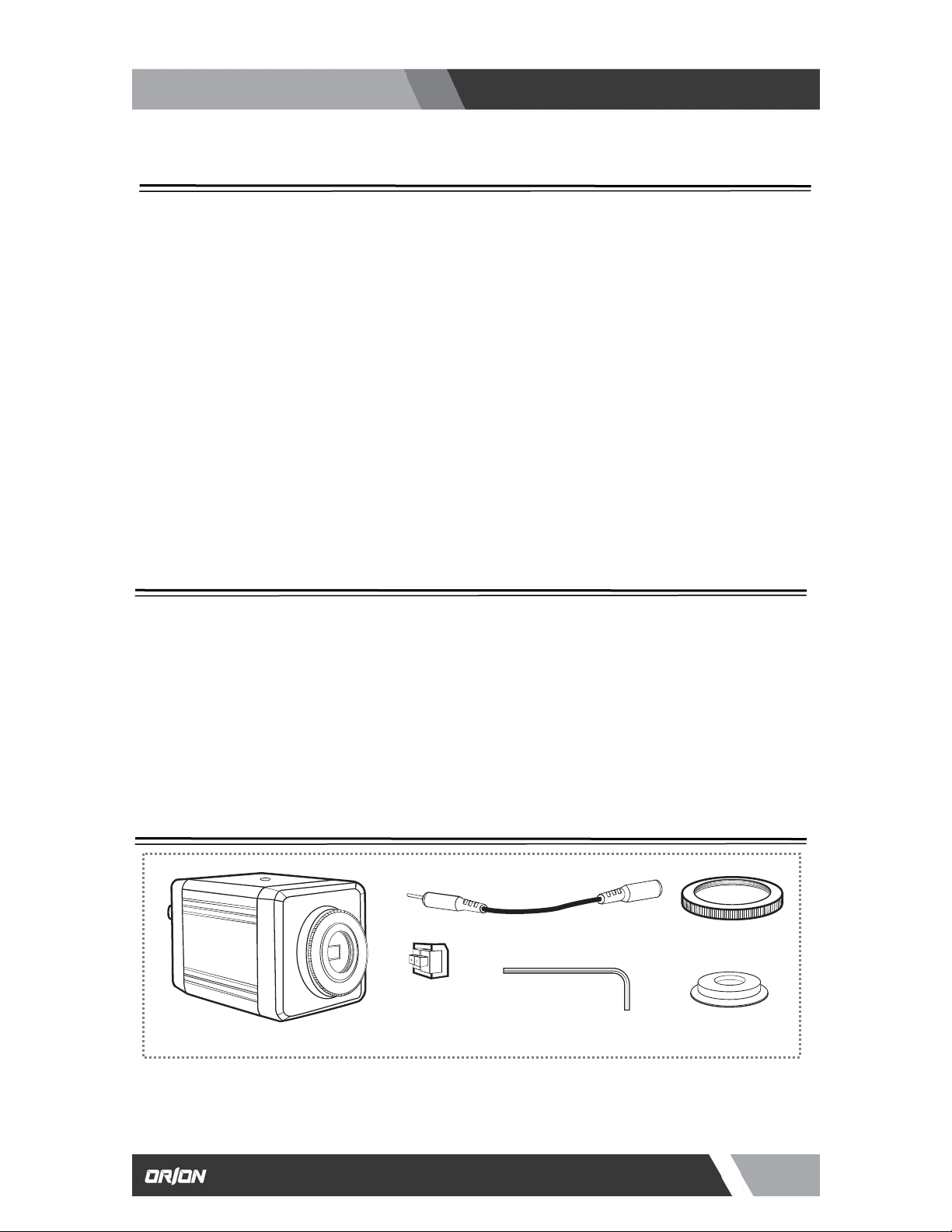
3. PACKAGE OF CONTENT
DC Power Cable x 1
C-Mount Ring x 1
CHDC-21BSDC Camera x 1
DC Power Female
Connector
Hexagon Ranch x 1
Lens Mount Cap x 1
4
7300 Bolsa Avenue, Westminster CA 92683 / Tel: 714-766-6300 / Fax: 714-766-6310
pg4
Page 5

http://www.orionimages.com
4. FEATURES
1 HD-SDI OUTPUT
This camera outputs and HD-SDI signal featuring resolutions of 1920 x 1080p (30 / 25) or
1280 x 720p (60 / 50) SMPTE 274M standard.
2 TEST COLOR BAR
A built-in the Test Color Bar signal makes easy for adjustment.
3 NTSC / PAL OUTPUT
This output can be used for a test or an adjustment of the lens or camera angle when
installed.
4 DAY / NIGHT FUNCTION
This camera delivers high quality color images during the day. As light diminishes below a
certain level, the camera can automatically switch to night mode to make use of near-infrared
(IR) light to deliver high-quality, black and white images.
5 BACK LIGHT COMPENSATION
Well-designed BLC, back light compensation, facility is provided which can assign a
compensation area for back light compensation to have an optimum b alanced clear picture
reproduction.
6 TWO-WAY AUTOMATIC IRIS CONTROL
This function is available to switch between Video type iris lens and DC t ype iris lens. In other
words, almost all types of automatic iris CCTV lenses can be used.
7 AUTOMATIC OR MANUAL WHITE BALANCE
In addition to the Auto white balance, this camera provide manually adjustment of Red / Blue
Gamma.
8 ELECTRONIC SHUTTER
A smooth control to compensate sensitivity variation with an electronically controlled Autoshutter. Also manual shutter mode can be selected to capture the fast moving object (manual
shutter speed – 1/30, 1/60, 1/120, 1/250, 1 /700, 1/1000, 1/1600, 1/2500, 1/5000, 1/7000,
1/10000, 1/30000).
9 PRIVACY MASKING FUNCTION
The camera comes equipped with privacy masking, which covers sensitive areas in the
screen that need to remain unseen. Yo u can assign a maximum of 32 zones with adjustable
size area to hide with this masking function.
10 LENS FLANGE BACK FOCUS ADJUSTMENT
An easy adjustment can be done by using a hex driver pr ovided. This may be useful when
changing lens from single focal lens, vari-focal lens, long lens, or zoom lenses, or vice versa.
11 MOTION DETECTION
This camera comes with motion detection, which covers sensitive areas in the screen that
need to detect the motion. You can assign a maximum of 4 zones with adjustable size area.
12 MIRROR IMAGE
This flips the image horizontally or vertically.
13 CAMERA ID
Information can be inserted in the screen.
Installation and User’s Guide
5
7300 Bolsa Avenue, Westminster CA 92683 / Tel: 714-766-6300 / Fax: 714-766-6310
pg5
Page 6
③
(
used
④
⑤
⑥
http://www.orionimages.com
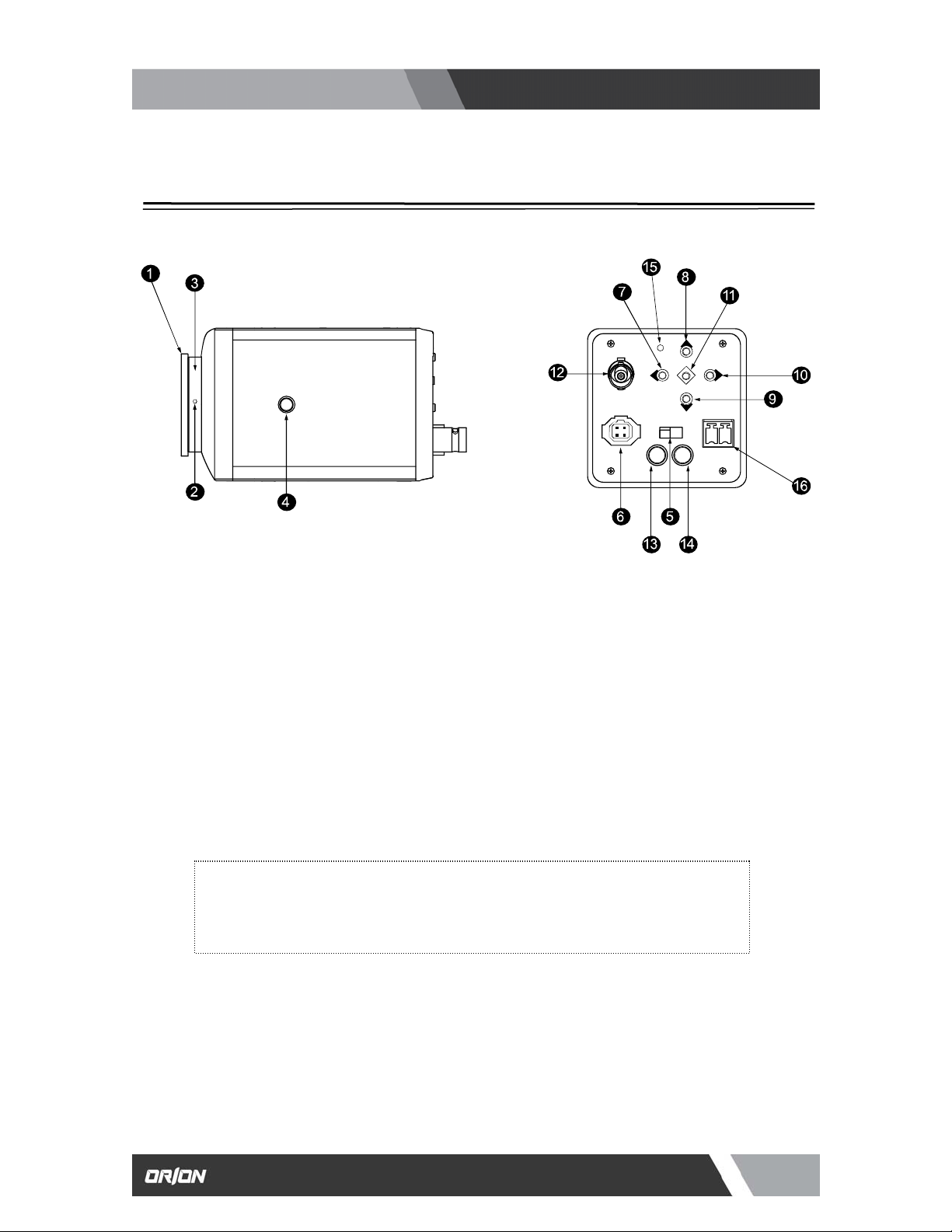
5. NAMES OF PARTS AND FUNCTIONS
Top View
① C-MOUNT RING
This can be removed when used with CS-Mount lens.
② LENS FLANGE BACK FOCUS SCREW
To be used to adjust the lens flange back focal distance (distance between lens mounting
edge and image focal point), if the camera fails to come into focus with the lens focus ring,
this can be used for re-adjustment of lens back focus using a hex driver attached.
LENS MOUNT
This is used to mount the lens on the camera. Many types of CS mount lens can be
.
CS MOUNT)
CAMERA MOUNT SCREW HOLES
These holes are used to install and fix the camera on the camera mounting or bracket.
Those can be also applicable to normal use tripods which have a quarter i nch thre ad. T his
mount located on the bottom and top of the camera.
NOTE:
To use these holes to attach the camera on a tripod or other mount, make sure you
use suitable size mounting bolts as follows (1/4” -20UNC), they should not be
longer than 5.5mm to avoid an un-stable installation.
LENS IRIS CONTROL SELECTOR SWITCH
The switch has two positions, for a video controlled auto-iris lens or a DC auto-iris lens.
AUTO IRIS LENS CONNECTOR
Specifically used to connect the auto iris lens.
Installation and User’s Guide
Rear View
6
7300 Bolsa Avenue, Westminster CA 92683 / Tel: 714-766-6300 / Fax: 714-766-6310
pg6
Page 7

http://www.orionimages.com
FOR THE VIDEO CONTROLLED TYPE AUTO IRIS LENS
Set the lens selector switch to VIDEO position.
-Connector cable leads -
① Red (power)
② Not used
③ White (video)
④ Black (shielded)
*Make proper isolation on the tip of the green wire to prevent a short-circuit.
FOR THE DC CONTROLLED TYPE AUTO IRIS LENS
Set the lens selector switch to DC position.
-Connector cable wires -
① Damping coil (-)
② Damping coil (+)
③ Driving coil (+)
④ Driving coil (-)
*Connect the wires as shown above.
Please refer also to the instruction of the lens to be used.
⑦-⑪ CAMERA SETUP FUNCTION SWITCHES
Please refer to the operation chapter.
⑫ VIDEO OUTPUT CONNECTOR (VIDEO OUT)
For HD-SDI output from camera. Connect this output to HDTV monitor or HDTV
switcher, etc. This to be terminated with 75 ohms impedance at the last equipment
in a loop when cascade / bridge loop connection is made.
⑬ NTSC / PAL OUTPUT
Use a mini-plug connector.
⑭ RS-232C
This is for data value adjustment.
⑮ POWER INDICATOR (POWER)
The LED indicator stays on in green while the camera power is on. This camera
does not have own power on/off switch. Utmost care should be paid when doing
repair or service work.
You may do wnload the camera control application from our website to control this
camera remotely.
16
DC12V POWER INPUT TERMINAL
For power, apply the input power of DC10 – 16V.
*This installation should be made by a qualified service person and should conform to all local codes.
Installation and User’s Guide
Auto iris lens
Auto iris lens
7
7300 Bolsa Avenue, Westminster CA 92683 / Tel: 714-766-6300 / Fax: 714-766-6310
pg7
Page 8

6
-
g
p
http://www.orionimages.com
Installation and User’s Guide
6. OPERATION
1. USER SETUP
The CHDC-21BSDC series camera has provision of camera setup and memory function for camera ID
setting, sync system selection, various picture quality setups, Back light compensation, Privacy Mask
setting, Day/Night, Motion Detection settings for optimum reproduction.
The SETUP can be easily executed using the On-Screen-Menu system. Alteration of these function ma y
be needed for some installations and we recommend that you should spend some time to become
acquainted with these functions so that the best results can be obtained from this high performance HD
CCTV camera.
6-2. SETUP SWITCHES AND FUNCTIONS
The push buttons and marked as the left are
provided on the rear panel on the camera.
Up Switch (U) To be used for a selection of SET UP parameters
Down Switch (D)
Right Switch (R)
Left Switch (L)
(up and down).
To be used to chan
e the settings.
Enter Switch (E)
*To enter the setup mode, hold down the E button longer than 1 seconds.
To be used to enter the setu
mode and to save the setup data.
8
7300 Bolsa Avenue, Westminster CA 92683 / Tel: 714-766-6300 / Fax: 714-766-6310
pg8
Page 9

(
p
r
http://www.orionimages.com
6-3. ENTERING THE SETUP MODE AND ITS BASICS
6-3-1. SETUP MENU (Main Menu)
Hold down the E button longer than 1 second, and the
menu at left appears on the left top of the screen and
press E button one more time to move the menu at the
center of screen.
A highlighted item is now selected.
(1) DISPLAY MODE :
This is to select the output signal including the
resolution format, the frame, CVBS aspect ratio and
the color bar.
z SDI SCALE
Classify the range of digital output signal.
FULL mode-
COMP mode-
z SDI FPS
This is to select the frame per second. When selected 1080p format, you can select 30 or 25.
When selected 720
z CVBS
This is to select an analog composite signal output format at mini- plug connector ⑬, NTSC o
format, you can select 60 or 50.
z SDI FORMAT
1080p-
720p-
SDI output for resolution is 1920 x 1080p
SDI output for resolution is 1280 x 720p
Installation and User’s Guide
SDI FULL Range Out (0 ~ 255), usually
applied on HDMI, DVI, IP (all signal
outputs)
SDI Normal Range Out (16 ~ 235),
(Black 16, White 235), usually applied on
SDI
Setup Level goes up to 7.5 IRE).
9
7300 Bolsa Avenue, Westminster CA 92683 / Tel: 714-766-6300 / Fax: 714-766-6310
pg9
Page 10

y (E)
(2)
y (E)
(3)
A
f
r
A
y (E)
http://www.orionimages.com
z CVBS-Ratio
Aspect ratio of NTSC or PAL can be selected in either 16:9 or 4:3.
z COLOR BAR
When it is turned ON, SMPTE COLOR BAR signal can be displaye d thru the video output
connector ⑫.
z SHADING DET
This is for shading correction. When you see the difference of illumination on the display area,
turn ON to start a scan and save when it’s completed.
z DEFECT DET
This is to compensate dead pixels of C-MOS sensor. Before running this DEFECT DET, AGC
value has to run at 3 or 4 LEVEL. After DEFECT DET IS ON, Press RIGHT key (R) to start a
z RETURN
Press ENTER ke
LENS :
z RETURN
Press ENTER ke
SHUTTER / AGC :
z DSS
This is for Digital Slow Shutter. You can select off, x2, x3 or x4 mode. Larger number causes in
brighter image, but slower the moving object.
z FREQ
Select 60Hz or 50Hz.
z RETURN
Press ENTER ke
to exit and return to previous menu.
Select DC / Video / manual lens iris.
z MODE
This has three positions:
DC-
For a DC auto iris lens
VIDEOMANUAL-
to exit and return to previous menu.
Select Auto/Manual Shutter and adjust AGC
z SHUTTER
UTO-
MANUAL-
z
GC
This is Auto Gain Control. Gain Level can be adjusted in
a range of 0 to 20.
to exit and return to previous menu.
For a video controlled auto iris
For a manual iris lens
To set in Auto Shutter Mode
To set manual shutter speed in the value o
1/30, 1/60, 1/120, 1/250, 1/700/ 1/1000,
1/1600, 1/2500, 1/5000, 1/7000, 1/10000, o
1/30000 sec when the object is moving fast,
select smaller value of the shutter speed to
capture the object clearly.
Installation and User’s Guide
10
7300 Bolsa Avenue, Westminster CA 92683 / Tel: 714-766-6300 / Fax: 714-766-6310
pg10
Page 11

(4)
A
y
j
A
y
http://www.orionimages.com
Installation and User’s Guide
AWB :
Select Auto or Manual / white balance.
z MODE
You can select AUTO, PRESET, or MANUAL.
UTO-
White Balance is automaticall
PRESETMANUAL- You can select a three color temperatures,
ctivate a data stored in manual mode..
Low (3700°K), Middle (5100°K) or High
(9500°K). Also R Gain and B Gain can be
usted in a range of 0 to 10.
ad
adjusted.
z COLOR TEMPERATURES IN DEGREES KELVIN
Color Temperature is the standard method
to describe characters of light and is
normally expressed in degrees Kelvin (K)
Large numbers show more bluish color. (Not
directly related Brightness)
2 hours from Dawn
1 hour from Dawn
Earl
Sunrises
Before and after Sunrise / Sunset
10000K
9000K
8000K
7000K
6000K
5000K
4000K
3000K
2000K
1000K
Clear Blue Sky
TV Screen
Over cast sky
Sun Light
White Fluorescent Lamp
Halogen Lamp
Incandescent Lamp
Sodium Lamp
Candle Light
11
7300 Bolsa Avenue, Westminster CA 92683 / Tel: 714-766-6300 / Fax: 714-766-6310
pg11
Page 12

(5)
http://www.orionimages.com
PICT ADJUST :
z FLIP
This function is to reverse the top and the bottom on the screen. This feature can be used for the
microscope application etc..
z STILL
This is to output a still image when turned ON.
z SHADING
This is to set ON when activates shading correction.
z D ZOOM
Pressing (R) button / increase zoom ratio (Maximum number 112 will be 8 times zoom).
z HL MASK
This is for the high light masking.
z RETURN
Press (E) button to go back previous menu.
Installation and User’s Guide
You can adjust the Brightness, the Contrast, the Color
Gain, Shading, Mirror, Flip, Still, Shading or Digital Zoom.
z BRIGHTNESS
Brightness can be adjusted in arrange of 0 to 20.
Pressing (R) button will make brighter.
z COLOR GAIN
Color Gain can be adjusted in a arrange of 0 to 20.
Pressing (R) button will add more color.
z ACE
This is ON/OFF selection of Annotated Critical
Evidence (ACE).
z SHARPNESS
Sharpness can be adjusted in a range of 0 to 20.
Pressing (R) button will make sharper image.
z MIRROR
This function is to reverse the left and right on the
screen. This feature can be used for the rear-view
vehicle application, etc.
12
7300 Bolsa Avenue, Westminster CA 92683 / Tel: 714-766-6300 / Fax: 714-766-6310
pg12
Page 13

(6)
(7)
A
f
f
A
http://www.orionimages.com
WDR / BLC / DNR :
z BLC POS-Y
This is to position the BLC area vertically. The setting of range is from 0 to 20.
z BLC SIZ-X
This is to increase the size of BLC area horizontally. The setting of range is from 0 to 20.
z BLC SIZ-Y
This is to increase the size of BLC area vertically. The setting of range is from 0 to 20.
z DNR (Digital Noise Reduction)
This can be selected In either LOW, MIDDLE or HIGH to reduce noise digitally.
z RETURN
Press (E) button to go back previous menu.
DAY & NIGHT :
AGC THRS:
MARGIN:
This is for AGC threshold. Set up
DAY & NIGHT boundary line o
current AGC setting level.
Set up range of Night threshold
and Day threshold standard o
GC THRS boundary line.
Installation and User’s Guide
Wide Dynamic (WDR) or Backlight Compensation (BLC) &
Digital Noise Reduction (DNR) level can be selected.
z MODE
This is to modify intensity of WDR and SDI out FFS goes
down to 15 from 30.
*Note: This function does not work for CVBS output. Also does
not operate on SHUTTER MANUAL MODE.
WDR_WGT
z
This is to increase the level of WDR from range of 0 to 4.
z BLC OSD
This is to activate the BLC position and BLC size.
z BLC POS-X
This is to position the BLC area horizontally. The setting
of range is from 0 to 20.
UTO / COLOR / B&W / OFF can be selected.
z MODE
When MODE is AUTO, the following menu is displayed.
13
7300 Bolsa Avenue, Westminster CA 92683 / Tel: 714-766-6300 / Fax: 714-766-6310
pg13
Page 14

(8)
)
(E)
http://www.orionimages.com
Installation and User’s Guide
DELAY:
RETURN:
Press
-
button to go back previous menu.
PRIVACY :
This is to set the area to be masked (not to view on the
screen). Up to 4 zones can be assigned
z MODE
When turn ON, the following can be displayed on the
screen.
z ZONE NO
You can se lect zone number 0 to 31. Left top is zone number 0, left right is zone
number 5.
z ZONE OP: ON
This is to keep or erase the zone number specified under ZONE NO.
For example, if you need to erase zone number 2, set ZONE NO as “2” then set
ZONE OP as “ON”.
z X-POS
This is to move the zone specifies under the ZONE NO horizontally (in a range from
0 to 60).
z Y-POS
This is to move the zone specifies under the ZONE NO vertically (in a range from 0
to 40).
z X-SIZ
This is to change a size of the ZONE specified in the ZONE NO horizontally (in a
range from 0 to 40).
z Y-SIZ
This is to change a size of the ZONE specified in the ZONE NO vertically (in a range
from 0 to 40
.
14
7300 Bolsa Avenue, Westminster CA 92683 / Tel: 714-766-6300 / Fax: 714-766-6310
pg14
Page 15

(9)
http://www.orionimages.com
z COLOR
This is to select the color of the ZONE to be marked;
CYN → Cyan
GRN → Green
MAG → Magenta
RED → Red
BLU → Blue
BLK → Black
WHT → White
YEL → Yellow
z TRANS
This is to select a transparency of the ZONE in a range of 0, 1, 2, 3, and 4.
z RETURN
Press (E) button to go back to previous menu.
MOTION DET :
Installation and User’s Guide
This is to set the area to be detected for the motion. Up yo
4 zones can be assigned with any size over the screen.
z RESOLUTION
This is for the level of resolution to detect a motion.
Level should be set 0 to 4 higher value to detect the
details.
z SENSITIVITY
This is for the level of sensitivity to detect a motion.
Level should be set 0 to 20. Higher value to detect
smaller moving.
z RETURN
Press (E) button to go back previous menu..
15
7300 Bolsa Avenue, Westminster CA 92683 / Tel: 714-766-6300 / Fax: 714-766-6310
pg15
Page 16

(10)
(11)
(E)
http://www.orionimages.com
Installation and User’s Guide
CAMERA ID :
z SET UP ID
You can set your each camera ID by entering name.
z RETURN
Press (E) button to go back to previous menu.
SYSTEM INFO :
(12) RESET :
This activates all settings go back to factory original value.
This is to add the camera ID on the screen.
z MODE
Turn ON to add the camera ID.
z X-POS
This is to move the zone specifies under the ZONE
NO vertically (in a range from 0 to 40).
z Y-POS
This is to move the zone specifies under the ZONE
NO vertically (in a range from 0 to 40).
z VERSION
0.0.3.
z DATE
2011 / 6 / 24
z RETURN
Press
button to go back previous menu.
16
7300 Bolsa Avenue, Westminster CA 92683 / Tel: 714-766-6300 / Fax: 714-766-6310
pg16
Page 17

http://www.orionimages.com
7. SPECIFICATIONS
CHDC-21BSDC
Image Sensor 1/3” CMOS
Effective Pixel 1944(H) x 1092(V), 2.1M Pixel
Sync System Internal
Video Output
Minimum Illumination 0.1 Lux (F1.2, 50 IRE, AGC Max)
Auto White Balance Auto / Manual
Backlight Compensation Built-In
Noise Reduction Built-In
Installation and User’s Guide
HD-SDI (SMPTE 274M) / 75 ohm BNC x 1
1920 x 1080 30p / 25p, 1280 x 720 60p / 50p
NTSC / PAL 1Vp-p / 75 ohm Mini-Plug x 1
4:3 or 16:9 Selectable
Color Bar Signal
Electric Shutter
Auto IRIS Function DC or Video Selectable
Day & Night Built-In
Mirror Image DC or (Horizontal and Vertical)
Privacy Mask Function Built-In
Motion Detection Built-In
Camera ID Built-In
Lens Mount CS Mount (C Mount Ring is provided as standard)
Power Requirement DC 12V (Voltage Tolerance: 10V ~ 16V) 190Ma ~ 10%
Power Consumption Max 2.3W
Operating Temperature
Operating Humidity 20 ~ 80%
Camera Mount 1/4” ~ 20UNC x 2 (Top and Bottom)
Dimensions (W x H x D) 2.32” x 2.32” x 4.02”
Weight 0.55 lbs
Auto / Manual (Manual: 1/30, 1/60, 1/120, 1/250, 1/700, 1/1000,
1/1600, 1/2500, 1/5000, 1/7000, 1/10000, 1/30000 sec)
32° ~ 122° F (0° ~ 50° C)
* Design and specifications are subject to change without notice
17
7300 Bolsa Avenue, Westminster CA 92683 / Tel: 714-766-6300 / Fax: 714-766-6310
pg17
Page 18

http://www.orionimages.com
8. OUTLINE DIMENSION
Side View
Top View
Installation and User’s Guide
Unit: Inch
Rear View
Front View
18
7300 Bolsa Avenue, Westminster CA 92683 / Tel: 714-766-6300 / Fax: 714-766-6310
pg18
Page 19

http://www.orionimages.com
Installation and User’s Guide
9. WARRANTY & AFTER-SALE SERVICE
Warranty accompanies this product. Read and fill out the warranty card that you have
received at your dealer. Keep this card in a safe place.
z Please consult ORION Images Corporation or your dealer for full warranty information. Your dealer
will repair or replace free of charge within the warranty period according to the warranty coverage.
z For repairs after the expiration of the warranty period, consult your dealer or sales representative. It
will first be judged whether the fault is repairable or not. Charged servicing will then be made upo n
request of the user.
z Before you ask for servicing, please ensure you read the instruction Manua l. If the unit still fails,
take note of the model number, date of purchase, problem, etc. In detail, and inform your dealer or
sales representative.
z If you have questions about the after-sale service, contact your dealer or sales representative.
* We suggest you ask for preventive inspection as soon as possible.
Contact ORION Images :
In the event of missing and/or damage equipment, or technical questions, the following
information can help in the completion of the installation.
Address: 7300 Bolsa Avenue, Westminster, CA 92683
Tel: 714-766-6300 / Fax: 714-766-6310
Email: sales@orionimages.com
Website: http://www.orionimages.com
19
7300 Bolsa Avenue, Westminster CA 92683 / Tel: 714-766-6300 / Fax: 714-766-6310
pg19
 Loading...