

Page 1

LIMITED TWO MONTH CONSUMER WARRANTY AND ONE YEAR CO NS UM ER WA RR AN TY
WHE N PURC HAS ED AND INSTALLED F ROM AUTHO RIZED ORION D EALER
Electronics Limited Warranty
Please keep your original bo x. Orion wa rr an ts th is produc t t o b e f re e fr om defec ts in ma te ri als and wo rk ma ns hi p
under normal use for a pe riod of TWO (2) mont hs f rom th e dat e of origi nal purc hase rece ipt . When
purchased and installed from an AUTHORIZ ED OR IO N d ea ler i t i s w ar ra nt ed for a pe ri od of ON E (1 ) Year f ro m
the date of the or ig inal pur ch as e r ec ei pt.
The ORIGINAL Receipt m us t b e provid ed fo r all c la ims. Sho ul d s er vi ce be nece ss ar y u nd er this warr an ty fo r a ny
reason due to manufacturing de fe ct or mal fu nc ti on du ring the w ar ra nt y p eriod.
ORION will repair or replace (at its di sc re ti on ) t he defec ti ve mer ch andise w it h e qu iv al ent merc ha nd is e w it h
equivalent merchandise at no ch ar ge. Warr an ty re pl ac ements m ay ha ve co sm etic scra tc he s o r b lemishe s.
Discontinued products may be re pl aced wit h m or e c ur re nt equiva le nt pr od uc ts.
This warranty is valid o nl y t o t he origina l purc ha se r a nd is non -t ra ns fe rable to any ot he r person or par ty . A ny
applicable implied warranties are limited i n d ur at io n t o a per iod of th e e xp re ss warrant y p ro vi de d h erein
beginning with the date of the original pu rc ha se at retail, an d no wa rr an ties, wh et he r e xp re ss or implie d,
shall apply to this pr od uct ther ea ft er . S om e states do not al low limi ta ti on s o n im plied wa rr an ti es ; t herefor e
these exclusions may not ap pl y to you. Th is warranty gi ve s y ou sp ecific l eg al rig ht s; ho wever yo u m ay hav e
other rights that vary fr om state to st at e.
What to Do if you need Warranty or Service
Defective merchandise should be r et ur ne d to your lo ca l auth or ized ORI ON de al er fo r warran ty ser vi ce .
Assista nc e l oc at in g an a ut ho ri ze d dealer ca n b e f ou nd at the p ro du ct s m ai n website ww w. or io nc araudio .c om
or by contacting ORION di re ctly at 1 -8 55 -4 75 -6 048.If i t b ec om es necessa ry fo r yo u to retu rn DE FE CT IV E
merchandise directly to ORION, ca ll the ORIO N C us to me r Care nu mb er at 1- 85 5-475-6 04 8 fo r a Return
Merchandise Authorization (RMA) nu mb er. Pack ag e a ll def ective ite ms in th e or iginal c on ta in er or in a packa ge
that wil l p re ve nt sh ipping dama ge . T he shippin g a dd re ss and instructions will be given to yo u by our cust om er
care representative upon their i ss ui ng the RMA numb er .
The RMA number must be cl ea rl y m ar ked on the ou ts id e o f th e packag e. Pl ea se return only de fe ct iv e compon ents. The return of f un ctionin g i te ms in cr eases yo ur ret ur n f reight c ha rg es . N ON - DE FECTIVE it em s w il l n ot be
exchanged.You will be conta ct ed by cu st omer care ad vi si ng yo u of such sit ua ti on s, an d produc t will be re turned
to you upon your pa ym ent of fr ei gh t c ha rg es for t he re tu rn of such prod uc t b ac k t o yo u.
Include a c op y o f th e o riginal re ce ip t w ith th e PURCHA SE DATE clearly visible, and a ROOF of PURCHASE
statement listing the CUSTOMERS NAME, DE AL ER 's NA ME and INVOI CE nu mb er , a nd prod uc t p ur ch ased.
Warranty expiration on i te ms without ROOF of PURCHASE wil l be deter min ed from the typ e of s ale
and manu fa ct ur in g d ate code . FREI GH T o n d ef ectives pr od uc ts re turned must be PR EPAID by you or y ou r
authorized dealer; items sent fr ei ght coll ec t, or CO D will be R EF US ED .
What is not covered?
The warranty is valid on ly if the pr od uc t is us ed for the purp os e f or wh ich it w as de si gn ed and does NOT CO VE R
the foll ow in g;
Damage due to improper in st allatio n a nd so un d s ettings , exce ss iv e o r insuff ic ie nt vo ltage spike s,
and use of inferior lo w g rade wir in g.
Subsequent Damage to other co mp onents
Damage c au se d b y e xp osure to moist ur e, ex ce ss ive heat , chem ic al cl eaners, an d/ or UV Rad ia ti on.
Damage t hr ou gh ne gl igence, mi su se , acci de nt or abuse . R ep ea te d re turns fo r t he sa me da mage may b e
con sid ered a bus e.
Any cost or ex pe ns e rela ted to th e r em ov al or i nstalla ti on of pr od uct. No In st al la ti on Fee re im bu rs em en ts.
Items pr ev io us ly re paired o r modi fi ed by an y unauth or iz ed rep air faci li ty
Return s hi pp in g c os ts from ORIO N t o y ou on non -defect iv e i te ms
Product s w it h t am pe red or missi ng ba rc od e l abels
Product s r et ur ne d w ithout a Ret ur n M er ch an dise Aut ho ri za ti on (RMA ) n um be r
Fre igh t Dama ge
The cost of sh ip pi ng pro du ct to ORI ON , f ro m yo u t o Orion
Service pe rf or me d b y anyone other th an Or io n
Damage r el at ed to Acts of Nature, lightning, hur ri ca nes, flo od , t or na do es, and wild fi re s.
Product s S ol d o ut si de of United St at es ha ve NO WARRANTY ex pr es se d o r impli ed
How long will it ta ke ?
ORION strives to maintain a g oa l of 7 day s er vi ce fo r a ll electron ic s p ro du ct s (ampli fi er s, eq ualizer s , ele ct ro ni c
crossovers, etc.) returns. Delays may be incurred if lac k of repl ac em en t i nventory or pa rt s i s e nc ountere d.
Failure to follow these Steps may void you r w ar ra nt y. Any questions ca n b e d ir ec ted to the OR IO N C us to mer
Care Department at 1-855-475-6048.
4 CHANNEL AM PL IFIER S
CB600.4
CB1000.4
CB1500.4
CB2000.4
CB3000.4
2 CHANNEL AM PL IFIER S
CB300.2
CB600.2
CB1200.2
CB2700.2
5 CHANNEL AM PL IFIER S
CB1500.5
CB2700.5
MONOBLOCK CLASS AB 2 OHM AMPLI FIERS
CB1000.1M2
MONOBLOCK CLASS D 1 O HM AMPLIFIERS
CB1000.1D
CB1500.1D
CB2500.1D
CB3500.1D
CB5000.1D
MONOBLOCK CLASS D 2 O HM AMPLIFIERS
CB1500.1D2
CB2500.1D2
2016
Page 2

TABLE OF CONTENTS
Introduction................................................................................. .......2
Installation Instructions...................................................................... .2
Record Your Serial Number and Date.................................................... 2
Functions....................................................................................... 3~4
Operation ...........................................................................................5
Trouble Shooting.......................................................................... ...... 5
Precautions ........................................................................................6
Fuse Replacement.............................................................................. 6
Stereo Mode .................................................................................7~9
Speakers Connections..................................................................10~17
Bridged Mode.............................................................................. 18~20
Speaker Connections At Bridged...................................................21
Power Connection Leads................................................................... 27
Wiring Instructions............................................................................ 28
Operation .........................................................................................29
Interference ......................................................................................30
Specification ...............................................................................31~35
~26
INTRODUCTION
Thank you for purc hasing ou r car audi o am plifi er. The se pow er ampli fier has b een
designed to provide high q uality pe rformanc e wi th min imu m
maintenance. However, it' s perform ance will onl y be as goo d as the care a nd
quality of components wi th w hich i s insta lled. We there fore advi se that you re ad
these instructions very ca ref ully t o fa milia riz e yo ursel f wi th the pro duct and i t's
features.
Before installing the p owe r ampl ifi er ple ase rea d this ins truct ion manual ca refully.
The instructions for mo unt ing an d co nnect ing the set ha ve t o be follo wed precisel y.
If neces sary, a service cente r should b e co nsulted.
All connection for DC powe r, s ignal inp ut and spe ake r outp uts can be car rie d out
easily and safely by wa y of RCA and screw ed termin als.
INSTALLATION INSTRUCTIONS
Please choose a mount ing place without a ny d irect wea ther infl uences. N ote that
the amplifier generates h eat so tha t a well venti lat ed place i s necessa ry.
According to your c ar' s cons tru ction the set can be mad e very car efully in ord er to
ensure the amplifier's f ull perfo rma nce an d relia bilit y.
Keep the wire connect ions as sh ort as pos sib le wit h sufficient length in
order to minimize pow er l osses and pro vide a hig her audio out put of the system.
For safety reasons rout e al l powe r and sp eaker wir ing by usi ng t he exitin g wire
channels.
To mi nimize da mage to the ca bles, tak e ca re tha t th ey do not p ass sharp edg ed
metal.
Lay all cables as far aw ay a s poss ibl e from the ign ition cab les, modu les in the
boot and under the key dashboar d, a s thes e cr eate inte rfe rence .
Add a fuse into th e (+) powe r ca ble in a di sta nce of not mor e than 30c m from the
positive battery pole.
Keep the length of the p ower wire s as short as p oss ible . It i s be tter to us e power
cables which are shor t and then lon ger sp eak er cab les .
In order to redu ce interf erence , p lea se pay att entio n to the wirin g instructio ns.
RECORD YOUR SERIAL NUMBER AND DATE
To en sure y our warra nty, p lea se rec ord th e fo llowi ng inf orm ation regar din g
your new amplifier.
Model:
Seri al Number :
Date of Purcha se:
Purc hased fro m:
1
2
Page 3

FUNCTIONS
FUNCTIONS
CB600.4/CB1000.4 /CB1500.4/CB2000.4 /CB3000 .4
PWR
PRO
REMOTE
BASS BOOST
0dB +10dB
40Hz 500Hz
INPUT MODE
LO
50Hz
HPFMODELPF
OUTPUT
HI
4KHz
CH3
CH3
GAIN
Max
Min
FULL
HPF
LPF
CH4
INPUT
CH2
CH1CH4
INPUT MODE
LO
50Hz
4KHz
BASS BOOST
GAIN
0dB +10dB
Max
HI
Min
FULL
HPF
LPF
40Hz 500Hz
MODEHPF
LPF
CB300.2/CB600.2/ CB1200.2
LINE INP UT
LINE OUTPWR
PRO
R
L
LO HI
Max
0dB +10d B
Min
BASS B OOST
GAININPUT MO DE
HPF LPF
FULL
50Hz
4KHz
HPF MODE LP F REMO TE
40Hz 5 00Hz
CB1500.5 / CB2700.5
CB2700.2
LINE INPU T
LINE OUT
PWR
PRO
R
LO HI
INPUT MOD E
L
0dB +18 dB
Max
Min
BASS BO OST
GAIN
HPF LPF
50Hz
HPF
40Hz 500H z
4KHz
FULL
MODE
0
0
180
0
PHASE
LPF
CB1000.1M2
LINE OUT
LINE INPUT
R
L
MIN MAX
GAIN
O
O
180
0
25HzOFF
PHASESUB SONIC
15Hz 0dB
400Hz
BASS BOOST
LPF
+18dB
REMOTE
PWR
PRO
CB1000.1D/CB1500 .1D/CB1500.1D2/CB2 500.1D/
CB2500.1D2/CB350 0.1D/CB5000.1D
PWR
PWR
PRO
PRO
PRO
LINE OUT
LINE INPUT
R
Max
Min
GAIN
L
O
O
180
0
25HzOFF
PHASESUB SONIC
15Hz 0dB
400Hz
BASS BOOST
LPF
+18dB
REMOTE
IN
OUT
REMOT E
BRIDGED
CH3/CH4
FULL
HPF
MODE
50Hz
4KHz
HPF
50Hz
4KHz
HPF MODE GAIN INPUT MODE
FULL
CH1/CH2
Max
Min
Max
Min
INPUT
LO
HI
LO
HI
CH4CH2
CH1 CH3
INPUT MODE
GAIN
PWR
R
LO
CH5
HI
L
400Hz 15Hz
LPF
Min
+18dB
0dB
BASS BOOST
CH5
PRO
Max
REMOTE
3
Input Mode
Gain control
LPF / HPF contr ol
Mosfet power supply
1~5 Channel Power Amplifier
Sub Sonic control
Bass Boost control
Thermal protection
LED Power and Prote cti on Indicator
Low Input and High Inp ut S elected
4
Page 4

OPERATION
PRECAUTIONS
GND(-)=GROUND CONNECTION
Connect the GND te rminal to the cha ssis grou nd of your c ar and take care o f best
electric and mechanic co ntact. In doing s o, drill a hole in to the car c hassis near
the amplifier then re move colo r, d irt or any other subs tance fro m the gr oun d poin t.
After that fasten th e cabl e en d with a dded ring termin al b y usin g a screw. Ensure
that the ground co nnection is as short as pos sible a nd t hat th e cable dia meter is
sufficient ( min 4 mm" ) . Route the ground cab les fr om t he radio and al l oth er
equipment parts. like eq ualizer. active cross ove r netw ork or ot her am pli fiers , to
the same ground po int.
+12V=POWER SUPPLY
Connect the +12V te rminal to the positive p ole of t he batter y with a lea d cabl e
and add a fu se in t o the power cable i n a d istan ce of not mo re then 30 c m from t he
battery. The lea d cables' s diame ter shoul d be at leas t 4 mm' for a length of 3 m
and 6 mm" fo r a len gth of 6m.
REM(ON/OFF)REMOTE CONTROL
Connect the REM te rminal to the aut omatic an tenna con nector of y our ca r rad io.
Now when turning on and off your car radio . the ampl ifier a uto matic all y swit che s
ON and OFF. A cab le dia met er of 0. 5mm is suf ficient.
FUSE
The amplifier is eq uipped wi th a plu g-i n auto fus e prote cti ng the set agains t fa ult
conditions. Do not us e a fuse wit h a hig her value a nd n ever bridg e the f use over ,
as this may le ad to i rre parab ili ty damage s o that ant any c laim for wa rra nty is
denied.
TROUBLE SHOOTING
No Function:
The connection cable is not conne cted correctly ( = terminal BATT/GND /REM).
Ensure that all con nections and mecha nic contac t and that the jac ket has bee n
removed. The fuse is defecti ve-pay at tention to the corre ct valu e of a new fu se!
No Sound:
Speaker cable or sp eaker plu g are not connect ed correc tly.
No Sound /Red LE D Prot ect ion Sh ine s:
The plus and mi nus wires of the spea ker cable have co nta ct, th us el imina te t he
short circuit. If yo u use a 2 Ohm spe aker in ste reo mode, a 4 Ohm speak er in
bridge mode or tr i-mode an d the se is overloaded, then tu rn the gai n contr ol t o
"min " until th e oper ati on is free of trou ble.
Poor Sound Quality ( D istor tio ns ):
The speakers are ov erloaded , therefo re turn dow n th e volu me level and ch eck
the volume control po sitions.
No Stereo Sound An d A Weak Ba ss:
Speaker cables (+) an d (-) are mixed up , un it w ire d out of phase.
t
This unit is desi gned for n egative g rou nd 12V DC o per ation onl y.
Use speakers with an im pedance o f 2 o r 4 O hms ( 2 to 4 Ohm wh en used as
brid gin g ampl ifi er )
Avoid installing the u nit where :
-It would be subj ect to hig h temperatur es, such a s from direct sunlight or h ot air
from the heater.
-It would be expo sed to rai n or moisture .
-It would be subj ect to dus t or dirt.
If your car is pa rked in direc t sunligh t and there is a consi derab le r ise in
temperature inside the car, allow the uni t to cool off before op eration.
When installing the unit horizont ally, be sure not to cov er t he hea tsi nk fin s with
the floor carpet.
If this unit is pl aced too clos e to the car ra dio, an inter fer ence m ay o ccur. In this
case, separate the ampl ifier fro m the car radi o.
This power amplifier empl oys a prot ection circu it to prot ect the trans istors an d
speakers if the ampl ifier m lfunctions. Do not attem pt to test the protecti on
circuits by covering the h eatsink o r connecting improper loads.
Do not use the u nit with a wea k auto b atter y as its optim um p erfor man ce
depends on a norm al batter y supply volt age.
For safety reasons, keep the volum e of your car audi o system m oderate so th at
you can still hear normal tr affic sounds outside yo ur car .
a
FUSE REPLACEMENT
If the fuse blow s, check t he p ower c onn ectio n an d re place the f us e. If t he f use
blows again after repl acement, there may be a n inte rna l ma lfunc tio n. In t his case,
consult your dealer.
WARNING:
Use the specified ampe rage fuse . Use of a high er a mpera ge f use may cause
serious damage.
PROTECTION CIRCUIT:
This amplifier is prov ided with a pr otection circuit w hich oper ate s in th e follo wing
cases when:
the unit is o verhe ate d.
the spea ker termi nals are s hor t circ uit ed.
5
6
Page 5

STEREO MODE
STEREO MODE
CB600.4/CB1000.4 /CB1500.4/CB2000.4 /CB3000 .4
PWR
PRO
REMOTE
BASS BOOST
0dB +10dB
40Hz 500Hz
CH4
GAIN
INPUT MODE
Max
Min
FULL
HPF
LPF
50Hz
OUTPUT
LO
HI
4KHz
HPFMODELPF
CH3
CH3
INPUT
CH2
CH1CH4
CH1 CH2CH4 CH3
GAIN
INPUT MODE
LO
Min
HI
FULL
HPF
50Hz
4KHz
MODEHPF
CAR STEREO
Max
LPF
BASS BOOST
0dB +10dB
40Hz 500Hz
CB300.2/CB600.2/ CB1200.2
LINE INP UT
LINE OUTPWR
PRO
R
Max
0dB +10 dB
Min
LO HI
L
GAININP UT MODE
BASS B OOST
L
R
HPF LP F
FULL
50Hz
4KHz
HPF MODE LP F REMO TE
40Hz 500H z
CAR STEREO
CB2700.2
LINE INPU T
LINE OUT
PWR
PRO
R
LO HI
INPUT MOD E
L
0dB +18 dB
Max
Min
BASS BO OST
GAIN
HPF LPF
50Hz
HPF
40Hz 500H z
4KHz
FULL
MODE
0
0
180
0
PHASE
LPF
REMOT E
L
LPF
R
CAR STEREO
CB1500.5/2700.5
CH3/CH4
FULL
HPF
MODE
50Hz
4KHz
FULL
HPF
50Hz
4KHz
HPF MODE GAIN INPUT M ODE
CH1/CH2
LO
HI
Max
Min
LO
Max
Min
HI
Input Mode
Gain control
LPF / HPF control
Mosfet power supply
1~5 Channel Power Amplifier
Remote control
Bass Boost control
Thermal protection
LED Power and Protection Indic ato r
Low Input
INPUT
CH1 CH3
CH4CH2
CH3 CH4CH2 CH1 CH5
INPUT MODE
R
LO
CH5
L R
HI
L
400Hz 15Hz
LPF
CAR STEREO
GAIN
Max
Min
+18dB
0dB
BASS BOOST
CH5
PWR
PRO
REMOTE
7
8
Page 6

STEREO MODE
SPEAKERS CONNECTIONS
CB1000.1M2
LINE OUT
LINE INPUT
R
R
MIN MAX
L
GAIN
25HzOFF
0
PHASESUB SONIC
O
180
O
15Hz 0dB
LPF
400Hz
BASS BOOST
+18dB
REMOTE
L
CAR STEREO
PWR
PRO
CB1000.1D/CB1500 .1D/CB1500.1D2/CB2 500.1D/
CB2500.1D2/CB350 0.1D/CB5000.1D
LINE OUT
LINE INPUT
R
25HzOFF
Max
Min
GAIN
L
PHASESUB SONIC
O
0
O
180
15Hz 0dB
400Hz
BASS BOOST
LPF
+18dB
REMOTE
PWR
PWR
PRO
PRO
PRO
CB600.4/CB1000.4
Ch1
SPEAKER
2~4Ohm
Ch3
SPEAKER
2~4Ohm
SPEAKER OU TPUT
CH1 CH2
CH3 CH4
BRIDGED
Ch2
SPEAKER
2~4Ohm
FUSES
Ch4
SPEAKER
2~4Ohm
REM GND
+12V
POWER INPUT
CB600 .4 :30Ax 2
CB100 0. 4:35A x2
CB1500.4/CB2000. 4
IN
BRIDGED
OUT
Ch1
SPEAKER
2~4Ohm
SPEAKER OU TPUT
CH1 CH2
Ch2
SPEAKER
2~4Ohm
FUSES
+12V
REM GND
L
R
9
CAR STEREO
Ch3
SPEAKER
2~4Ohm
CH3 CH4
BRIDGED
10
Ch4
SPEAKER
2~4Ohm
POWER INPUT
CB150 0. 4:30A x3
CB200 0. 4:35A x3
Page 7

SPEAKERS CONNECTIONS
SPEAKERS CONNECTIONS
CB3000.4
Ch1
SPEAKER
2~4Ohm
Ch3
SPEAKER
2~4Ohm
CB300.2
LEFT
SPEAKER
2~4Ohm
SPEAKER OU TPUT
CH3 CH4
CH1 CH2
BRIDGED
Ch2
SPEAKER
2~4Ohm
Ch4
SPEAKER
2~4Ohm
RIGHT
SPEAKER
2~4Ohm
REM GND
+12V
POWER INPUT
CB3000.4:150A
CB600.2/CB1200.2
LEFT
SPEAKER
2~4Ohm
LEFT RIGHT
SPEAKER OUTPUT
CB2700.2
BRIDGED
CB600 .2 :30Ax 2
CB120 0. 2:40A x2
L
SPEAKER
2~4Ohm
RIGHT
SPEAKER
2~4Ohm
FUSES
REM
+12V
POWER INPUT
GND
R
SPEAKER
2~4Ohm
BRIDGED
LEFT RIGHT
SPEAKER OUTPUT
FUSE
30A
11
REM
+12V
POWER INPUT
GND
GND
REM
+12V
POWER INPUT
BRIDGED
LEFT RIGHT
SPEAKER OUTPUT
CB2700.2:150A
12
Page 8

SPEAKERS CONNECTIONS SPEAKERS CONNECTIONS
CB1500.5
CB2700.5
CB1500.5:100A
CB1000.1M2
MONO S PE AK ER
2~4Ohm
+ +
SPEAKER OUTPUT
CB1000.1D
MONO S PE AK ER
1~4Ohm
+ +
SPEAKER OUTPUT
MIN 2
MIN 1
FUSES
30A X 3
40A X 2
FUSES
REM+12V
POWER INPUT
REM GND
+12V
POWER IN PUT
GND
GND
REM
+12V
POWER INPUT
CB2700.5:150A
CB1500.1D
MONO S PE AK ER
CH5
SPEAKER OUTPUT
MIN 1
CH1 CH2
CH3 CH4
BRIDGED
SPEAKER OUTPUT
1~4Ohm
+ +
SPEAKER OUTPUT
MIN 1
13 14
FUSES
40A X 3
REM GND
+12V
POWER IN PUT
Page 9
SPEAKERS CONNECTIONS SPEAKERS CONNECTIONS
CB2500.1D
MONO SPEAKER
SPEAKER OUTPUT
CB3500.1D
MONO S PE AK ER
1~4Ohm
+ +
MIN 1
1~4Ohm
+ +
FUSES
30A X 4
REM GND
+12V
POWER IN PUT
CB5000.1D
CB1500.1D2
MONO S PE AK ER
2~4Ohm
+ +
MONO S PE AK ER
2~4Ohm
+ +
GND
REM
+12V
SPEAKER OUTPUT
POWER INPUT
CB5000.1D:250A
SPEAKER OUTPUT
MIN 1
FUSES
40A X 5
15
REM GND
+12V
POWER IN PUT
SPEAKER OUTPUT
MIN 2
FUSES
40A X 3
16
REM GND
+12V
POWER I NPU T
Page 10

SPEAKERS CONNECTIONS
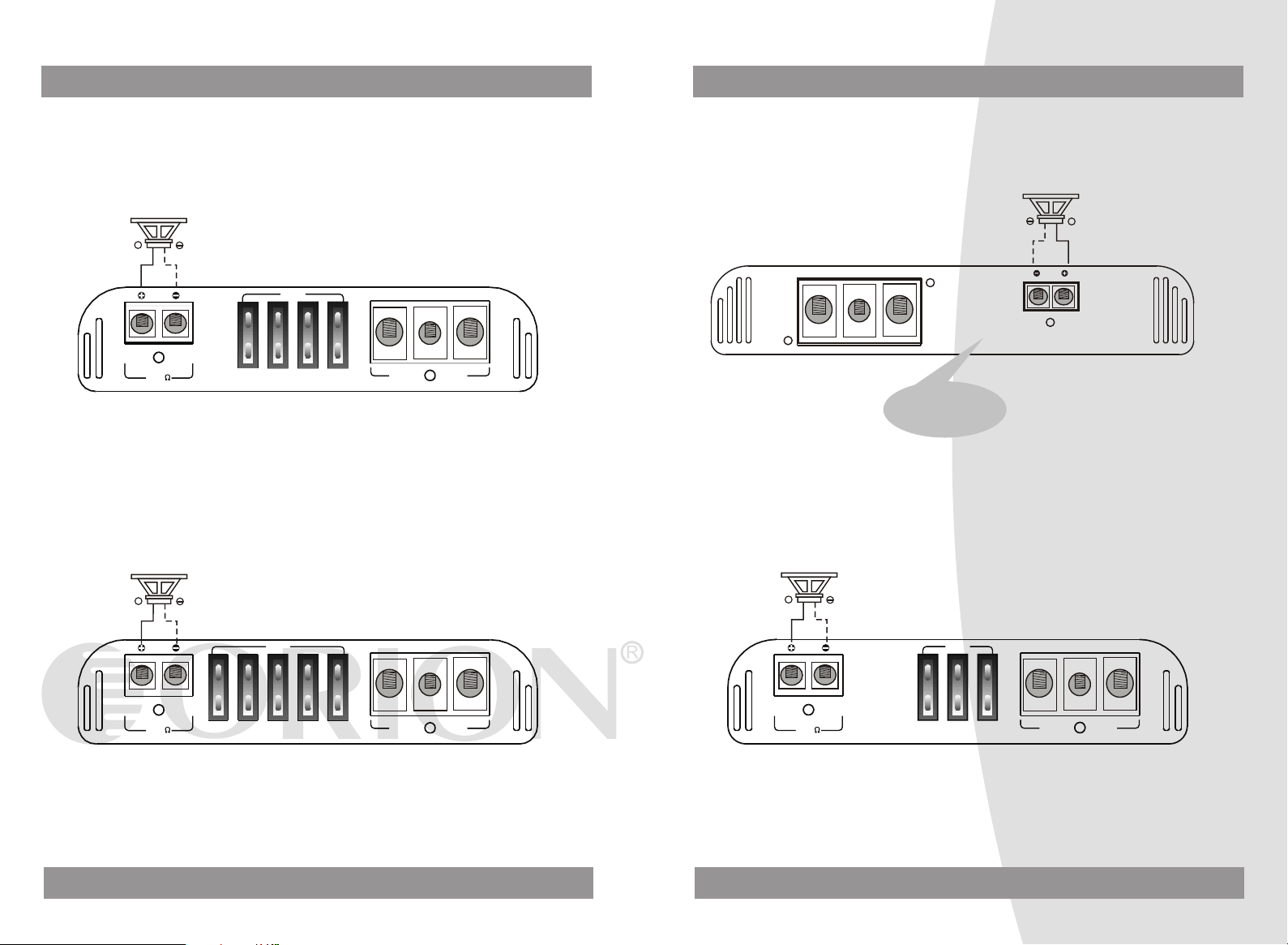
BRIDGED MODE
CB2500.1D2
MONO S PE AK ER
2~4Ohm
+ +
SPEAKER OUTPUT
MIN 2
CB600.4/CB1000.4
MONO SPEAKER
4~8Ohm
FUSES
30A X 4
REM GND
+12V
POWER IN PUT
CB1500.4/CB2000. 4
MONO SPEAKER
4~8Ohm
CH1 CH2
SPEAKER OU TPUT
CH3 CH4
BRIDGED
MONO SPEAKER
4~8Ohm
CB3000.4
FUSES
CB150 0. 4:30A x3
CB200 0. 4:35A x3
MONO SPEAKER
4~8Ohm
REM GND
+12V
POWER INPUT
SPEAKER OUT PUT
CH1 CH2
CH3 CH4
BRIDGED
MONO SPEAKER
4~8Ohm
FUSES
CB600 .4 :3 0A x2
CB100 0. 4: 35 Ax2
17
REM GND
+12V
POWER INPUT
CH1 CH2
SPEAKER OU TPUT
CH3 CH4
BRIDGED
MONO SPEAKER
4~8Ohm
18
REM GND
+12V
POWER INPUT
CB3000.4:150A
Page 11

BRIDGED MODE BRIDGED MODE
CB300.2
MONO SPEAKER
4~8Ohm
BRIDGED
LEFT RIGHT
SPEAKER OUTPUT
CB600.2/CB1200.2
MONO SPEAKER
4~8Ohm
BRIDGED
LEFT RIGHT
SPEAKER OUTPUT
FUSE
30A
FUSES
REM
+12V
POWER INPUT
REM
+12V
POWER INPUT
GND
GND
CB1500.5
CB2700.5
MONO SPEAKER
4~8Ohm
MONO SPEAKER
4~8Ohm
CB1500.5:100A
MONO SPEAKER
4~8Ohm
CB2700.2
CB600 .2 :30Ax 2
CB120 0. 2:40A x2
GND
REM
+12V
POWER INPUT
MONO SPEAKER
4~8Ohm
BRIDGED
LEFT RIGHT
SPEAKER OUTPUT
GND
REM
+12V
POWER INPUT
CH5
SPEAKER OUTPUT
MIN 1
CH1 CH2
CH3 CH4
BRIDGED
SPEAKER OUTPUT
CB2700.5:150A
MONO SPEAKER
4~8Ohm
CB2700.2:150A
19
20
Page 12

SPEAKERS CONNECTIONS AT BRIDGED SPEAKERS CONNECTIONS AT BRIDGED
CB1000.1D/CB1500 .1D/CB2500.1D/CB35 00.1D
AMP 1
SPEAKER OUTPUT
2~8Oh m
MIN 1
FUSES
30A X 5
CB1 000.1 D:40A x2
CB1 500.1 D:40A x3
CB2 500.1 D:30A x4
CB3 500.1 D:40A x5
BATTERY
DC 12V
REM GND
+12V
POWER IN PUT
To a metal
part of car
CB1000.1D/CB1500 .1D/CB2500.1D/CB35 00.1D
AMP 1 MASTER
LINE OUT
LINE INPUT
R
25HzOFF
Max
Min
GAIN
L
PHASESUB SONIC
O
0
O
180
15Hz 0dB
400Hz
BASS BOOST
LPF
+18dB
PWR
PWR
PRO
PRO
PRO
CAR STEREO
IN
BRIDGED
REMOTE
OUT
AMP 2
SPEAKER OUTPUT
MIN 1
CB1 000.1 D:40A x2
CB1 500.1 D:40A x3
CB2 500.1 D:30A x4
CB3 500.1 D:40A x5
FUSES
30A X 5
REM GND
+12V
POWER IN PUT
AMP 2
SAVEL
PWR
PWR
PRO
PRO
PRO
LINE OUT
LINE INPUT
R
25HzOFF
Max
Min
GAIN
L
21 22
PHASESUB SONIC
O
0
O
180
15Hz 0dB
400Hz
BASS BOOST
LPF
+18dB
IN
BRIDGED
REMOTE
OUT
Page 13

SPEAKERS CONNECTIONS AT BRIDGED SPEAKERS CONNECTIONS AT BRIDGED
CB5000.1D
AMP 1 MASTER
LINE OUT
PWR
PRO
LINE INPUT
SUB SONIC
GAIN
R
Max
25Hz
Min
OFF
L
CAR STEREO
PHASE
O
0
CB5000.1D
AMP 1
BASS BOOST
LPF
O
+18dB
400Hz 15Hz
0dB
180
REMOTE
IN
BRIDG ED
OUT
GND
REM
+12V
SPEAKER OUTPUT
POWER INPUT
CB5000.1D:250A
To a metal
part of car
BATTERY
DC 12V
4~8 Ohm
AMP 2 S AVEL
AMP 2
GND
REM
LINE INPUT
LINE OUT
PWR
PRO
SUB SONIC
PHASE
GAIN
R
Max
25Hz
Min
OFF
L
BASS BOOST
LPF
O
O
180
0
+18dB
400Hz 15Hz
0dB
REMOTE
IN
BRIDG ED
OUT
POWER INPUT
23
+12V
SPEAKER OUTPUT
CB5000.1D:250A
24
Page 14

SPEAKERS CONNECTIONS AT BRIDGED SPEAKERS CONNECTIONS AT BRIDGED
CB1500.1D2/CB250 0.1D2 CB1500.1D2/CB250 0.1D2
AMP 1
SPEAKER OUTPUT
4~8Oh m
AMP 2
MIN 2
FUSES
CB150 0. 1D2:4 0A x3
CB250 0. 1D2:3 0A x4
CB150 0. 1D2:4 0A x3
CB250 0. 1D2:3 0A x4
BATTERY
DC 12V
REM GND
+12V
POWER IN PUT
To a metal
part of car
AMP 1
AMP 2
MASTER
PWR
PWR
LINE OUT
PRO
PRO
PRO
CAR STEREO
SAVEL
LINE INPUT
IN
R
25HzOFF
Max
Min
GAIN
L
PHASESUB SONIC
O
0
O
180
15Hz 0dB
400Hz
BASS BOOST
LPF
+18dB
REMOTE
BRIDGED
OUT
SPEAKER OUTPUT
MIN 2
FUSES
25
REM GND
+12V
POWER IN PUT
PWR
PWR
PRO
PRO
PRO
LINE OUT
LINE INPUT
IN
R
25HzOFF
Max
Min
GAIN
L
PHASESUB SONIC
O
0
O
180
15Hz 0dB
400Hz
BASS BOOST
LPF
+18dB
REMOTE
BRIDGED
OUT
26
Page 15

POWER CONNECTION LEADS
POWER
HEAD UNIT
REM
+12V
( +12V)
REMOTE OUT
FUSE
++
BATTERY
GND
DC 12V
to a metal part of car
NOTES ON THE POWER SUPPLY :
Connect the +12V po wer input lea d on ly aft er a ll o ther l ead s have bee n
connected.
Be sure to conn ect the gr ound wire of t he u nit se cur ely to a me tal part of th e car.
A lose con nection m ay cause a mal funct ion of t he amp lif ier.
REM: The unit is turned on b y applyin g +1 2 Volts to thi s termina l. T his te rmi nal
does not draw heav y cu rrent lik e th e Powe r Terminals s o a thi nne r
connecting wire is a cce ptabl e. S tandard 1 8 GA UGE is fin e and the s tandard
color is yellow .lf t he radio i s eq uippe d wi th a Power Antenna control wire, it can
drive this terminal . If t he P ower A nte nna wire i s al ready in u se, you can st ill
splice into it. W ith this m eth od, the un it w ill turn o n au tomat ica lly with t he radio.
Use the power supp ly lead wi th a fuse a tta ched whos e va lue is the same as
original fuse.
Place the fuse i n th e power suppl y lead as c los e as po ssi ble to the car battery .
During a full powe r operati on, maxim um c urren t wi ll run thr ough the s ystem
Therefore, make sure t hat th e le ads to be c onn ected to t he +12V and GN D
termina ls of the u nit respe cti vely m ust be larger than 10-Gaug e ( AWG.10).
WIRING INSTRUCTIONS
POWER CONNECTION
The battery terminal (+12 V) m ust be con nected di rectly to the positive terminal of
the vehicle battery to pr ovi de an adeq uate volt age sourc e and minimiz e noise.
Connecting the battery term ina l lead to a ny other p oint (such as the fuse bloc k )
will reduce the powe r ou tput a nd m ay cause n oise and dist ortion. U se o nly #1 0
gauge or thicker (sma lle r gaug e # ) wire for this lead and conn ect it to the t erminal
of the battery afte r all othe r wiring is co mpleted.
GROUND CONNECTION
The ground terminal (GND ) co nnect ion is a lso criti cal to the cor rect oper ation o f
the amplifier. Use a wire o f the s ame gau ge as the powe r connect ion ( #1 0 or thicker)and connect it betw een the gr oun d te rminal (G ND ) of the amp lifier and a
metal pa rt of the vehi cle close to t he m ounti ng loca tion. Thi s wire sh ould be as
short as possible and a ny p aint or rust a t the groundi ng point shou ld b e scra ped
away to provide a cle an m etal surf ace to whi ch the e nd of th e grou nd w ire can be
screwed or bolted .
REMOTE TURN-ON CONNECTION
The amplifier is turn ed o n by apply ing +12V t o the re mote turn -on ter minal (RE M).
The wire lead to th is termin al s hou ld be c onn ected to the " Auto-Ant enna " l ead
from the car ster eo which w ill pro vide t he + 12V only when the car stere o is tur ned
on. If the car s tereo doe s not pr ovide an Auto -Antenna " lead, the re mot e turn -on
lead may be wire d to an " Acces sor y " or "Radio " terminal in t he c ar's f use blo ck.
This will turn the a mplifier on a nd o ff with the ign ition k ey, regardles s of wheth er
the car stereo is on or o ff. The rem ote turn- on l ead does not c arry la rge cu rre nts.
So #20 gauge wire m ay be us ed for thi s applicatio n.
SPEAKER CONNECTIONS
Depending on the type and numbe r of spe akers use d with the amp lifier, wire them
to the speaker termin als as per the app ropriate wiring diagr am. For mo st
applications #18gauge wire shoul d be used for the s peaker leads but in n o case
thinner than #20 gaug e. F or lea ds in ex cess of 10 fee t # 1 6 ga uge is recomm ended. When wiring the s pea kers, pay car eful atte ntion to the p olarity o f the te rminals on the spea kers and m ake cer tain t hey corre spo nd t o the pola rity of the corresponding terminals on the a mpl ifier . Do not ground any sp eak er lea ds to th e
chassis of the vehic le.
INPUT CONNECTIONS
This amplifier features low- lev el inp ut c apabi lit y.
If the car ster eo does no t provi de low -le vel ou tpu ts, the ampli fier may be co nne c
-ted via the speak er (high- level) ou tputs f rom the st ereo with a AUTOCRAFT line
converter.
27
28
Page 16

OPERATION
After the amplifier has be en ins tal led and all connecti ons have be en m ade carefu l
-lyand securely, turn the radio on so that t he a mplif ier is switche d on automa tic ally.
After a short power -on pe rio d, the ampl ifier rea ches its full p erforman ce.
Now turn up the vo lume s low ly using th e volume contr ol of t he radio. If th ere is no
sound or only a dist orted rep lay, switch off the ra dio immed iat ely, the amplifier wil l
also switch off automat ically, and check if al l conn ect ions h ave been made c orrectly.
POWER=LED POWER INDICATOR
After the orderly conne ction of t he three po wer termi nals, the L ED i ndica tor shines
green and goes out wi th off .
PROTECT =LED PROTECTION INDICATOR
This set is e quipp ed w ith an overloa d protect ion, imme diately upon o verloadi ng
due to short circu it or m uch increased temperat ure the ove rlo ad pro tec tion i s
activated and the red LE D indi cat or is shi ning. Thr ough this t he amp lif ier is
protected against damage. In cas e of the the rmal prot ection a ce rta in sho rt cooling
time must be allow ed aft er w hich the am plifier a utomatic ally resum es o perat ion .
LEVEL CONTROL
The input level contr ol all ows the system to work wel l wi thin a wide range of outpu t
level. Choose the adjus tment in t he way that you achiev e a s ound m ost possib ly
without any distortion. as a gu ideli ne the followi ng proced ure is re comme nde d:
If you use sever al amp lif ier, the adjustm ent has to b e ma de for each set separatel y,
tune up the volum e of yo ur car radio to 2/3 o f the maxim um volume .
Now turn the gain c ontro l of the amplif ier from " Min " to " Max " dire ction unt il you
can hear distortions. Then t urn th e le vel con trol a lit tle back to " Min ". T he gain
control adjustment is finis hed no w.
Attention! If you use 2 Ohm spe akers in st ere o mode . Tri -mode or 4 Ohm spe akers
in bridge mode and th e over loa d protecti on is trig gered, tur n the gain control t o
" Min " direc tion, unt il the oper ation is f ree of trou ble.
HIGH PASS AND LOW PASS CONTROLS
This amplifier has controls for making good s ound
combination.
high pass and low pa ss
INTERFERENCE
All cables are sour ces of int erferenc e. T he pow er cable and RC A aud io c able
are very prone to in terferen ce; the remot e cabl es a re less pr one . There is ofte n
interference caused by t he g enera tor (pipi ng) , ig nitio n ( c racki ng ) or other car
electronic parts. Most o f th ese pr obl ems can be eli minat ed b y correct and careful
cabling. In doing so, t hese are t he f ollow ing guide lin es :
Use only a scre ened audi o cable for th e wiri ng b etw een " l ow l eve l in " of th e
amplifi er and RCA o r DI N outp ut o f th e radi o .
Lay the signal, speak er and pow er c ables sep arate ly w ith enoug h distanc e
from one another a nd a lso fr om e ach other car cab le. lf not possible , you can
lay the circuit and gro und ca ble tog ether wit h the seri al c ables . Audio and
speaker cable should b e as far away f rom these as p oss ible. The REM cable to
the automatic antenna o utp ut of t he r adi o can b e laid t ogeth er w ith the si gnal
cables.
Avoid ground loop s by layin g the ground w iring of all c omponent s to a cent er
point in a star -like way. You can find th e best cen tral point in measurin g th e
voltage directly at t he b atter y. Now compare this vo ltage val ue w ith th e ch osen
ground point and the ( +) termin al o f the a mpl ifier. lf the meas ure d volt age in
only less different you've found the c orr ect ce ntr al.Other wise you h ave to loo k
for another point. Y ou shou ld measur e with the ign ition bei ng s witch ed o n and
additionally switched on o the r elec tro nics ( rea r wi ndow h eat ing and li ght ).
If there are pi cku ps from ex ternal elect rical sou rces i nto the speak er cables ,
divide the core lead s and twis t th em tog eth er.
If there are no ise s from the car elect ron ics. Add an interference s uppressi on
choke to the powe r wiring .
If there are hum ing noises, u se t hicke r gr ound c abl es or add f urther groun d
cables to the chas sis.
To re duce cont act resis tance and bad and loose con tacts , pl ease tin t he cable
ends or use multi c ore cable end s, spa de t ermin als or others . Go ld Plated
spade terminal are fre e of corrosio n an d have the low est co nta ct res ist ance.
Should all these measur es to with out any su cce ss. th e use of a ground l oop
isolato r may solv e th e prob lem .
29
30
Page 17

SPECIFICATION
SPECIFICATION
POWER DESCRIPTION
RMS Watts @ 4 O hm
Stereo 14.4V
RMS Watts @ 2 O hm
Stereo 14.4V
RMS Watts @ 4 O hm
Bridge 14.4V
Watts Nominal
Max Music Power W at ts
Frequency Response
Signal Noise Ratio
Input Impedance
Input Sensitivity
T.H.D.
Hi Pass Freq.
Low Pass Freq.
Bass Boost
Supply Voltage
Dimensions(mm)
FOUR CHANNEL
CB600.4
60 X 4
80 X 4
160 X 2
600 1000
1200 2000
10Hz~36KHz(-3dB)
90dB
22K Ohm
250mV~5V
<0.05%
50Hz-4KHz
40Hz-500Hz
0~+10dB
11~15V DC
354x190x50 374x190x50
CB1000.4
85 X 4
125 X 4
250 X 2
10Hz~36KHz(-3dB)
90dB
22K Ohm
250mV~5V
<0.05%
50Hz-4KHz
40Hz-500Hz
0~+10dB
11~15V DC
POWER DESCRIPTION
RMS Watts @ 4 O hm
Stereo 14.4V
RMS Watts @ 2 O hm
Stereo 14.4V
RMS Watts @ 4 O hm
Bridge 14.4V
Watts Nominal
Max Music Power W at ts
Frequency Response
Signal Noise Ratio
Input Impedance
Input Sensitivity
T.H.D.
Hi Pass Freq.
Low Pass Freq.
Bass Boost
Supply Voltage
Dimensions(mm)
FOUR CHANNEL
CB1500.4
115 X 4
185 X 4
375 X 2
1500
3000
10Hz~36KHz(-3dB)
90dB
22K Ohm
250mV~5V
<0.05%
50Hz-4KHz
40Hz-500Hz
0~+10dB
11~15V DC
414x190x50
TWO CHANNEL
CB300.2
60 X 2
80 X 2
160
300
600 1200
10Hz~36KHz(-3dB)
90dB
22K Ohm
250mV~5V
<0.05%
50Hz-4KHz
40Hz-500Hz
0~+10dB
11~15V DC
274x190x50 284x190x50
CB600.2
110 X 2
160 X 2
320
600
10Hz~36KHz(-3dB)
90dB
22K Ohm
250mV~5V
<0.05%
50Hz-4KHz
40Hz-500Hz
0~+10dB
11~15V DC
CB2000.4
150 X 4
250 X 4
500 X 2
2000
4000
10Hz~36KHz(-3dB)
90dB
22K Ohm
250mV~5V
<0.05%
50Hz-4KHz
40Hz-500Hz
0~+10dB
11~15V DC
514x190x50
CB1200.2
200 X 2
300 X 2
600
1200
2400
10Hz~36KHz(-3dB)
90dB
22K Ohm
250mV~5V
<0.05%
50Hz-4KHz
40Hz-500Hz
0~+10dB
11~15V DC
354x190x50
CB3000.4
250 X 4
375 X 4
750 X 2
3000
6000
10Hz~36KHz(-3dB)
90dB
22K Ohm
250mV~5V
<0.05%
50Hz-4KHz
40Hz-500Hz
0~+10dB
11~15V DC
540x190x50
CB2700.2
450 X 2
675 X 2
1350
2700
5400
10Hz~36KHz(-3dB)
90dB
22K Ohm
250mV~5V
<0.05%
50Hz-4KHz
40Hz-500Hz
0~+18dB
11~15V DC
558x250x55
31
32
Page 18

SPECIFICATION
SPECIFICATION
POWER DESCRIPTION
RMS Watts @ 4 O hm
Stereo 14.4V
RMS Watts @ 2 O hm
Stereo 14.4V
RMS Watts @ 4 O hm
Bridge 14.4V
Frequency Response
Signal Noise Ratio
Input Impedance
Input Sensitivity
T.H.D.
Hi pass Freq.
RMS Watts @ 4 O hm
Mono 14.4V
RMS Watts @ 2 O hm
Mono 14.4V
RMS Watts @ 1 O hm
Mono 14.4V
Class D Section W at ts Nominal
Total A mp lifier W at ts Nomina l
Max Music Power W at ts
Frequency Response
Signal Noise Ratio
Input Impedance
Input Sensitivity
T.H.D.
Low pass Freq.
Bass Boost
Supply Voltage
Dimensions(mm)
FIVE CHANNEL
CB1500.5
75 X4
100 X 4
200 X 2
10Hz~36KHz(-3dB)
90dB
22K Ohm
250mV~5V
<0.05%
50Hz-4KHz
200
375
N/A
700
1500
3000
10Hz~400Hz(-3dB)
90dB
22K Ohm
150mV~5V
<0.05%
15Hz-400Hz
0~+18dB
11~15V DC
474x190x50
CB2700.5
100 X4
160 X 4
320 X 2
10Hz~36KHz(-3dB)
90dB
22K Ohm
250mV~5V
<0.05%
50Hz-4KHz
250
375
700
1400
2700
5400
10Hz~400Hz(-3dB)
90dB
22K Ohm
150mV~5V
<0.05%
15Hz-400Hz
0~+18dB
11~15V DC
508x250x55
CLASS AB MONO 2 O HM C HANNE L S TABLE 2 OHM
POWER DESCRIPTION
RMS Watts @ 4 O hm
Mono 14.4V
RMS Watts @ 2 O hm
Mono 14.4V
Watts Nominal
Max Musi c P ow er Wat ts
Frequency Response
Signal Noise Ratio
Input Impedance
Input Sensitivity
T.H.D.
Subsonic
Low Pass Freq.
Phase
Bass Boost
Supply Voltage
Dimensions(mm)
CLASS D MONO 1 O HM CHANN EL
POWER DESCRIPTION
RMS Watts @ 4 O hm
Mono 14.4V
RMS Watts @ 2 O hm
Mono 14.4V
RMS Watts @ 1 O hm
Mono 14.4V
Watts Nominal
Max Music Power W at ts
Frequency Response
Signal Noise Ratio
Input Impedance
Input Sensitivity
T.H.D.
Subsonic
Low Pass Freq.
Bass Boost
Phase
Supply Voltage
Dimensions(mm)
CB1000.1D
240
325
500
1000
2000
10Hz~400Hz(-3dB)
90dB
22K Ohm
150mV~5V
<0.05%
25Hz
15Hz-400Hz
0~+18dB
O O
0 / 180
11~15V DC
307x190x50
CB1000.1M2
325
500
1000
2000
10Hz~400Hz(-3dB)
90dB
22K Ohm
150mV~5V
<0.05%
25Hz
15Hz-400Hz
O O
0 / 180
0~+18dB
11~15V DC
334x190x50
CB1500.1D
275
360
750
1500
3000
10Hz~400Hz(-3dB)
90dB
22K Ohm
150mV~5V
<0.05%
25Hz
15Hz-400Hz
0~+18dB
O O
0 / 180
11~15V DC
344x190x50
33
34
Page 19

SPECIFICATION
CLASS D MONO 1 O HM CHANN EL
POWER DESCRIPTION
RMS Watts @ 4 O hm
Mono 14.4V
RMS Watts @ 2 O hm
Mono 14.4V
RMS Watts @ 1 O hm
Mono 14.4V
Watts Nominal
Max Music Power W at ts
Frequency Response
Signal Noise Ratio
Input Impedance
Input Sensitivity
T.H.D.
Subsonic
Low Pass Freq.
Phase
Bass Boost
Supply Voltage
Dimensions(mm)
POWER DESCRIPTION
RMS Watts @ 4 O hm
Mono 14.4V
RMS Watts @ 2 O hm
Mono 14.4V
RMS Watts @ 1 O hm
Mono 14.4V
Watts Nominal
Max Music Power W at ts
Frequency Response
Signal Noise Ratio
Input Impedance
Input Sensitivity
T.H.D.
Subsonic
Low Pass Freq.
Phase
Bass Boost
Supply Voltage
Dimensions(mm)
10Hz~400Hz(-3dB)
CLASS D MONO 2 O HM CHANN EL
CB2500.1D
425
860
1250
2500
5000
90dB
22K Ohm
150mV~5V
<0.05%
25Hz
15Hz-400Hz
O O
0 / 180
0~+18dB
11~15V DC
379x190x50
CB3500.1D CB5000.1D
10Hz~400Hz(-3dB)
22K Ohm
150mV~5V
<0.05%
15Hz-400Hz
0 / 180
0~+18dB
11~15V DC
399x190x50
CB1500.1D2
420
750
N/A
1500
3000
10Hz~400Hz(-3dB)
90dB
22K Ohm
150mV~5V
<0.05%
25Hz
15Hz-400Hz
O O
0 / 180
0~+18dB
11~15V DC
344x190x50
880
1360
1750
3500
7000
90dB
25Hz
O O
1200
1800
2500
5000
10000
10Hz~400Hz(-3dB)
90dB
22K Ohm
150mV~5V
<0.05%
25Hz
15Hz-400Hz
O O
0 / 180
0~+18dB
11~15V DC
528x250x55
CB2500.1D2
650
1250
N/A
2500
5000
10Hz~400Hz(-3dB)
90dB
22K Ohm
150mV~5V
<0.05%
25Hz
15Hz-400Hz
O O
0 / 180
0~+18dB
11~15V DC
379x190x50
35
 Loading...