

Page 1

Installation and Operating Manual
Enhanced Model 2xx
Software v3.x
Magnetostrictive
Level Transmitter
SIL 2
Page 2

Read this Manual Before Installing
his manual provides information on the Jupiter
T
®
agne-
m
tostrictive transmitter. It is important that all instructions
are read carefully and followed in sequence. Detailed
instructions are included in the Installation section of this
manual.
Conventions Used in this Manual
Certain conventions are used in this manual to convey
specific types of information. General technical material,
support data, and safety information are presented in
narrative form. The following styles are used for notes,
cautions, and warnings.
Notice of Trademark, Copyright, and Limitations
rion & Orion logotype, Magnetrol & Magnetrol
O
logotype, and Jupiter are registered trademarks of
Magnetrol International.
Copyright © 2010 Magnetrol International.
All rights reserved.
Performance specifications are effective with date of issue
and are subject to change without notice. Magnetrol
reserves the right to make changes to the product
described in this manual at any time without notice.
Magnetrol makes no warranty with respect to the accuracy
of the information in this manual.
NOTES
Notes contain information that augments or clarifies
an operating step. Notes do not normally contain
actions. They follow the procedural steps to which
they refer.
Cautions
Cautions alert the technician to special conditions that
could injure personnel, damage equipment, or reduce
a component’s mechanical integrity. Cautions are also
used to alert the technician to unsafe practices or the
need for special protective equipment or specific
materials. In this manual, a caution box indicates a
potentially hazardous situation which, if not avoided,
may result in minor or moderate injury.
WARNINGS
Warnings identify potentially dangerous situations or
serious hazards. In this manual, a warning indicates an
imminently hazardous situation which, if not avoided,
could result in serious injury or death.
Safety Messages
Follow all standard industry procedures for servicing electrical equipment when working with or around high
voltage. Always shut off the power supply before touching any components.
WARNING! Explosion hazard. Do not connect or dis-
connect equipment unless power has been switched off or
the area is known to be non-hazardous.
Low Voltage Directive
For use in Installation Category II, Pollution Degree 2. If
equipment is used in a manner not specified by the manufacturer, protection provided by the equipment may be
impaired.
Warranty
All Magnetrol/Orion electronic level and flow controls
are warranted free of defects in materials or workmanship
for one full year from the date of original factory shipment.
If returned within the warranty period; and, upon factory
inspection of the control, the cause of the claim is
determined to be covered under the warranty; then,
Magnetrol/Orion will repair or replace the control at no
cost to the purchaser (or owner) other than transportation.
Specific to the Jupiter line of products; warranty will be
void should the electronics housing or threaded fittings be
rotated. Rotating the electronics enclosure could cause
damage to the sensor cables.
Magnetrol/Orion shall not be liable for misapplication,
labor claims, direct or consequential damage or expense
arising from the installation or use of equipment. There
are no other warranties expressed or implied, except special written warranties covering some Magnetrol/Orion
products.
Quality Assurance
The quality assurance system in place at Magnetrol guarantees the highest level of quality throughout the company. Magnetrol is committed to providing full customer
satisfaction both in quality products and quality service.
Magnetrol’s quality assurance system is
registered to ISO 9001 affirming its
commitment to known international
quality standards providing the
strongest assurance of product/service
quality available.
46-648 Jupiter Magnetostrictive Transmitters
Page 3

Enhanced Jupiter®Magnetostrictive Transmitter
Table of Contents
1.0 Installation .....................................................................4
1.1 Unpacking ................................................................4
1.2 Electrostatic Discharge (ESD) Handling Procedure...4
1.3 Before You Begin.......................................................5
1.3.1 Site Preparation..............................................5
1.3.2 Equipment and Tools .....................................5
1.3.3 Operational Considerations............................6
1.3.4 Configuration Information.............................6
1.4 Mounting..................................................................6
1.4.1 External..........................................................6
1.4.2 Internal, Direct Insertion................................7
1.5 Wiring ......................................................................8
1.6 Configuring the Transmitter......................................9
1.6.1 Operating Parameters.....................................9
1.6.2 Transmitter Display and Keypad ....................9
1.6.3 Password Protection .......................................9
1.6.4 Menu: Step-By-Step Procedure.....................10
1.6.4.1 Measurement Type: Level Only.............11
1.6.4.2 Measurement Type: Interface Only .......13
1.6.4.3 Measurement Type: Interface & Level ...15
1.6.4.4 Measurement Type: Level & Interface ...17
1.7 Configuration Using HART®..................................19
1.7.1 Connections .................................................19
1.7.2 HART Display Menu...................................19
1.7.3 HART Revision Table ..................................19
1.7.4 HART Menu................................................20
UNDATION
1.8 FO
1.8.1 Description ...................................................21
1.8.2 Benefits .........................................................22
1.8.3 Device Descriptions ......................................22
1.8.4 Intrinsically Safe............................................23
2.0 Reference Information..................................................24
2.1 Description .............................................................24
2.2 Theory of Operation...............................................24
2.3 Troubleshooting ......................................................25
2.3.1 Troubleshooting ...........................................25
2.3.2 Status Messages ............................................26
2.3.3 Troubleshooting Flowcharts..........................27
2.4 Agency ....................................................................30
2.4.1 Agency Drawing...........................................30
2.4.2 Agency Specifications (Explosion Proof) ......32
2.4.3 Agency Specifications (ATEX)......................32
2.5 Maintenance ...........................................................32
2.5.1 Keep Control Clean .....................................32
2.6 Replacement Parts...................................................33
2.6.1 Parts Identification .......................................33
2.7 Specifications ..........................................................34
2.7.1 Performance .................................................34
2.7.2 Functional....................................................35
2.7.3 Physical ........................................................35
Glossary .........................................................................37
Configuration Data Sheet .............................................39
Fieldbus®Digital Communications ...21
46-648 Jupiter Magnetostrictive Transmitters
Page 4

1.0 Installation
aution: If equipment is used in a manner not specified by manu-
C
facturer, protection provided by equipment may be
impaired
This section provides detailed procedures for properly
installing, wiring, configuring and, if needed, troubleshooting the Jupiter magnetostrictive level transmitter.
In most cases externally mounted units will be shipped
from the factory attached to the Orion Instruments
magnetic level indicator.
1.1 Unpacking
Caution: Do not rotate the Jupiter electronics enclosure or any
threaded fittings. Rotating the electronics enclosure will
void warranty and could cause damage to sensor cables.
Unpack the instrument carefully. Inspect all units for
damage. Report any concealed damage to carrier within
24 hours. Check the contents against the packing slip and
purchase order. Check and record the serial number for
future reference when ordering parts.
Caution: Do not discard the shipping container until all parts are
accounted for and inspected.
1.2 Electrostatic Discharge (ESD) Handling Procedure
Magnetrol/Orion’s electronic instruments are manufactured to the highest quality standards. These instruments
use electronic components that may be damaged by static
electricity present in most work environments.
The following steps are recommended to reduce the risk of
component failure due to electrostatic discharge.
• Ship and store circuit boards in anti-static bags. If an antistatic bag is not available, wrap the board in aluminum
foil. Do not place boards on foam packing materials.
• Use a grounding wrist strap when installing and removing
circuit boards. A grounded workstation is recommended.
• Handle circuit boards only by the edges. Do not touch
components or connector pins.
• Make sure that all electrical connections are completely
made and none are partial or floating. Ground all equipment to a good, earth ground.
4
46-648 Jupiter Magnetostrictive Transmitters
Page 5

1.3 Before You Begin
Caution: This instrument is intended for use in Installation
ategory II, Pollution Degree 2 locations.
C
1.3.1 Site Preparation
Each Jupiter magnetostrictive transmitter is built to match
the specifications required within the defined model
option number. Wiring terminations will need to be made
and the configuration will need to be accomplished.
Ensure that the power to be supplied to the instrument is
the same voltage (24 VDC) as ordered with the instrument, and that the wiring between the power supply and
the Jupiter transmitter is correct for the type of installation. See Specifications, Section 2.7.
NOTE: Applying incorrect voltage will damage the unit.
When installing the Jupiter transmitter in a general
purpose or hazardous area, all local, state, and federal
regulations and guidelines must be observed. See Wiring,
Section 1.5.
1.3.2 Equipment and Tools
For installation of a new Jupiter with magnetic level indicator set, refer to Orion Instruments instruction manual
46-638.
To attach a Jupiter transmitter to an existing MLI or direct
insertion model, you may need the following tools:
5
⁄16" Nut-Driver (for tightening the mounting clamps).
•
• Screwdriver and assorted hand tools for making conduit
and electrical connections.
• Tape measure or ruler if configuring via Set 4 mA and
Set 20 mA display screens.
• Digital multimeter or DVM to troubleshoot supply
voltage problems.
46-648 Jupiter Magnetostrictive Transmitters
5
Page 6
1.3.3 Operational Considerations
Exterior ambient temperature of the service should not
exceed the design specifications of the electronics (-40° to
+175° F (-40° to +80° C)). The operating temperature
limits of the LCD are -5° to +160° F (-20° to +70° C).
Temperatures below -5° F will cause the display to temporarily white out, and temperatures above +160° F will
cause the display to go temporarily black. It will recover
without damage when the operating temperature range
returns. A sunshade should be used if electronics are
mounted in direct sunlight.
Maximum process temperature for direct insertion
transmitters is +500° F (+260° C). Externally mounted
transmitters can be used with process temperatures up
to +850° F (+455° C) if the MLI is equipped with an
insulation blanket from the factory.
1.3.4 Configuration Information
Some key information is needed to configure the Jupiter
transmitter. Complete the following operating parameters
table before beginning configuration.
Display Question Answer
Units What units of measurement will be
used? (inches or centimeters) _____________
Probe What probe length is listed on the
Length model information? _____________
Set What is the 0% reference point for the
4.0 mA 4.0 mA value? _____________
Set What is the 100% reference point for
20.0 mA the 20.0 mA value? _____________
1.4 Mounting
1.4.1 External
Caution: Do not rotate the Jupiter electronics enclosure or any
threaded fittings. Rotating the electronics enclosure will
void warranty and could cause damage to sensor cables.
If ordered from the factory with the MLI, the transmitter
will be attached to the gauge and configured for the measuring range specified at the time of order placement. If
not, use the following directions:
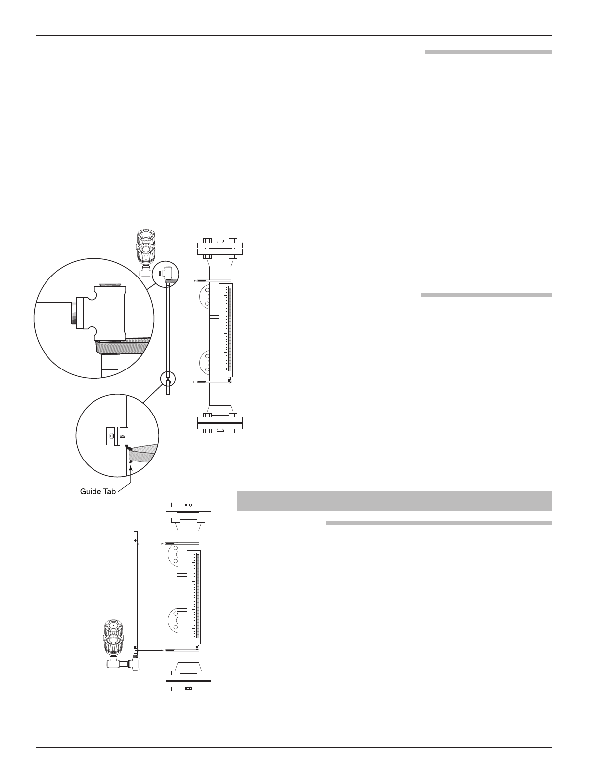
1. Place the Jupiter transmitter and mounting clamps in a
convenient location.
2. Position the Jupiter transmitter on the side of the MLI
where it will be attached. Mark the location and the exact
Figure 1
Mounting External Jupiter
6
area where the clamps will be attached to hold the Jupiter
in place.
46-648 Jupiter Magnetostrictive Transmitters
Page 7
3. Attach the lower clamp and tighten so that it remains in
Bottom view
Up
Upper Clamp
place, but loose enough so that there is still room to place
the guide tab from the Jupiter between the inside of the
clamp and the outer diameter of the MLI chamber. See
Figure 1.
4. The upper clamp will need to be open to a large enough
diameter to be able to mount to the MLI as well as the
probe. The upper clamp should be positioned just above
3
⁄4" NPT threads. See Figure 2.
the
5. Mount the Jupiter guide pin in the lower clamp and tighten.
If necessary, use strapping tape to temporarily hold in
place on the MLI. See Figure 1.
6. Position the upper clamp to attach the unit to the MLI
and tighten. See Figure 1.
7. Discard any tape temporarily holding the Jupiter to the
MLI.
1.4.2 Internal, Direct Insertion
Figure 2
Figure 3
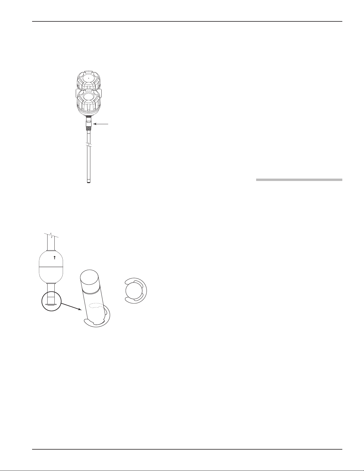
Float Attachment Detail
Use caution when handling probes to ensure probe is not
bent during installation. A bend in the probe may prevent
float from traveling freely up and down the probe.
Caution: Do not rotate the Jupiter electronics enclosure or any
threaded fittings. Rotating the electronics enclosure will
void warranty and could cause damage to sensor cables.
NOTE: Direct Insertion models may be calibrated prior to installation
by positioning the float at the desired 4 mA & 20 mA points.
See Section 1.6 for calibration details.
1. Verify float will pass through vessel opening, if not, it will
be necessary to attach the float after the probe is installed.
2. Carefully insert probe into vessel and thread or bolt to the
mating connection as appropriate.
3. The float is held on the probe by a C-clip inserted into a
groove machined into the tip of the probe. The float is
attached or removed by removing and reinserting the
C-clip. See figure 3. To ensure proper float orientation, the
float is marked “Up ”.
©
46-648 Jupiter Magnetostrictive Transmitters
7
Page 8
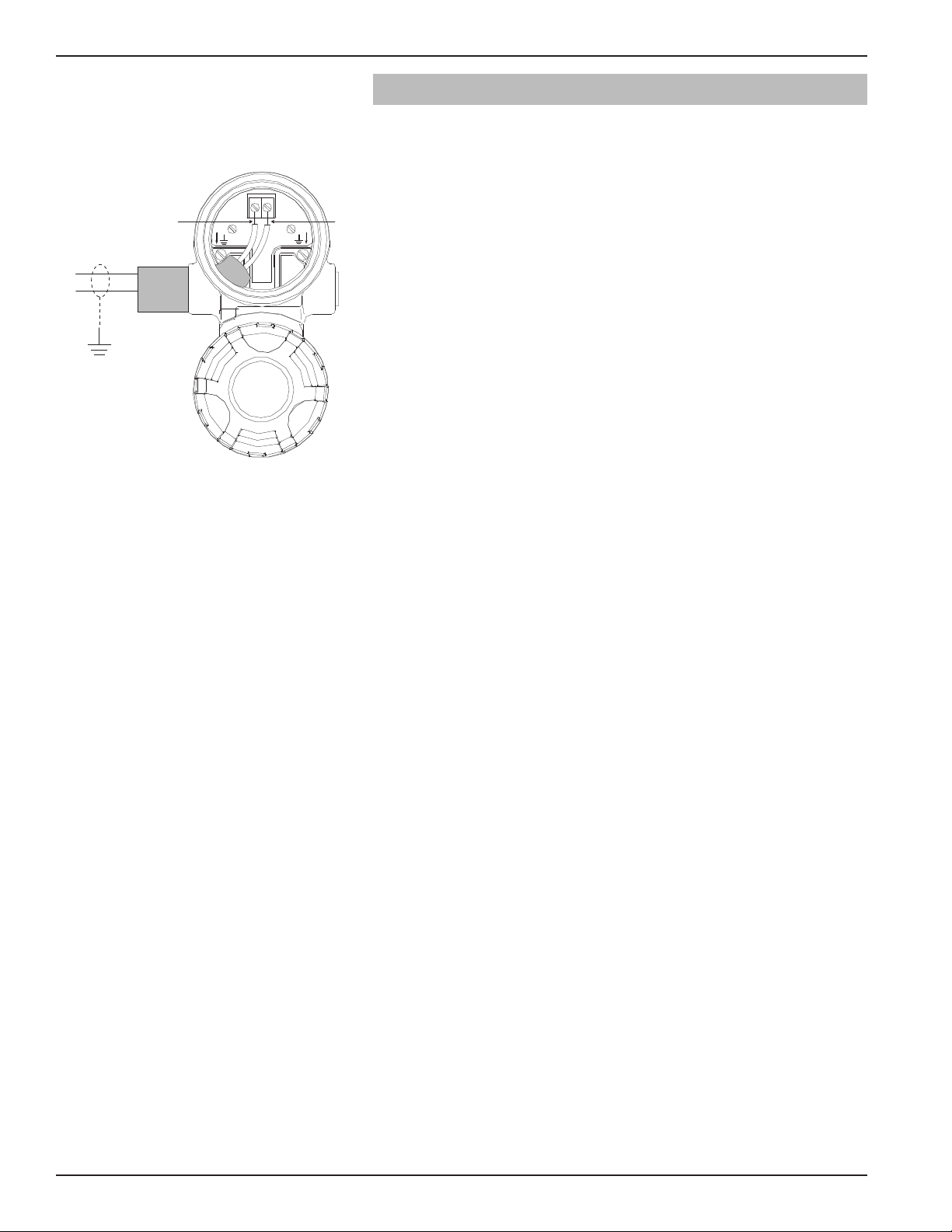
1.5 Wiring
Red (+)
Black (-)
(
+)
(
-)
Caution: The HART version Jupiter transmitter operates at 12–28
DC. The Fieldbus version operates at the 9–32 VDC.
V
Higher voltages will damage the transmitter.
Wiring between the power supply and the Jupiter
transmitter should be made using 18–22 AWG shielded
twisted pair instrument cable. The transmitter enclosure
consists of two compartments. The upper compartment is
used to terminate the field wires (wiring termination compartment), and the lower is the electronics compartment.
The Jupiter is offered for use in Class I, Div 1 areas (flammable gasses may be present). Follow the instructions
below to complete wiring of the instrument.
WARNING! Explosion hazard. Do not disconnect equipment unless
power has been switched off or the area is known to be
non-hazardous.
Figure 4
Wiring Diagram
An explosion proof (XP) installation potentially has flammable vapors or media present. Covers on instruments in
these areas must remain on and tight while power is
applied to the instrument.
Equipment installed in an area classified as Class I, Div 2,
reflects that flammable or explosive vapors may be present.
To install intrinsically safe wiring, make sure the IS barrier
is properly installed in the safe area or suitably installed in
a hazardous area (refer to local plant or facility procedures). Complete the wiring from the barrier to the Jupiter
transmitter. See Agency Specifications– Intrinsically Safe
Installations, Section 2.4.1.
1. Make sure power is off in any junction box which will be
exposed to the atmosphere, unless the area has already
been sniffed and approved free of flammable vapors.
2. The top cover (field wiring compartment) of the Jupiter
transmitter may be removed. Place the cover in a location
where dirt will not get on the threads.
3. Connect shield to an earth ground at the power supply.
4. Connect positive supply wire to the (+) terminal and the
negative supply wire to the (-) terminal.
5. Tighten and check connections, then replace cover.
6. An explosion proof seal is not required unless specifically
noted by the local code.
Note: All local, state and federal regulations and electrical codes
must be adhered to during and after installation.
7. Power may be applied to the instrument when the installation is complete and has been checked by the instrument
engineer or safety officer.
8
46-648 Jupiter Magnetostrictive Transmitters
Page 9

1.6 Configuring the Transmitter
The Jupiter transmitter comes configured from the factory
with regard to probe, float type, and orientation.
Information on configuring the transmitter using a HART
communicator is given in Configuration Using HART,
Section 1.7.
1.6.1 Operating Parameters
Some key information is needed to calibrate the Jupiter
transmitter. Complete the configuration information table.
See Configuration Information, Section 1.3.4.
1.6.2 Transmitter Display and Keypad
The Jupiter transmitter has a liquid-crystal display (LCD)
capable of showing two lines of 8 characters each.
Transmitter measurements and configuration menu screens
are shown on the LCD.
The transmitter default display is the measurement screen.
It cycles every 5 seconds to display STATUS, LEVEL,
%OUTPUT, and LOOP information. The transmitter
defaults to this display after 5 minutes if no keystrokes
are sensed.
The keypad has three arrows used to scroll through the
displays and to calibrate the transmitter – the Up and
Down Arrow ( ) keys and the Enter ( ) key.
Arrows Display Mode Configuration Mode
Up and Down Moves forward and backward Increases or decreases the
Á
Enter Enters the configuration mode Accepts a value and returns
Á
1.6.3 Password Protection (Default = 0)
Function in Function in
Á
in the configuration program value displayed or moves to
from one display to another. another choice.
(noted by an exclamation point to the display mode.
as the last character in the top
display line).
Á
Á
Á
Note: Hold arrow key for
rapid scrolling.
The Jupiter transmitter is password protected to restrict
access to certain portions of the menu structure that affect
the operation of the system. When the proper password is
entered, an exclamation point (!) appears as the last character of the first line of the display. The password can be
changed to any numerical value up to 255. The password
is required whenever configuration values are changed.
46-648 Jupiter Magnetostrictive Transmitters
9
Page 10

The default password installed in the transmitter at the
factory is 0 (password disabled). The last step in the configuration menu provides the option to enter a new password. If 0 is entered as a password, the transmitter is no
longer password protected and any value in the menu can
be altered (except diagnostic values) without entering a
confirming password.
NOTE: If the password is not known, the menu item New Password
displays an encrypted value representing the present password. Call the factory with this encrypted value to determine
the actual password.
1.6.4 Menu: Step-By-Step Procedure
The following table provides a complete explanation of
the software menus displayed by the Jupiter transmitter.
Use this table as a step-by-step guide to configure the
transmitter.
The first column presents the menus shown on the transmitter display. The displays are in the order they would
appear if the arrow keys were used to scroll through the
menu. The numbers are not shown on the display. They
are provided as a reference.
The second column provides the actions to take when
configuring the transmitter. Additional information or an
explanation of an action is given in the third column.
Models with one float:
Level only calibration — proceed to Section 1.6.4.1
Interface only calibration — proceed to Section 1.6.4.2
Models with two floats:
Interface and level calibration — proceed to
Section 1.6.4.3
• The loop output will follow the interface layer.
• Upper liquid level is for display only.
Level and interface calibration — proceed to
Section 1.6.4.4
• The loop output will follow overall liquid level.
• Interface level is for display only.
NOTE: Float 1 is the float nearest to the transmitter head, Float 2 is
the second (i.e., for top-mounted units, Float 1 is the top level
float and Float 2 is the interface layer float; for bottom-mounted models, Float 1 is the interface float, Float 2 is the top level
float).
10
46-648 Jupiter Magnetostrictive Transmitters
Page 11

1.6.4.1 Measurement Type: Level Only
Display Action Comment
Status
1
2
Level
% Output
Loop
Level
xxx.xx
Transmitter Display Transmitter default display. Status, Level, % Output, and Loop
Transmitter Display Level measurement in centimeters or inches
values cycle every 8 seconds.
3
4
5
6
7
8
9
10
11
12
13
14
15
16
% Output
xx.xx%
Loop
xx.xx mA
MeasType
Units
Probe Ln
xxx.xxlu
Set 4mA
xxx.xxlu
Set 20mA
xxx.xxlu
Lvl Ofst
xxx.xxlu
Damping
xx.x s
Fault
22mA
Poll Adr
xx
Trim 4
xxxx
Trim 20
xxxx
Loop Tst
Transmitter Display Level as a percentage of loop current span
ransmitter Display Loop current output (mA)
T
Select type of measurement Choose Lvl Only
Select units of length Choose cm or in
Enter exact length of probe 6–420 inches (15.24–1066.8 cm)
Enter the PV value for 4 mA
Enter 4 mA point in level units
point
Enter the PV value for 20 mA
Enter 20 mA point in level units
point
Enter the level offset value Changes zero level as referenced from probe tip
Enter damping filter time 0–1 second in 0.1 increments
1–25 seconds in 1.0 increments
Select loop current under
3.6 mA, 22 mA or Hold
fault condition
Enter HART polling address
0–15
number
Adjust 4 mA point Attach a meter to the output. If the output does not equal 4 mA,
adjust the value of the display until the meter reads 4 mA
Adjust 20 mA point Attach a meter to the output. If the output does not equal 20 mA,
adjust the value of the display until the meter reads 20 mA
Enter a mA value Set mA output to a value between 3.6 and 22.0 mA
17
DeadBand
xx.x
Factory Setting Diagnostic, factory setting
Enter mounting type MLI Top (external probe; transmitter top mounted)
18
19
20
21
22
23
46-648 Jupiter Magnetostrictive Transmitters
Snsr Mnt
Trim Lvl
xx.xx
F1 Cnts
New Pass
Xxx
Language
(select)
Jupiter HT
Ver 3.0A
Enter value to adjust Level
reading
Display only For factory diagnostic use
Enter new password Use up and down keys to select desired value (0–255)
Select from English or
Spanish
Display only Product firmware version
MLI Bot (external probe; transmitter bottom mounted)
Dir Near (NPT, BSP, and 600# or less flanged probe)
Dir Ext (flanged probes 900# class and over)
-20.00 inches ≤ Trim Lvl ≤ 20.00 inches
Changes display language
11
Page 12

1.6.4.1 Measurement Type: Level Only (cont.)
Display Action Comment
4
2
25
(current status)
26
DispFact
(select)
History
Run Time
Select Yes to display factory
parameter menus
Enter to view history of
exceptions
Display only Elapsed time since power on; reset to zero with History Reset
Diagnostic Display
27
28
29
30
31
32
33
34
35
36
History
Reset
Conv Fct
xxxxxx
Scl Ofst
F1Thresh
F1 Polar
Senstvty
Drv Ampl
ElecTemp
xxx C
Max Temp
xxx c
Min Temp
xxx C
Press Enter and select yes to
lear history
c
Factory parameter Do not adjust
Factory parameter Do not adjust
Factory parameter Do not adjust
Factory parameter Do not adjust
Factory parameter Do not adjust
Factory parameter Do not adjust
Diagnostic Display Present temperature in electronics compartment (degrees C)
Diagnostic Display Maximum electronics temperature recorded (degrees C)
Diagnostic Display Minimum electronics temperature recorded (degrees C)
12
46-648 Jupiter Magnetostrictive Transmitters
Page 13

1.6.4.2 Measurement Type: Interface Only
Display Action Comment
Status
1
2
IfcLvl
% Output
Loop
IfcLevel
xxx.xx
Transmitter Display Transmitter default display. Status, Interface Level, % Output, and
Transmitter Display Interface level measurement in centimeters or inches
Loop values cycle every 8 seconds.
3
4
5
6
7
8
9
10
11
12
13
14
15
16
% Output
xx.xx%
Loop
xx.xx mA
MeasType
Units
Probe Ln
xxx.x
Set 4mA
xxx.xxlu
Set 20mA
xxx.xxlu
Lvl Ofst
xxx.xxlu
Damping
xx.x s
Fault
22mA
Poll Adr
xx
Trim 4
xxxx
Trim 20
xxxx
Loop Tst
Transmitter Display Interface level as a percentage of loop current span
ransmitter Display Loop current output (mA)
T
Select type of measurement Choose Ifc Only
Select units of length Choose cm or in
Enter exact length of probe 6–420 inches (15.24–1066.8 cm)
Enter the PV value for 4 mA
Enter 4 mA point in level units
point
Enter the PV value for 20 mA
Enter 20 mA point in level units
point
Enter the level offset value Changes zero level as referenced from probe tip
Enter damping filter time 0–1 second in 0.1 increments
1–25 seconds in 1.0 increments
Select loop current under
3.6 mA, 22 mA or Hold
fault condition
Enter HART polling address
0–15
number
Adjust 4 mA point Attach a meter to the output. If the output does not equal 4 mA,
adjust the value of the display until the meter reads 4 mA
Adjust 20 mA point Attach a meter to the output. If the output does not equal 20 mA,
adjust the value of the display until the meter reads 20 mA
Enter a mA value Set mA output to a value between 3.6 and 22.0 mA
17
DeadBand
xx.x
Factory Setting Diagnostic, factory setting
Enter mounting type MLI Top (external probe; transmitter top mounted)
18
19
20
21
22
23
46-648 Jupiter Magnetostrictive Transmitters
Snsr Mnt
Trim Ifc
xx.xx
F1 Cnts
New Pass
Xxx
Language
(select)
Jupiter HT
Ver 3.0A
Enter value to adjust Interface
reading
Display only For factory diagnostic use
Enter new password Use up and down keys to select desired value (0–255)
Select from English or
Spanish
Display only Product software version
MLI Bot (external probe; transmitter bottom mounted)
Dir Near (NPT, BSP, and 600# or less flanged probe)
Dir Ext (flanged probes 900# class and over)
-20.00 inches ≤ Lvl Trim ≤ 20.00 inches
Changes display language
13
Page 14

1.6.4.2 Measurement Type: Interface Only (cont.)
Display Action Comment
4
2
25
(current status)
26
DispFact
(select)
History
Run Time
Select Yes to display factory
parameter menus
Enter to view history of
Diagnostic Display
exceptions
Display only Elapsed time since power on; reset to zero with history reset
27
28
29
30
31
32
33
34
35
36
History
Reset
Conv Fct
xxxxxx
Scl Ofst
F1Thresh
F1 Polar
Senstvty
Drv Ampl
ElecTemp
xxx C
Max Temp
xxx c
Min Temp
xxx C
Press Enter and select yes to
lear history
c
Factory parameter Do not adjust
Factory parameter Do not adjust
Factory parameter Do not adjust
Factory parameter Do not adjust
Factory parameter Do not adjust
Factory parameter Do not adjust
Diagnostic Display Present temperature in electronics compartment (degrees C)
Diagnostic Display Maximum electronics temperature recorded (degrees C)
Diagnostic Display Minimum electronics temperature recorded (degrees C)
14
46-648 Jupiter Magnetostrictive Transmitters
Page 15

1.6.4.3 Measurement Type: Interface & Level
Display Action Comment
Status
1
2
IfcLvl
% Output
Loop
IfcLevel
xxx.xx
Transmitter Display Transmitter default display. Status, Interface Level, % Output,
Transmitter Display Interface level measurement in centimeters or inches
and Loop values cycle every 8 seconds.
3
4
5
6
7
8
9
10
11
12
13
14
15
16
17
% Output
xx.xx%
Loop
xx.xx mA
Level
MeasType
Units
Probe Ln
xxx.x
Set 4mA
xxx.xxlu
Set 20mA
xxx.xxlu
Lvl Ofst
xxx.xxlu
Damping
xx.x s
Fault
22mA
Poll Adr
xx
Trim 4
xxxx
Trim 20
xxxx
Loop Tst
Transmitter Display Interface level as a percentage of loop current span
Transmitter Display Loop current output (mA)
Transmitter Display Displays top liquid level
Select type of measurement Choose Ifc&Lvl
Select units of length Choose cm or in
Enter exact length of probe 6–420 inches (15.24–1066.8 cm)
Enter the PV value for 4 mA
Enter 4 mA point in level units
point
Enter the PV value for 20 mA
Enter 20 mA point in level units
point
Enter the level offset value Changes zero level as referenced from probe tip
Enter damping filter time 0–1 second in 0.1 increments
1–25 seconds in 1.0 increments
Select loop current under
3.6 mA, 22 mA or Hold
fault condition
Enter HART polling address
0–15
number
Adjust 4 mA point Attach a meter to the output. If the output does not equal 4 mA,
adjust the value of the display until the meter reads 20 mA
Adjust 20 mA point Attach a meter to the output. If the output does not equal 4 mA,
adjust the value of the display until the meter reads 20 mA
Enter a mA value Set mA output to a value between 3.6 and 22.0 mA
18
DeadBand
xx.x
Factory Setting Diagnostic, factory setting
Enter mounting type MLI Top (external probe; transmitter top mounted)
19
20
21
22
23
46-648 Jupiter Magnetostrictive Transmitters
Snsr Mnt
Trim Lvl
xx.xx
Trim Ifc
xx.xx
F1 Cnts
F2 Cnts
Enter value to adjust Level
reading
Enter value to adjust Interface
reading
Display only For factory diagnostic use
Display only For factory diagnostic use
MLI Bot (external probe; transmitter bottom mounted)
Dir Near (NPT, BSP, and 600# or less flanged probe)
Dir Ext (flanged probes 900# class and over)
-20.00 inches ≤ Trim Lvl ≤ 20.00 inches
-20.00 inches ≤ Trim Ifc ≤ 20.00 inches
15
Page 16

1.6.4.3 Measurement Type: Interface & Level (cont.)
Display Action Comment
24
New Pass
Xxx
Enter new password Use up and down keys to select desired value (0–255)
25
26
27
28
29
30
31
32
33
34
35
36
Language
(select)
Jupiter HT
Ver 3.0A
DispFact
(select)
History
(current status)
Run Time
History
Reset
Conv Fct
xxxxxx
Scl Ofst
F1Thresh
F1 Polar
F2Thresh
F2 Polar
Select from English or
Changes display language
Spanish
isplay only
D
roduct software version
P
Select Yes to display factory
parameter menus
Enter to view history of
Diagnostic Display
exceptions
Display only Elapsed time since power on; reset to zero with History Reset
Press Enter and select yes to
clear history
Factory parameter Do not adjust
Factory parameter Do not adjust
Factory parameter Do not adjust
Factory parameter Do not adjust
Factory parameter Do not adjust
Factory parameter Do not adjust
37
38
39
40
41
42
Senstvty
Drv Ampl
Min Sep
ElecTemp
xxx C
Max Temp
xxx c
Min Temp
xxx C
Factory parameter Do not adjust
Factory parameter Do not adjust
Factory parameter Do not adjust
Diagnostic Display Present temperature in electronics compartment (degrees C)
Diagnostic Display Maximum electronics temperature recorded (degrees C)
Diagnostic Display Minimum electronics temperature recorded (degrees C)
16
46-648 Jupiter Magnetostrictive Transmitters
Page 17

1.6.4.4 Measurement Type: Level & Interface
Display Action Comment
Status
1
2
Level
% Output
Loop
Level
xxx.xx
Transmitter Display Transmitter default display. Status, Level, % Output, and Loop
Transmitter Display Level measurement in centimeters or inches
values cycle every 8 seconds.
3
4
5
6
7
8
9
10
11
12
13
14
15
16
17
% Output
xx.xx%
Loop
xx.xx mA
IfcLevel
MeasType
Units
Probe Ln
xxx.x
Set 4mA
xxx.xxlu
Set 20mA
xxx.xxlu
Lvl Ofst
xxx.xxlu
Damping
xx.x s
Fault
22mA
Poll Adr
xx
Trim 4
xxxx
Trim 20
xxxx
Loop Tst
Transmitter Display Level as a percentage of loop current span
Transmitter Display Loop current output (mA)
Transmitter Display Displays interface level
Select type of measurement Choose Lvl&Ifc
Select units of length Choose cm or in
Enter exact length of probe 6–420 inches (15.24–1066.8 cm)
Enter the PV value for 4 mA
Enter 4 mA point in level units
point
Enter the PV value for 20 mA
Enter 20 mA point in level units
point
Enter the level offset value Changes zero level as referenced from probe tip
Enter damping filter time 0–1 second in 0.1 increments
1–25 seconds in 1.0 increments
Select loop current under
3.6 mA, 22 mA or Hold
fault condition
Enter HART polling address
0–15
number
Adjust 4 mA point Attach a meter to the output. If the output does not equal 4 mA,
adjust the value of the display until the meter reads 4 mA
Adjust 20 mA point Attach a meter to the output. If the output does not equal 20 mA,
adjust the value of the display until the meter reads 20 mA
Enter a mA value Set mA output to a value between 3.6 and 22.0 mA
18
DeadBand
xx.x
Factory Setting Diagnostic, factory setting
Enter mounting type MLI Top (external probe; transmitter top mounted)
19
20
21
22
23
46-648 Jupiter Magnetostrictive Transmitters
Snsr Mnt
Trim Lvl
xx.xx
Trim Ifc
xx.xx
F1 Cnts
F2 Cnts
Enter value to adjust Level
reading
Enter value to adjust Interface
reading
Display only For factory diagnostic use
Display only For factory diagnostic use
MLI Bot (external probe; transmitter bottom mounted)
Dir Near (NPT, BSP, and 600# or less flanged probe)
Dir Ext (flanged probes 900# class and over)
-20.00 inches ≤ Trim Lvl ≤ 20.00 inches
-20.00 inches ≤ Trim Ifc ≤ 20.00 inches
17
Page 18

1.6.4.4 Measurement Type: Level & Interface (cont.)
Display Action Comment
24
New Pass
Xxx
Enter new password Use up and down keys to select desired value (0–255)
25
26
27
28
29
30
31
32
33
34
35
36
Language
(select)
Jupiter HT
Ver 3.0A
DispFact
(select)
History
(current status)
Run Time
History Reset
Conv Fct
xxxxxx
Scl Ofst
F1Thresh
F1 Polar
F2Thresh
F2 Polar
Select from English or
Changes display language
Spanish
isplay only
D
roduct software version
P
Select Yes to display factory
parameter menus
Enter to view history of
Diagnostic Display
exceptions
Display only Elapsed time since power on; reset to zero with History Reset
Press Enter and select yes to
clear history
Factory parameter Do not adjust
Factory parameter Do not adjust
Factory parameter Do not adjust
Factory parameter Do not adjust
Factory parameter Do not adjust
Factory parameter Do not adjust
37
38
39
40
41
42
Senstvty
Drv Ampl
Min Sep
ElecTemp
xxx C
Max Temp
xxx c
Min Temp
xxx C
Factory parameter Do not adjust
Factory parameter Do not adjust
Factory parameter Do not adjust
Diagnostic Display Present temperature in electronics compartment (degrees C)
Diagnostic Display Maximum electronics temperature recorded (degrees C)
Diagnostic Display Minimum electronics temperature recorded (degrees C)
18
46-648 Jupiter Magnetostrictive Transmitters
Page 19

1.7 Configuration Using HART
+
+
-
-
Junction
R
L
> 250 Ω
Control
Room
Display
Power
Supply
Current
Meter
A HART (Highway Addressable Remote Transducer)
remote unit, such as a HART 375 handheld communicator,
can be used to provide a communication link to the
Jupiter transmitter. When connected to the control loop,
the same system measurement readings shown on the
transmitter are shown on the communicator. In addition,
the communicator can be used to configure the transmitter.
The HART communicator may need to be updated to
include the Jupiter software (Device Descriptors). Contact
your local HART Service Center for additional information.
Device manufacturer listed as Magnetrol International.
1.7.1 Connections
A HART communicator can be operated from a remote
location by connecting to a remote junction or by connecting directly to the terminal block in the electronics
housing of the Jupiter transmitter.
HART uses the Bell 202 frequency shift key technique of
high-frequency digital signals. It operates on the 4–20 mA
loop and requires a minimum of 250 Ω load resistance. A
typical connection between a communicator and the
Jupiter transmitter is illustrated.
1.7.2 HART Display Menu
A typical HART communicator display is an 8-line by
21-character LCD. Usually the bottom line of each menu
is reserved for software-defined function keys (F1–F4). For
detailed operating information, refer to the instruction
Figure 5
manual provided with the HART communicator.
The Jupiter transmitter online menu tree is shown in the
following illustration. Open the menu by pressing the
alphanumeric key 1, Device Setup, to display the secondlevel menu.
1.7.3 HART Revision Table
HART Version HCF Release Date Compatible with Jupiter
Software
Dev V2, DD V1 July 2003 Version 2.0A through 2.0B
Dev V3, DD V2 July 2006 Version 3.0A and later
46-648 Jupiter Magnetostrictive Transmitters
19
Page 20

1
Calibration
2
Basic Setup
3 Advanced Setup
4 Diagnostics
5 Review
1
Device Setup
2 Level
1
Level
2
IfcLvl
5
Device Variables
3
% Range
4
Loop
1 Tag
2 Descriptor
3
Date
4 Message
5
Poll Address
6 Final asmbly num
1 4 mA
2 20 mA
3 Other
4 End
1 Faults
2 Warnings
1 View History
2 Reset History
1 Loop Test
2 Present Status
3 Status History
4 Float1 Counts
5 Float2 Counts
6 Elec Temperature
1 Model
2 Manufacturer
3 Orion S/N
4 Firmware Version
5 Coprocessor Version
6 Tag
7 Descriptor
8 Date
9 Message
10 Poll Address
11 Final asmbly num
12 Device ID
13 Measurement Type
14 Level Units
15 Probe Length
16 4mA Set Point
17 20mA Set Point
18 Level Offset
19 Damping
20 System Fault State
21 Deadband
31 Float1 Threshold
32 Float1 Polarity
22 Sensor Mount
23 Trim Level
33 Float2 Threshold
34 Float2 Polarity
35 Sensitivity
36 Drive Amplitude
37 Min Separation
24 Trim Ifc Level
25 SV is
26 Date/Time/Initials
27 4 mA Trim Value
28 20 mA Trim Value
29 Conversion Factor
30 Scale Offset
38 Universal rev
39 Fld dev rev
40 Software rev
41 Num req preams
1 Trim Loop Current
2 Enter Password
3 Factory Settings
4 Max Temperature
5 Min Temperature
7 New User Password
6
Reset Temperatures
1 M
easurement Type
2 Level Units
4 4 mA Set Point
5 20 mA Set Point
6
Level Offset
7
Damping
8
System Fault State
9 Deadband
1
0 Sensor Mount
1
1 Trim Level
12 Trim Ifc Level
1
3 SV is
1
4 Date/Time/Initials
3 Probe Length
1 Orion S/N
2 Device ID
4 Scale Offset
5 Float1 Threshold
6 Float1 Polarity
7 Float2 Threshold
8 Float2 Polarity
9 Sensitivity
10 Drive Amplitude
11 Min Seperation
12 Factory Param 1
13 Factory Param 2
3 Conversion Factor
1.7.4 HART Menu (Jupiter 2.0)
20
46-648 Jupiter Magnetostrictive Transmitters
Page 21

1.8 FOUNDATION Fieldbus Digital Communications
Control Room
Power Supply
Terminator
6234 feet (1900 meters) maximum
PC
Terminator
Power
Conditioner
1.8.1 Description
FOUNDATION Fieldbus™is a digital communications system
that serially interconnects devices in the field. A Fieldbus
system is similar to a Distributed Control System (DCS)
with two exceptions:
• Although a Fieldbus system can use the same physical
wiring as an existing 4–20 mA device, Fieldbus devices are
not connected point-to-point, but rather are multidropped
on a single pair of wires (referred to as a segment).
• Fieldbus is a system that allows the user to distribute
control across a network. Fieldbus devices are smart and
actually maintain control over the system.
Unlike 4–20 mA analog installations in which the two
wires carry a single variable (the varying 4–20 mA current),
a digital communications scheme such as Fieldbus considers
the two wires as a network. The network can carry many
process variables as well as other information. The Jupiter
transmitter is a F
OUNDATION Fieldbus
™
registered device
that communicates with the H1 Foundation Fieldbus protocol operating at 31.25 kbits/sec. The H1 physical layer is
an approved IEC 61158 standard. The illustration below
shows a typical Fieldbus installation.
An IEC61158 shielded twisted pair wire segment can be as
long as 6234 feet (1900 meters) without a repeater. Up to
4 repeaters per segment can be used to extend the distance.
The maximum number of devices allowed on a Fieldbus
segment is 32 although this depends on the current draw
of the devices on any given segment.
46-648 Jupiter Magnetostrictive Transmitters
Typical Fieldbus Installation
21
Page 22

Details regarding cable specifications, grounding, termination,
and other network information can be found in IEC 61158
or at www.fieldbus.org.
1.8.2 Benefits
The benefits of Fieldbus can be found throughout all phases
of an installation:
1. Design/Installation: Connecting multiple devices to a single
pair of wires means less wire and fewer I/O equipment.
Initial Engineering costs are also reduced because the
Fieldbus Foundation requires interoperability, defined as
“the ability to operate multiple devices in the same system,
regardless of manufacturer, without a loss of functionality.”
All Foundation Fieldbus devices must be tested for
interoperability by the Fieldbus Foundation. Orion Jupiter
device registration information can be found listed under
Magnetrol International at www.fieldbus.org.
2. Operation: With control now taking place within the
devices in the field, better loop performance and control are
the result. A Fieldbus system allows for multiple variables to
be brought back from each device to the control room for
additional trending and reporting.
3. Maintenance: The self-diagnostics residing in the smart
field devices minimizes the need to send maintenance
personnel to the field.
1.8.3 Device Descriptions
The function of a Fieldbus device is determined by the
arrangement of a system of blocks defined by the Fieldbus
Foundation. The types of blocks used in a typical User
Application are described as follows:
Resource Block describes the characteristics of the Fieldbus
device such as the device name, manufacturer, and serial
number.
Transducer Blocks contain information such as calibration
data and sensor type. They are used to connect the sensor to
the input function blocks.
Function Blocks are built into the Fieldbus devices as needed
to provide the desired control system behavior. The input
and output parameters of function blocks can be linked
over the Fieldbus. There can be numerous function blocks
in a single User Application.
22
46-648 Jupiter Magnetostrictive Transmitters
Page 23

An important requirement of Fieldbus devices is the interoperability concept mentioned above. Device Description
(DD) technology is used to achieve this interoperability.
The DD provides extended descriptions for each object and
provides pertinent information needed by the host system.
DDs are similar to the drivers that your personal computer
(PC) uses to operate peripheral devices connected to it. Any
Fieldbus host system can operate with a device if it has the
proper DDs for that device.
The most recent DD and Common File Format (CFF) files
can be found on Magnetrol’s web site at magnetrol.com or
fieldbus.org.
1.8.4 Intrinsically Safe
H1 supports Intrinsic Safety (IS) applications with bus
powered devices. To accomplish this, an IS barrier is placed
between the power supply in the safe area and the device in
the hazardous area.
H1 also supports the Fieldbus Intrinsically Safe Concept
(FISCO) model which allows more field devices in a network.
The FISCO model considers the capacitance and inductance
of the wiring to be distributed along its entire length. The
stored energy during a fault will be less and more devices
are permitted on a pair of wires. Instead of the conservative
entity model, which only allows about 90 mA of current, the
FISCO model allows a maximum of 112 mA for Class II C
installations and 319 mA for Class II B installations.
FISCO certifying agencies have limited the maximum
trunk length to 1000 meters and spur length to 30 meters
because the FISCO model does not rely on standardized
ignition curves.
The Orion Jupiter is available with an entity IS, FISCO IS,
and explosion proof approvals.
46-648 Jupiter Magnetostrictive Transmitters
23
Page 24

2.0 Reference Information
MADEINU
SA
This section presents an overview of the operation of the
Jupiter magnetostrictive transmitter, information on troubleshooting common problems, listing of agency
approvals, lists of replacement and recommended spare
parts, and detailed functional, performance and physical
specifications for the instrument.
2.1 Description
The Jupiter is a two-wire, 24 VDC level transmitter based
on the concept of magnetostrictive level measurement
technology.
The Jupiter electronics are housed in an ergonomic housing of two tandem compartments angled at a 45° angle for
ease of wiring and calibration. The electronics compartment is permanently attached to the probe assembly via an
explosion-proof seal.
2.2 Theory of Operation
Magnetostrictive level sensors are based on "time-of-flight"
technology.
Permanent magnets contained within a float device tracks
the process liquid as it changes level. The Jupiter probe is
fixed within close proximity to this magnetic field. A short
current pulse is then applied to a specially designed wire
alloy contained within the probe. The interaction of the
current pulse and magnetic field cause distortion in a small
section of the wire alloy. This in turn creates a vibratory
disturbance which begins to travel through the wire at a
very constant rate of speed. The disturbance is later detected
via a sensing device at the top of the probe and sent to the
electronics unit where it is filtered and amplified.
Extremely accurate level measurement can thus be
obtained precisely measuring the elapsed time between the
current pulse (start), and the returned pulse (stop). The
Jupiter electronics module processes these signals, and then
performs various mathematical operations in order to provide the user with an analog and/or digital representation
of the liquid level.
24
46-648 Jupiter Magnetostrictive Transmitters
Page 25

2.3 Troubleshooting
The Jupiter transmitter is designed and manufactured for years of trouble free operation over a wide
range of conditions. Common transmitter problems are discussed in terms of their symptoms and
recommended corrective actions.
Caution: Do not rotate the Jupiter electronics enclosure or any threaded fittings.
Rotating the electronics enclosure will void warranty and could cause
damage to sensor cables.
2.3.1 Troubleshooting
Problem Solution
Transmitter does not track level (External Mount) Remove transmitter from piping column and test with
re-alignment magnet. Run magnet from bottom to top of
probe. Check zero and span calibration. If no change in
output, consult the factory.
(Direct Insertion) Float stuck, Probe bent (Chamber)
Float inside the level gauge is moving slow Ensure that the magnetic level indicator is plumb.
or not at all.
The process fluid being measured may be too viscous and
heat tracing may be required to make the material more fluid.
The specific gravity of the process fluid and float weight may
need to be reverified.
The liquid being measured may contain magnetic particles
collecting on the magnetic section of the float causing drag.
If this happens magnetic trap assemblies can be purchased
from the factory.
Visual inspection of the float may be required to see if the float
has collapsed.
LEVEL, % OUTPUT, and LOOP values are Basic configuration data is questionable. Reconfigure probe
all inaccurate. length and offset. Ensure the level is accurate. Reconfigure
loop values.
LEVEL, % OUTPUT, and LOOP values fluctuate. Turbulence, increase damping factor until readings stabilize.
Level reading on display is correct, but loop Set poll address to zero
value is stuck at 4 mA.
46-648 Jupiter Magnetostrictive Transmitters
25
Page 26

.3.2 Status Messages
2
Display Message Action Comment
OK None Normal operating mode
Initial None Shown at power-up during
self check
TrimReqd Factory set Loop values are defaults, Consult Factory
loop output may be in accurate
Cal Reqd Factory set default calibration parameters Consult Factory
are in use, level reading may be inaccurate
Lo Temp Present temperature in electronics Transmitter may need to be moved
compartment is below -40° F (-40° C) to ensure temperature is within
specification
Hi Temp Present temperature in electronics Transmitter may need to be moved
compartment is above +176° F (+80° C) to ensure temperature is within
specification
Float 2 No level signal detected from float 2 Make sure 2 floats are being used,
Fail are not damaged, and within
measuring range
Float 1 No level signal detected from float 1 Make sure float is not damaged
Fail and within measurement range
No Signal No signal detected from any float Make sure float is not damaged
and within measurement range
LoopFail Loop current differs from expected value Consult Factory
Snsr Brd Measurement board not responding Consult Factory
DfltParm Internal non-volatile parameters have been Consult Factory
reset to default values
26
46-648 Jupiter Magnetostrictive Transmitters
Page 27

U
nit Equipped
with Display?
Check Voltage at
Terminal Board
No Voltage?
Check Power
Supply and Wiring
Negative
Voltage?
Reverse Wiring
Consult Factory
Check Loop
Current at terminal
Board
Loop Current
Above 23 mA?
Remove Electronic
Module
Loop Current
Above 1 mA?
Replace Terminal
Board
Replace Electronic
Module
Y
es
Yes
Yes
Yes
Yes
Yes
Yes
No
No
No
No
No
No
Display has
Text?
No
Reseat Boards.
Check Power
Supply and Wiring
Loop
Resistance
Wrong?
Correct Loop
Resistance
Start
Good
Display
No
Active
HART
Yes
Failure to Operate
with Correct Loop
Inputs
No
Faint Display?
Yes
Yes
No
Some problems could be
temporarily solved by power
c
ycling the unit. Please call
factory if this problem persists.
Display
Working?
No
Yes
No
RetestYes
HART
Communications
OK?
Voltage Above
36 Volts?
Voltage
< 12V
2 1
3
.3.3 Troubleshooting Flowchart
2
46-648 Jupiter Magnetostrictive Transmitters
27
Page 28

Check Loop
Current at Terminal
Board
Loop Current
Above 23 mA?
Remove Electronic
Module
Loop Current
Above 1 mA?
Replace Terminal
Board
Replace Electronic
Module
Yes Yes
No
No
F
ailure to Operate
with Correct Loop
Inputs
Display
Working?
Yes
No
Retest Unit
Good
Display
Key Board
Responds?
Replace Electronic
Module
No
Check Loop
Current at Wiring
Board
Loop Current
22 - 4.0 mA?
Adjust 4 and 20 mA
Unit has
HART?
HART
Working?
Yes
Yes No
Yes
No
Address
Correct?
Correct Address
Replace Electronic
Module
No
Yes
Unit with Display
Communicates
No Yes
Reseat Boards
Display
Working?
Retest
No
Yes
1
2
4
Display
W
orking?
Yes
Retest Unit
28
continued on next page ¯
46-648 Jupiter Magnetostrictive Transmitters
Page 29

U
nit with Display
Communicates
E
rror
D
isplayed?
N
o Level Signal
Error Codes
N
o
N
o
Y
es
R
eload all
P
arameters
Yes
Yes Yes
Corrupt Display
Text?
Replace Electronic
Module
No
Y
es
Replace Electronic
Module
Same Error
Message?
Retest No
Yes
Out of Calib
Analog Loop
Correct?
Trim 4-20 mA
No
Yes
No
Call Factory
Display Reading
Correctly?
4
Yes
No
U
nit with Display
C
ommunicates
3
Check probe
length
Float is not
detected
Consult Factory
Check Offset
and
4-20 mA
Set Points
46-648 Jupiter Magnetostrictive Transmitters
29
Page 30

2.4 Agency Drawing/Specifications
2.4.1 Agency Drawing
30
46-648 Jupiter Magnetostrictive Transmitters
Page 31

2.4.1 Agency Drawing
46-648 Jupiter Magnetostrictive Transmitters
31
Page 32

2.4.2 Agency Specifications – Explosion Proof Installation
Factory Sealed:
This product has been approved by Factory Mutual Research
FM) and Canadian Standards Association (CSA) as a Factory
(
Sealed device.
NOTE: Factory Sealed: No Explosion Proof conduit fitting (EY seal) is
required within 18" of the transmitter. However, an Explosion
Proof conduit fitting (EY seal) is required between the hazardous and safe areas.
Caution: Grounding (+) will cause faulty operation, but will not
cause permanent damage.
Caution: Do not rotate the Jupiter electronics enclosure or any
threaded fittings. Rotating the electronics enclosure will
void warranty and could cause damage to sensor cables.
2.4.3 Agency specifications ATEX Intrinsically safe
Entity parameters 4–20 mA:
Ui 28.4 Ii = 94 mA Pi = 0.67@ Ci = 2.2 nF Li = 3µH
Entity parameters Fieldbus Fisco:
Ui = 17.5V Ii=380mA Pi = 5.32W Ci = 0.705 nF Li = 3µH
2.5 Maintenance
2.5.1 Keep Control Clean
Periodic inspections are a necessary means to keep your
level control in good working order. This control is a safety
device to protect the valuable equipment it serves.
If the process liquid is clean (no solids or deposits), the
MLI should require minimum maintenance. If the process
liquid is dirty (solids and deposits), it is recommended the
external cage be isolated from the process and flushed periodically. For complete cleaning, drain the unit, remove the
bottom flange and float, inspect cage and float for buildup and clean if required.
32
46-648 Jupiter Magnetostrictive Transmitters
Page 33

➀
➁
➂
➂
➃
➄
2.6 Replacement Parts
2.6.1 Parts Identification
Item Description Part Number
Electronic module
isplay and HART 031-2839-001
D
Display & FOUNDATION fieldbus
Terminal board
HART 030-9151-001
FOUNDATION fieldbus
O-ring (Viton
Aluminum housing cover without glass 004-9193-002
Aluminum housing cover with glass 036-4410-003
®
) 012-2201-237
™
™
031-2840-001
030-9151-004
46-648 Jupiter Magnetostrictive Transmitters
Replacement Parts Diagram
33
Page 34

2.7 Specifications
2.7.1 Performance
Accuracy ±0.015"
Repeatability ±0.005% of full span or 0.005" (0.127 mm) (whichever is greater)
inearity 0.020% of full span or 0.031" (0.794 mm) (whichever is greater)
L
Maximum level rate of change 6 inches per second (models with HART)
Response time 0.1 second
Warm-up <5 second
Upper dead zone None
Lower dead zone <2" (5 cm), SIL 2: <5" (13 cm)
Ambient temperature range Transmitter: -40° to +175° F (-40° to +80° C)
LCD: -10° to +160° F (-20° to +70° C)
Process temperature External Mount: -40° to +248° F (-40° to +120° C)
-320° to +850° F (-195° to +455° C) (with factory insulated MLI)
Direct Insertion: -40° to +200° F (-40° to +95° C)
-40° to +500° F (-40° to +260° C) (high temperature probe)
Humidity 0 to 99% non-condensing
Electromagnetic compliance EN 61326
Environmental protection compliance EN 60654-1
Drop protection compliance EN 50178
Surge Protection Compliance EN 61326 (1000 V)
Maximum Pressure (Direct Insertion) 1700 psig @ +100° F (117 bar @ +38° C)
(limited to the pressure rating of the selected flange or float)
34
46-648 Jupiter Magnetostrictive Transmitters
Page 35

2.7.2 Functional
Measured variables Continuous liquid level
nput power (at terminals) 12-28 VDC
I
Signal output 4–20 mA
4–20 mA with HART 5.0
NAMUR NE 43 compliant with 3.8 to 21.5 mA useable range
Loop resistance 620 maximum ohms @ 24 VDC—refer to chart below
Power consumption 0.7 watt, refer to chart below
Damping 0 to 25 seconds
Error signal 3.6 or 22 mA, field selectable
User interface 3-button keypad, HART communicator, AMS software, PACTware
UNDATION
or FO
Display 2-line × 8-character LCD in inches or cm, mA, and % of level
Resolution Analog: 0.01 mA
Digital: 0.01 units
Span 6 to 400 inches (999 cm)
SIL 2 Safe Failure Fraction (SFF) 90.7%
(consult factory for SIL safety manual)
Fieldbus
™
See Bulletin 46-649 for
F
OUNDATION Fieldbus output
1200
20.5 mA
24 VDC
Ω
1000
800
620
600
400
200
0
0 10 20 30 40 VDC
11
Power Consumption
2.7.3 Physical
Enclosure type Dual compartment
Enclosure material Sand cast aluminum grade 356 HT or 316 stainless steel
Enclosure finish Baked on polymer powder coat
Enclosure rating NEMA 4X7/9, IP 66
Sensor material 316 stainless steel
Sensor length 6 to 400 inches (15 to 999 centimeters)
46-648 Jupiter Magnetostrictive Transmitters
35
Page 36

MADEINUSA
M
ADEINUSA
M
ADEI
N
USA
M
A
D
EI
N
USA
M
ADEI
N
U
S
A
MADEIN
US
A
1
1
(
279)
8
(203)
11.5
(292)
1
2.5
(
318)
11
(279)
8
(203)
11.5
(292)
12.5
(318)
1
1.5
(
292)
8.00
(203)
Flanged or
NPT Connection
nches (mm)
I
Direct Insertion
Top Mount Top Mount Offset Top Mount Offset
High Temperature Bend
36
Bottom Mount Offset Bottom Mount Offset
High Temperature Bend
Gemini – Bottom Mount Offset
and Secondary Transmitter
46-648 Jupiter Magnetostrictive Transmitters
Page 37

Glossary
Accuracy The maximum positive and negative % devia-
ion from the actual value over the total span.
t
ANSI American National Standards Institute.
CSA Canadian Standards Association Canadian, third
party agency that qualifies the safety of electrical equipment.
Damping The mathematical averaging of a meter and/or
output signal to stabilize the effects of a noisy process due
to surface turbulence.
Default Values The main position of the menu structure
that displays the primary measurement values of LEVEL,
% OUTPUT, and LOOP. The transmitter returns to this
position after 5 minutes of inactivity.
DVM/DMM Digital Volt Meter/Digital Multimeter.
Electromagnetic Energy The radiation that travels
through space as electric and magnetic fields varying with
position and time. Examples in increasing frequency:
radio waves, microwave, infrared light, visible light, ultraviolet light, x-rays, gamma waves, and cosmic waves.
EM See Electromagnetic Energy.
EMI Electromagnetic Interference Electrical noise caused
by electromagnetic fields that may affect electrical circuits,
particularly low-power electronic devices.
EN European Normal Committee guidelines in EC
countries that take precedence over local, country guidelines.
Ergonomic A mechanism that considers human capability in its design or function.
Explosion-Proof Enclosure An enclosure designed to
withstand an explosion of gas or vapor within it and prevent the explosion from spreading outside the enclosure.
Fault A defect or failure in a circuit. The current (mA)
value unit defaults to 3.6, 22, or Hold when a diagnostic
condition occurs.
Feedthrough A small, connecting cavity between the
main housing compartments, carrying the cable that supplies the operating energy to the measurement circuitry
and returns the output value proportional to level. This
cavity is potted to maintain the environmental isolation
between the two compartments.
FM Factory Mutual American, third party agency that
qualifies the safety of electrical equipment.
FSK Frequency Shift Keying.
Ground An electrical connection to the Earth’s poten-
tial that is used as a reference for the system and electrical
safety.
Grounded A state where no electrical potential exists
between the ground (green) connection on the transmitter
and the Earth or system ground.
ART Highway Addressable Remote Transducer.
H
Protocol that uses the Bell 202 frequency shift keying
(FSK) method to superimpose low level frequencies
(1200/2000 Hz) on top of the standard 4–20 mA loop
to provide digital communication.
HART ID See Poll Address.
Hazardous Area An area where flammable gases or
vapors are or may be present in the air in quantities sufficient to produce explosive or ignitable mixtures.
IEC International Electrotechnical Commission
Organization that sets international standards for electrical devices.
Increased Safety Designs and procedures that minimize
sparks, arcs, and excessive temperatures in hazardous
areas. Defined by the IEC as Zone 1 environments (Ex e).
Interface: Electrical A boundary between two related,
electronic circuits.
Interface: Process A boundary between two or more
immiscible liquids.
Intrinsic Safety A design or installation approach that
limits the amount of energy that enters a hazardous area
to eliminate the potential of creating an ignition source.
Level The present reading of the height of material in a
vessel.
Linearity The worst case error calculated as a deviation
from a perfect straight line drawn between two calibration
points.
Loop The present reading of the 4–20 mA current output.
Low Voltage Directive A European Community
requirement for electrical safety and related issues of
devices using 50-1000 VDC or 75-1500 VAC.
Magnetic Level Indicator a magnetically coupled,
liquid level indicator which isolates the process in
a sealed non-magnetic piping column. Contrasting
colored flags provide indication of level.
Magnetostrictive Utilizing the Wiedemann effect to create a mechanical torsion or twist in a ferromagnetic wire
which occurs as a result of the interaction between an
electrical pulse on the wire and a magnetic field from the
float.
Measured Value The typical level measurement values
used to track the level of a process: Level, % Output, and
Loop.
Media The liquid material being measured by the level
transmitter.
Multidrop The ability to install, wire, or communicate
with multiple devices over one cable. Each device is given
a unique address and ID.
46-648 Jupiter Magnetostrictive Transmitters
37
Page 38

Nonhazardous Area An area where no volatile mixtures
of vapors/gas and oxygen will be found at any time. Also
called General Purpose Area.
Non-incendive Equipment and wiring which in its normal operating condition is incapable of igniting a specific
hazardous atmosphere or hazardous dust layer.
Offset The distance from the bottom of the tank to the
bottom of the probe.
Password A numerical value between 0 and 255 that
protects stored configuration data from unauthorized
manipulation.
Percent (%) Output The present reading as a fraction of
the 16mA scale (4–20mA).
Poll Address A number between 1 and 15 which sets an
address or location of a device in a multi-drop loop.
Probe A waveguide that propagates an electromagnetic
pulse from the top of the tank into the process fluid.
Probe Length Exact measurement from the bottom of
the process thread connection to the very bottom of the
probe.
Range A value related to probe length (factory setting).
Repeatability The maximum error between two or more
output readings of the same point.
RFI Radio Frequency Interference Electrical noise that
can have an adverse affect on electrical circuits, particularly low-power devices.
Span The difference between the upper and lower limits
of the range.
Specific Gravity (SG) The ratio of the density of a material to the density of water at the same conditions.
Tst Loop Test Loop Built-in system capability to
test/calibrate a loop (or separate loop device) by driving
the transmitter output to a particular value.
Trim 4/Trim 20 Built-in system capability to fine tune
the 4 mA and 20 mA points so the transmitter output
corresponds exactly to user’s meter, DCS input, etc.
Two Wire An electrical instrument design that uses one
set of wires to provide both the supply power and process
measurement signal. The process measurement is achieved
by varying the current of the loop. Also called Loop
Powered.
Units The engineering units used to measure level in the
system. The choices are in (inches) and cm (centimeters).
38
46-648 Jupiter Magnetostrictive Transmitters
Page 39

®
Jupiter Magnetostrictive
Transmitter
Configuration Data Sheet
Copy blank page and store calibration data for future reference and troubleshooting.
Item Value Value Value
Vessel Name
Vessel #
Media & Dielectric
Tag #
Serial # TROUBLESHOOTING
Measurement Type Correct Value Incorrect Value
Units
Probe Length
4 mA Point
20 mA Point
Level Offset
Damping
Fault Choice
HART Poll Address
Trim 4 mA
Trim 20 mA
Loop Test
Deadband
Sensor Mount
Trim Level
Trim Interface
Conversion Factor
Scale Offset
Float 1 Threshold
Float 1 Polarity
Float 2 Threshold
Float 2 Polarity
Sensitivity
Drive Amplitude
Minimum Separation
# of Counts
Software Version
New Password
Name Date/Time
46-648 Jupiter Magnetostrictive Transmitters
39
Page 40

ASSURED QUALITY & SERVICE COST LESS
5300 B elmont Road • Downers Gro ve, Il linois 60515-4499 • 630-969-4000 • Fax 630-969-9489 • www.magne trol.co m
145 Ja rdin Dr ive, U nits 1 & 2 • Conco rd, Ont ario C anada L4K 1X 7 • 90 5-738- 9600 • Fax 9 05-738 -1306
Heiken sstraa t 6 • B 9240 Zele, Belgium • 052 45.11.11 • Fax 0 52 45. 09.93
Regent Busin ess Ct r., Jubilee Rd. • Burge ss Hil l, Sus sex RH 15 9TL U.K. • 0144 4-8713 13 • F ax 014 44-871 317
6646 C omplex Drive • Baton Rouge, Louisiana 70809 • 22 5-906- 2343 • Fax 225-906-2344 • www.ori oninst rument s.com
Copyright © 2010 Magnetrol International, Incorporated. All rights reserved. Printed in the USA.
Service Policy
Owners of Magnetrol/Orion Instruments controls may
request the return of a or any part of an instrument for
complete rebuilding or replacement. They will be rebuilt
or replaced promptly. Instruments returned under our
service policy must be returned by prepaid transportation.
Magnetrol/Orion will repair or replace the control at no
cost to the purchaser (or owner) other than transportation
if:
1. Returned within the warranty period; and
2. The factory inspection finds the cause of the claim
to be covered under the warranty.
If the trouble is the result of conditions beyond our control; or, is NOT covered by the warranty, there will be
charges for labor and the parts required to rebuild or
replace the equipment.
In some cases it may be expedient to ship replacement
parts; or, in extreme cases a complete new instrument, to
replace the original equipment before it is returned. If
this is desired, notify the factory of both the model and
serial numbers of the instrument to be replaced. In such
cases, credit for the materials returned will be determined
on the basis of the applicability of our warranty.
Return Material Procedure
So that we may efficiently process any materials that are
returned, it is essential that a “Return Material
Authorization” (RMA) number be obtained from the factory, prior to the material's return. This is available
through Magnetrol/Orion’s local representative or by
contacting the factory. Please supply the following information:
1. Company Name
2. Description of Material
3. Serial Number
4. Reason for Return
5. Application
Any unit that was used in a process must be properly
cleaned in accordance with OSHA standards, before it is
returned to the factory.
A Material Safety Data Sheet (MSDS) must accompany
material that was used in any media.
All shipments returned to the factory must be by prepaid
transportation.
All replacements will be shipped F.O.B. factory.
No claims for misapplication, labor, direct or consequential damage will be allowed.
HART® is a registered trademark of the HART Communication Foundation
PACTware™ is trademark of PACTware Consortium
CSA logotype is a registered trademark of Canadian Standards Association
Viton® is a registered trademarks of DuPont Performance Elastomers.
Hastelloy® is a registered trademark of Haynes International, Inc.
Monel® is a registered trademark of Special Metals Corporation (Formerly Inco Alloys International)
Tri-Clamp® is a registered trademark of Ladish Co.
©2006 Fieldbus Foundation
BULLETIN: 46-648.7
EFFECTIVE: August 2010
SUPERSEDES: November 2007
 Loading...