

Page 1

INSTRUCTION MANUAL
Orion StarSeeker™ III
GoTo Telescopes
#10065 StarSeeker III 102mm Refractor, #10066 StarSeeker III 90mm Mak-Cass
#10067 StarSeeker III 102mm Mak-Cass, #10069 StarSeeker III 127mm Mak-Cass
#10068 StarSeeker III 114mm Reflector, #10070 StarSeeker III 130mm Reflector
Providing Exceptional Consumer Optical Products Since 1975
#10066
Customer Support:
www.OrionTelescopes.com/contactus
Corporate Offices:
89 Hangar Way, Watsonville CA 95076 – USA
IN 520 Rev. A 02/14
Page 2

Optical tube
EZ Finder II
Battery case
Accessory tray
Mount arm
Tube lock bolt
Coupling knob
Tripod
leg brace
Eyepiece,
25mm
Star diagonal
1.25"
Accessory
adapter
(visual back)
Eyepiece,
10mm
Tripod leg
Figure 1. The StarSeeker III 90mm GoTo Telescope
2
Hand
controller
Leg clamp knob
Page 3

Table of Contents
Introduction
Introduction ............................ 3
Parts List .............................. 3
Assembly .............................. 4
Learning to Use the EZ Finder, Eyepieces,
and Focuser ............................ 6
The EZ Finder II ................................6
Eyepieces and Magnification ......................7
Focusing ......................................7
Powering the StarSeeker III .......................7
The SynScan GoTo Hand Controller –
Overview ..............................8
Initial Setup ............................8
GoTo Star Alignment ..................... 9
Brightest Star Alignment. . . . . . . . . . . . . . . . . . . . . . . . . 10
2-Star Alignment ...............................11
Locating Objects ....................... 11
SynScan’s Object Database ......................11
Selecting an Object ............................ 11
Take a Guided Tour! ............................11
Select Using the Object Type Shortcut Keys .........11
Select Using the Object or Menu Shortcut Keys ...... 12
Identifying an Unknown Object ....................12
Other Features & Functions .............. 12
Utility Functions ...............................12
Setup Functions ...............................12
Pointing Accuracy Enhancement (PAE) .............13
Saving and Accessing User-Defined Objects .........13
Controlling Your StarSeeker III via Computer and
Astronomy Software ............................14
Updating Firmware ............................. 14
Collimation of StarSeeker III Reflectors .............14
Appendix A – SynScan Menu Tree ........15
Appendix B – Time Zone Map ............16
Appendix C – Sky Maps (for selection of
alignment stars) ........................ 17
Specifications .........................21
WARNING: Never look directly at the Sun with the
naked eye or with a telescope – unless you have
a proper solar filter installed over the front of the
telescope! Otherwise, permanent, irreversible eye
damage may result.
Congratulations on your purchase of an Orion
StarSeeker III GoTo telescope! Simple and friendly to use, the StarSeeker combines state-of-theart GoTo pointing technology with sharp optics
in a portable package that makes observing the
night sky both remarkably easy and wonderfully
rewarding.
This manual covers a variety of different
StarSeeker models. Some sections may be specific to a particular type of telescope, but most apply
generally to features and procedures common to
all of the telescopes.
Take time to read through this manual before embarking
on your journey through the heavens. It may take a couple of observing sessions to become familiar with all of the
StarSeeker’s features. The StarSeeker’s hand controller displays step-by-step instructions to guide you through the alignment procedures needed to get the telescope up and running
in minutes. Use this manual in conjunction with the on-screen
instructions provided by the hand controller. The manual gives
detailed information regarding each step as well as needed
reference material and helpful hints guaranteed to make your
observing experience as easy and pleasurable as possible.
Parts List
Qty. Description
1 Optical Tube Assembly
1 Mount Arm
1 Tripod
1 Accessory Tray with Hand Controller Holder
1 GoTo Hand Controller
1 Hand Controller Cable
1 EZ Finder II Reflex Sight (with bracket)
1 25mm Explorer II Eyepiece
1 10mm Explorer II Eyepiece
1 Star Diagonal, 1.25" (Mak-Cass and Refractor
models only)
1 Quick-collimation Cap (Reflector models only)
1 Battery Pack (batteries not included)
1 Objective Cover
1 2mm Allen Wrench (Reflector models only)
1 Serial RS-232 cable
1 Starry Night Software Digital Download Insert
Open the shipping box and, referring to the above Parts List
and Figure 2, check that all the parts are present. Remove
all of the accessories from their individual boxes and bags.
3
Page 4

Battery case
PC interface
(serial) cable
Hand
controller
cable
Hand
controller
Collimation cap
(with reflector
models only)
Star diagonal
(with refractor
and Mak-Cass
models only)
Compass
Accessory
tray
Eyepieces
Optical tube
(90mm MakCass shown)
Dust cover
Tripod
Mount
arm
EZ Finder II
Figure 2. Components of the StarSeeker III GoTo telescope. (StarSeeker III 90mm Mak-Cass shown)
Remember to save all of the original packaging in case the
scope needs to be returned to Orion for warranty repair, or
should you wish to return the scope under the 30-day return
policy. Especially in the latter case, the original packaging is
required. If anything is missing, contact Orion Customer Service at (800) 676-1343, or support@telescope.com.
Assembly
Setting Up the Tripod
1. Remove the tripod from the box and spread the legs
apart until the center leg brace is fully extended.
2. Locate the accessory tray and center it on top of the
tripod center support brace (see Figure 3). Turn the tray
attachment knob until the tray is securely attached. The
Figure 3. The round accessory tray attaches to the tripod
leg brace with the captive screw on the brace.
4
Page 5

Mount arm
base
Tripod
mounting
platform
Coupling
knob
Figure 4. The mount arm attaches to the tripod mounting
platform with the large coupling knob.
Tube lock
bolt
Dovetail
saddle
bracket on the side of the tray is a holder for the GoTo
hand controller.
It is a good idea to adjust the height of the tripod before
attaching the fork arm and optical tube. Minor adjustments
can be made later. To adjust the height of the tripod legs:
3. Loosen the tripod leg clamp knob located on the side of
each leg (Figure 1).
4. Extend the inner portion of each leg to the desired
length.
5. Tighten the tripod leg clamp knobs to secure each leg in
place.
Also, be sure to tighten the large wingnuts at the top of each
leg, where it attaches to the tripod mounting platform.
Attaching the Mount Arm to the Tripod
1. Place the mount arm base inside the tripod mounting
platform. See Figure 4.
2. Thread the coupling screw into the hole at the bottom of
the mount arm base and tighten with the large coupling
knob.
Attaching the Telescope Tube to the Mount Arm
1. Unthread the tube lock bolt until the bolt tip is not
protruding into the saddle slot.
2. Slide the tube dovetail bar into the saddle on the mount
arm as shown in Figure 5, and secure it by tightening the
tube lock bolt.
Dovetail
bar on
optical tube
Figure 5. Insert the dovetail bar on the optical tube into the
saddle on the mount arm.
EZ Finder II
Thumbscrew
Eyepiece
Star
diagonal
2"
Accessory
collar
1.25"
Adapter
Focus
wheel
(x2)
Focuser
drawtube
Figure 6. The focuser and installed accessories.
(StarSeeker III 102mm Refractor shown)
WARNING: NEVER ATTEMPT TO MOVE THE TELESCOPE BY HAND! Otherwise, the gears and motors may
be damaged. Move the telescope only electronically with
the hand controller.
Inserting the Star Diagonal (Mak-Cass and Refractor)
and/or Eyepiece
A star diagonal is used with the Maksutov-Cassegrain and
refractor models to divert the light at a right angle from the light
path of the telescope. This allows you to observe in positions
that are more comfortable than if you were to look straight
through. A diagonal is not used with Newtonian reflectors;
none is included with the StarSeeker reflector models.
To attach the star diagonal:
1. Remove the protective dust cap from the 1.25" accessory
adapter.
2. Loosen the two thumbscrews on the 1.25" adapter and
slide the chrome portion of the star diagonal into the
adapter (see Figure 6).
5
Page 6

3. Tighten the thumbscrews to hold the star diagonal in
place.
The eyepiece, or ocular, is the optical element that magnifies
the image focused by the telescope.
The eyepiece fits directly into the 1.25" accessory adapter or
star diagonal. To install one of the included eyepieces:
1. Loosen the thumbscrew on the 1.25" adapter or star
diagonal.
2. Slide the chrome barrel of the eyepiece into the adapter
or diagonal (Figure 7).
3. Tighten the thumbscrew to hold the eyepiece in place.
Installing the EZ Finder II
Before installing the EZ Finder II (Figure 8) on the telescope,
you may need to insert the included CR2032 3V lithium button cell battery. In some cases, the battery may have been
installed at the factory. If there is a small plastic tab sticking
out from the battery compartment cover, you must remove it
for the battery to make contact with the EZ Finder’s electronic circuitry. The tab can then be discarded. If the battery was
not installed at the factory and is provided separately, you will
have to install it, as follows:
1. Insert a small, flat-blade screwdriver into the notch in
the battery compartment cover and gently pry it off
(Figure 8).
2. Slide the battery under the retaining clip with the positive
(+) side facing down (touching the clip).
3. Then press the battery compartment cover back on.
Should the battery die, replacement CR2032 batteries are
available at many stores where small batteries are sold or
online.
To attach the dovetail mounting bracket to the EZ Finder II,
loosen the two thumbscrews on the bottom rail of the EZ
Finder II. Slide the EZ Finder II onto the bracket and tighten
the two thumbscrews (See Figure 8). Then simply slide the
mounting bracket’s foot into the dovetail mounting shoe as
shown in Figure 9 and tighten the thumbscrew on the shoe to
secure the mounting bracket.
The EZ Finder II should be oriented so that the sight tube is
facing the front of the telescope, as shown. Tighten the thumbscrew on the dovetail shoe to secure the EZ Finder II in place.
Learning to Use the
EZ Finder, Eyepieces,
and Focuser
The EZ Finder II
The EZ Finder II works by projecting a tiny red dot (it is not
a laser beam) onto a lens mounted in the front of the unit.
When you look through the EZ Finder II, the red dot will appear
to float in space, helping you to pinpoint your target object
Figure 7. Insert the chrome barrel of the eyepiece into
the diagonal and secure with the two thumbscrews. For the
StarSeeker III reflector models, the eyepiece is inserted
directly into the focuser’s accessory adapter.
Sight tube
ON/OFF
Brightness control
Azimuth
Altitude
adjustment
control
Dovetail
tightening
screws
Figure 8. The EZ Finder II’s On/Off and adjustment knobs.
(Figure 10). The red dot is produced by a light-emitting diode
(LED) near the rear of the sight. The 3V lithium battery provides the power for the diode.
For the EZ Finder II to work properly, it has to be aligned with
the telescope. When the two are aligned, a celestial object that
is centered on the EZ Finder II’s red dot should also appear
in the center of the telescope’s eyepiece. Alignment of the
EZ Finder II is easiest during daylight, before observing at
night. Aim the telescope at a distant object such as a telephone pole or roof chimney and center it in the telescope’s
eyepiece. The object should be at least 1/4 mile away. Now
turn on the EZ Finder II and look though it. Without moving the
main telescope, use the EZ Finder II’s azimuth (left/right) and
altitude (up/down) adjustment knobs (see Figure 8) to position
the red dot on the object in the eyepiece. When the red dot is
centered on the distant object, check to make sure that the
object is still centered in the telescope eyepiece. If it isn’t, re-
adjustment
control
Battery
compartment
cover
6
Page 7

Thumbscrew
Dovetail
shoe
Figure 9. Insert the EZ Finder II into its dovetail shoe in the
orientation shown and secure it with the thumbscrew.
Figure 10. The EZ Finder II superimposes a tiny red dot on
the sky, showing right where the telescope is aimed.
center it and adjust the EZ Finder II’s alignment again. When
the object is centered in the eyepiece and on the EZ Finder’s
red dot, the EZ Finder II is properly aligned with the telescope.
Once aligned, EZ Finder II will usually hold its alignment even
after being removed and remounted. Otherwise, only minimal
realignment will be needed.
Turn the ON/OFF knob (see Figure 8) clockwise until you
hear the “click” indicating that power has been turned on. Look
through the back of the reflex sight with both eyes open to
see the red dot. Position your eye at a comfortable distance
from the back of the sight. In daylight you may need to cover
the front of the sight with your hand to be able to see the dot,
which is purposefully quite dim. The intensity of the dot is
adjusted by turning the ON/OFF knob. For best results when
stargazing, use the dimmest possible setting that allows you
to see the dot without difficulty. Typically a dimmer setting is
used under dark skies and a brighter setting is needed under
light-polluted skies or in daylight.
At the end of your observing session, be sure to turn off the
ON/OFF knob on the EZ Finder II.
Eyepieces and Magnification
Eyepieces are commonly referred to by their focal length and
barrel diameter. The focal length of each eyepiece is typically printed on the eyepiece body. For example, StarSeeker
telescopes include two 1.25" diameter eyepieces; one with
25mm and the other with 10mm focal length. The longer the
focal length (i.e., the larger the number), the lower the eyepiece power or magnification; and the shorter the focal length
(i.e., the smaller the number), the higher the magnification.
Generally, low or moderate power will produce the sharpest
images when viewing.
You can change the magnifying power of your telescope just
by changing the eyepiece (ocular). To determine the magnification of your telescope, simply divide the focal length of the
telescope by the focal length of the eyepiece used.
Telescope Focal Length (mm)
Eyepiece Focal Length (mm)
= Magnification
For example, the StarSeeker III 114mm reflector has a focal
length of 500mm, which when used with the supplied 25mm
eyepiece yields 20x magnification:
500mm
25mm
= 20x
The magnification provided by the 10mm eyepiece is:
500mm
10mm
= 50x
Although the power can be varied, each instrument under
average skies has a limit to the highest useful magnification.
The general rule is 2x per millimeter of aperture is as high as
you can reasonably go (with optional eyepiece and possibly a
Barlow lens). For example, the StarSeeker III 114mm reflector has a primary mirror that’s 114mm in diameter. So 114mm
times 2x per millimeter = 114 x 2 = 228. Thus, 228x is the
highest useful magnification one can normally achieve under
ideal seeing conditions with this telescope. (Trying to go higher
would likely just result in dim, blurry images.) Although this is
the maximum useful magnification, most observing will yield
best results at lower powers.
Focusing
To focus, if you have a StarSeeker III Newtonian reflector or
refractor telescope, simply turn either of the two focus wheels
on the focuser (see Figure 6, for example) until the image looks
sharp. For the Maksutov-Cassegrain models, the focus knob
resides to the right of the visual back, or accessory adapter.
Make sure you’re aimed at something far off in the distance. If
you don’t see an image at first, keep turning the focus knob in
one direction while looking through the eyepiece; if you reach
the end of the focuser travel start turning the focus knob in the
other direction. Eventually, you should see the object you’re
aimed at come into view. After going just past the focus point in
one direction, and then in the other direction, you will then be
able to home in on the exact focus point, at which the image
looks sharpest.
Powering the StarSeeker III
Your StarSeeker III mount can be powered by the supplied battery pack, or by an optional AC-to-DC adapter or Dynamo Pro
12V DC field battery. The battery pack requires 8 user-sup-
7
Page 8

plied AA alkaline batteries. To power the StarSeeker III mount,
insert the plug of your desired power supply into the 12V jack
located on the mount arm (Figure 11). Once the power supply is plugged in, the LCD on the StarSeeker’s hand controller will light up and display the opening message. To turn the
StarSeeker III mount off, simply disconnect the power supply
cable from the jack on the mount. (There is no On/Off switch.)
Hand
controller
jack
The SynScan GoTo Hand
Controller – Overview
The “command center” of the StarSeeker telescope is the
SynScan GoTo hand controller. In conjunction with the precision servo motors built into the mount, the user-friendly
SynScan controller allows automated, pinpoint slewing of the
telescope to any celestial object in its 42,900-object database,
saving you the trouble of manually searching for them. You can
even tour a pre-selected list of the finest showpiece objects
visible in tonight’s sky with just a few button pushes. Once your
target object has been acquired, the mount tracks its motion
across the sky to keep it in the field of view.
Keypad Layout and Connection Ports
The hand controller’s two-line liquid crystal display (LCD) is
backlit for comfortable viewing. The contrast of the text and the
brightness of the red backlight are both adjustable.
There are four categories of control keys on the hand controller (Figure 12A):
1) Mode keys
2) Directional keys
3) Scroll keys
4) Dual Purpose keys
Mode Keys
The three mode keys are ESC, ENTER, and SETUP.
• ESC is used to escape from a certain command or go back
a level in the menu tree.
• SETUP is a quick hot key that takes you to the Setup
submenu.
• ENTER is used to select the functions and submenus in the
menu tree, and to confirm certain functional operations.
Direction Keys
The direction keys (Up, Down, Left, Right) allow the user to
have complete control of the mount at almost any step in
operation. These controls are locked out when the telescope is
slewing to an object. The direction keys are very helpful when
initially aligning the mount, centering objects in the eyepiece
field of view, slewing, and manually guiding. The left and right
direction keys can also be used to move the text cursor when
entering data on the hand controller.
Scroll Keys
The Up and Down scroll keys allow you to scroll up and down
within the menu tree or selections displayed on the hand controller screen.
Power jack
Figure 11. Jacks for the power cable and hand controller
cable are located at the bottom of the mount arm.
Dual Purpose (Shortcut) Keys
The Dual Purpose keys serve two distinct purposes. They are
used for data entry and as quick-reference (shortcut) keys.
• TOUR: Takes you on a preset tour of the best night sky
objects visible
• RATE: Changes the speed of the motors when the
directional buttons are pressed. There are 10 slew speeds
to choose from, with 0 being the slowest and 9 being
the fastest.
• UTILITY: Displays functions such as “Show Position”,
“Display Time”… etc.
• USER: Gives access to up to 25 user-defined coordinates
• INFO: Identifies the object(s) the mount is currently
pointing to
• NGC, IC, M, PLANET, and OBJECT: Allows direct access
to database of thousands of objects
Connecting the SynScan Hand Controller
1. Plug the larger of the two connectors on the coil cable
into the RJ-45 jack on the bottom of the SynScan hand
controller (Figure 12B).
2. Then plug the smaller connector into the RJ-12 port at
the base of the mount arm (Figure 11).
NOTE: The other, RJ-12 jack on the bottom of the hand
controller is a serial port used for controlling the telescope via a computer running a compatible astronomy
software program, or for updating the SynScan’s firmware, both of which are covered later.
Initial Setup
1. Make sure the mount is level to the ground.
2. After installing eight AA batteries into the battery case,
plug the power cable from the battery pack into the
power jack on the mount arm (Figure 11). The hand
controller will issue a long beep and display the firmware
version. Press ENTER.
8
Page 9
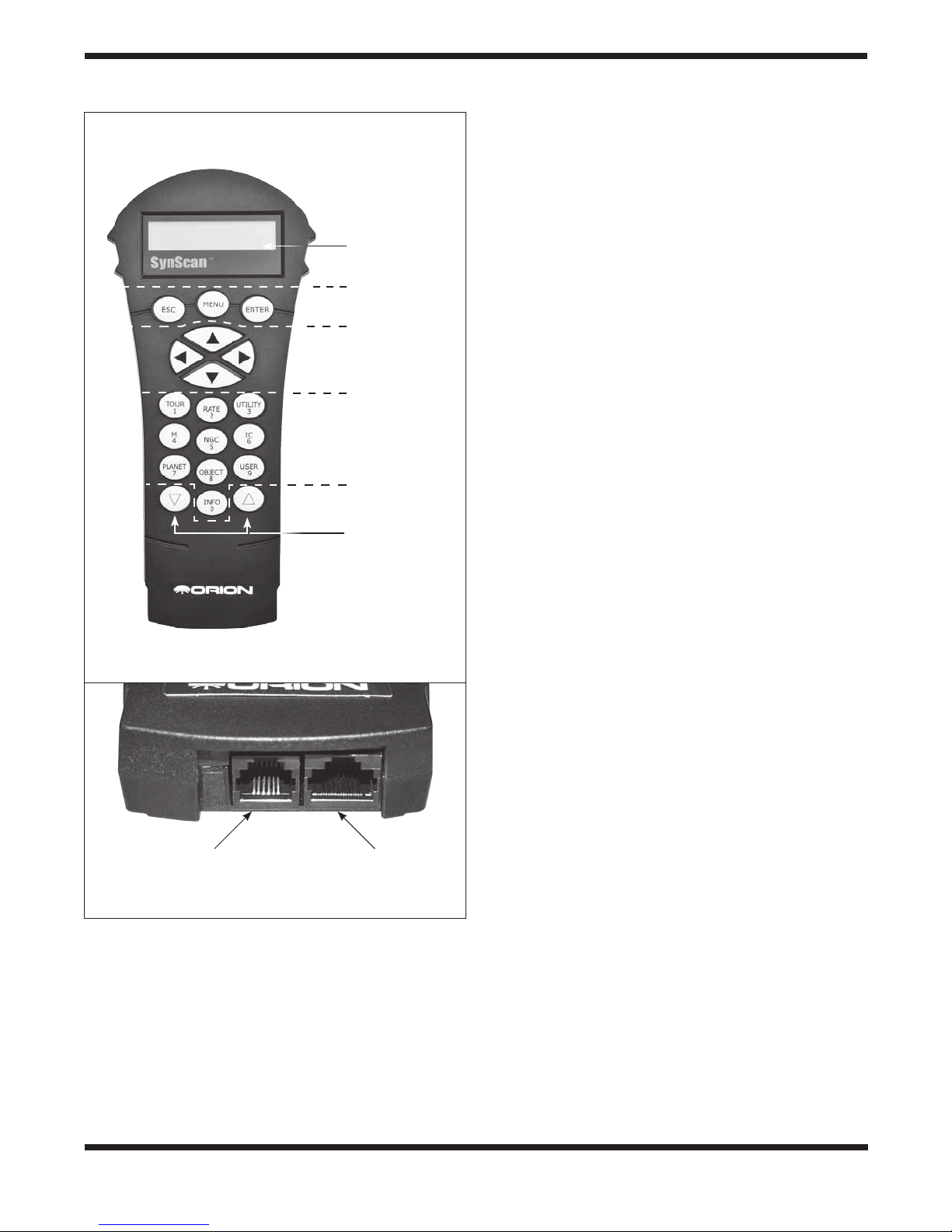
A.
B.
Serial
cable port
(RJ-12)
Display
screen
Mode keys
Direction
keys
Dual purpose
(shortcut)
keys
Scroll keys
Hand controller
cable port
(RJ-45)
Enter the latitude and longitude of your current location using
the numeric keypad and scroll buttons. If you do not know the
latitude and longitude coordinates of your viewing location,
consult an atlas or look them up on the internet (i.e., search
“[your location] coordinates”).
• Use the scroll keys to choose between E or W (for
longitude) and N or S (for latitude).
• Press ENTER to confirm the entered coordinates and
proceed to the next step.
NOTE: Latitude and longitude coordinates must be
entered in degrees and arcminutes. If your atlas or other
reference source provides coordinates in decimal values (i.e., latitude = 36.95 N), you must convert that into
degrees and arcminutes (i.e., latitude 36.95 N = latitude
36°57’ N). There are 60 arcminutes in 1 degree.
5. Enter the current time zone in which you are observing
in hours (see Appendix B), using the scroll keys and
numeric keypad (+ for East, – for West) The “+” sign is
used for time zones in the Eastern Hemisphere (Europe,
Africa, Asia, Oceania), while the “-” sign is used for time
zones in the Western Hemisphere (North and South
America). So for Pacific Standard Time (PST) you would
enter -08:00. Press ENTER to confirm.
6. Enter the date in the format mm/dd/yyyy using the
numeric keypad. Press ENTER to confirm your choice.
7. Enter your current local time using the 24 hour time
mode (e.g., 2:00 p.m. = 14:00). Press ENTER to view the
time you entered. If the time is incorrect, press ESC to go
back to the previous screen. If the time is correct, press
ENTER to confirm.
8. When “Daylight Saving?” is displayed, use the scroll keys
to select “Yes” or “No”. “YES” indicates the time entered
in the previous step is Daylight Saving time, while “NO”
indicates the time entered is Standard time. Press the
ENTER key to confirm and proceed to the next step.
9. Now the screen will display “Begin Alignment?” and ask
you to select 1) YES or 2) NO. Press “1” or ENTER to
start the alignment process. Press “2” or ESC to skip the
alignment process.
NOTE: The hand controller LCD’s red illumination will dim
and the keypad backlighting will turn off if idle for 30 seconds. Pressing any key turns the lighting back on.
Figure 12. A) The SynScan GoTo hand controller,
B) Hand controller cable and serial cable ports on the
bottom end of the controller
3. The hand controller will scroll a warning message about
the danger of viewing the Sun with a telescope without
a properly fitted solar filter. Press ENTER to confirm you
have read the warning message and proceed to the next
step. Press ESC to return to the previous step.
4. The LCD screen will display “Enter Location” on the first
line, and longitude and latitude values on the second line.
GoTo Star Alignment
In order for your StarSeeker III GoTo telescope to accurately
locate and point to objects in the sky, it must first be aligned
on known positions (stars) in the sky. With that information, the
mount can create a model of the sky and of the movements of
astronomical objects.
There are two methods for aligning your StarSeeker III telescope, and they are very similar: Brightest Star Alignment and
2-Star Alignment. Both involve identifying and pointing the
telescope to two different bright stars in the night sky. Both
9
Page 10

alignment methods provide the same level of precision. The
only difference is that for the Brightest Star alignment, the
hand controller will prompt you to select the first alignment star
from a directional region of the sky and will provide a short list
of the brightest stars in that region. With the 2-Star alignment
procedure the list of eligible stars is not grouped by region of
sky.
For the novice stargazer unfamiliar with the night sky or the
names of brighter stars, some might find the Brightest Star
Alignment to be the easier of the two methods. The 2-Star
method is for users who know the names of at least some
stars in the night sky. To assist you in performing the alignment by either method, we have included in Appendix C a set
of star charts with the names of some bright alignment stars
indicated for easy reference.
Note: Before performing any of the alignment methods,
be sure that your finder scope is precisely aligned with
the telescope tube.
To get the most accurate star alignment:
• The two alignment stars you choose should be at least 60
degrees apart. (For reference, your fist held at arm’s length
spans about 10 degrees.)
• The two stars should be roughly at the same altitude.
• Use a high-power eyepiece, such as the 10mm focal length
eyepiece included with the StarSeeker III.
• When centering an alignment star in the eyepiece, always
end the procedure by using the UP and RIGHT direction
keys.
• If there is overshoot when centering an alignment star in
the eyepiece with the UP and RIGHT keys, use the LEFT
or DOWN keys to pull the star back to the edge of the field
of view and then use the RIGHT and UP keys to center the
star again.
Brightest Star Alignment
Aligning the 1st Star
1. Select “Brightest Star” as your Alignment Method. Press
ENTER.
2. The hand controller will prompt you to “Select Region.”
Referring to Figure 13, choose the region that
corresponds with where you see the brightest star in the
sky. There are eight overlapping regions to choose from,
each covers a 90-degree span in azimuth. The direction
you choose will only affect your alignment star selection;
you will still be able to choose objects to view across the
entire sky once the alignment is complete. Referring to
the included compass may be helpful during this process.
The red portion of the pointer points North, so orient the
compass so that the “N” (0 degrees) is directly under the
red tip.
3. After you have selected a region of the sky, the hand
controller will generate a list of the brightest stars in that
region. Only stars or planets brighter than magnitude
1.5 will appear in the list, and only if they are between
10 and 75 degrees in elevation. If none is found meeting
N (0˚)
R
E
N
H
S
T
R
O
K
S
T
S
E
E
W
H
T
Y
K
S
Y
U
O
S
N
R
S (180˚)
K
Y
N
O
R
T
H
E
A
S
A
S
T
S
K
Y
S
O
U
T
H
E
(45˚)
E
A
T
S
S
K
T
Y
E
R
S
O
U
T
H
E
Y
N
S
K
(135˚)
E (90˚)
W (270˚)
(315˚)
(225˚)
N
Y
W
H
K
T
S
R
O
N
N
R
E
Y
T
K
S
S
E
T
S
W
Figure 13. Directional regions of the sky used in the
“Brightest Star” alignment method.
Star Name
Brightness Order
Orientation
Azimuth Angle
1. Capella
NE 35.3
0.1
15.7
Magnitude
Altitude Angle
Figure 14. Alignment star information displayed on LCD.
those criteria, the hand controller will display “No object
found in this region.” Press ENTER or ESC and select
another region of sky.
4. Now, use the Scroll keys to scroll through the list of bright
stars. There will only be a few stars, at most, on the list,
and sometimes only one star. The hand controller will
display the name and magnitude of the bright star on the
first line, and its position on the second line (Figure 14).
On the second line, the first number is the star’s azimuth
angle, or E-W coordinate, in degrees, and the second
number is its altitude above the horizon in degrees.
These coordinates provide a simple way to identify the
bright star you have chosen. When you are confident the
hand controller is displaying the name of the bright star
you wish to align on, press ENTER.
5. The mount will NOT slew to the first selected bright star
automatically. Instead, you will use the direction keys to
slew the telescope to the 1st alignment star selected in
the previous step. Center the 1st align ment star in the
field of view of the EZ Finder II first, then center it in the
telescope eyepiece. Press ENTER to proceed to the next
step.
NOTE: You can change the slew speed by pressing the
RATE key, and then select a number between 0 (slowest)
and 9 (fastest). Generally, a slewing rate of 5 or 6 is best
for centering the star in the EZ Finder II, and a rate of 2
10
Page 11

or 3 works best for centering the star in the telescope’s
eyepiece.
NOTE: The SynScan will beep once when the mount has
finished slewing to a target object. Do not try to move the
telescope using the directional keys before you hear the
beep. SynScan will only respond to the ESC key while
slewing.
Aligning the 2nd Star
1. Once the first alignment star has been centered in the
eyepiece, the SynScan will prompt you to “Choose 2
Star.” If the fist alignment “star” was actually a planet,
you’ll be prompted to re-select a first alignment star.
2. Scroll through the list using the Scroll keys and refer to
the appropriate star chart in the back of this manual to
choose a second alignment star, then press ENTER.
The mount will now automatically slew to the selected
star, which should land in or near the field of view of the
EZ Finder. After the mount stops, the hand controller
will give a long beep and display “Use dir. keys to center
object.” After you’ve centered it in the finder scope
and then in the telescope’s eyepiece, press ENTER. If
both alignment stars were properly aligned, the LCD
will display “Align ment Successful.” Press ENTER
to complete the alignment process. If the message
“Alignment Failed” displays, it usually means the star
positions do not correspond with the location and date/
time information input during setup. Please check your
user initialization settings before starting again.
Cancellation During Alignment Process
1. While the mount is slewing during the alignment, you
may press the ESC key to stop the mount. The hand
controller screen will display “Mount stopped. Press any
key…”
2. Press any key and the SynScan hand controller will ask
you to select another align ment star.
3. Press the ESC key again, and the LCD screen will
display “Exit Alignment? 1) YES 2) NO.” Press key 1 to
exit the alignment process; press key 2 to go back to
choose an alignment star.
2-Star Alignment
To perform the two-star alignment, follow the same steps
described for the Brightest Star alignment, except that the
hand controller will not prompt you to select a directional
region for a bright star. Instead, you’ll be presented with a list
of stars available in your current sky to choose from, for each
of the two alignment stars. Refer to the appropriate star chart
in Appendix C to identify a star to select.
nd
Locating Objects
SynScan’s Object Database
The SynScan hand controller boasts a vast database of over
42,900 stars and other celestial objects. Once the telescope
has been GoTo aligned, you can easily access and view any
one of them. The database contains the following catalogs:
Deep-Sky Tour: Takes you on a preset tour across the night
sky, stopping at the brightest and most beautiful deep-sky
objects visible in your sky at the current time/date.
Named Star: A list of 100 popular, known stars
Solar System: The other 8 planets of our solar system
(includes Pluto) and Earth’s Moon
NGC: 7,840 of the brightest deep-sky objects from the Revised
New General Catalog
IC: 5,386 of standard stars and deep sky objects from the
Indexed Catalog
Messier: Complete list of 110 Messier objects
Caldwell: Complete list of 109 Caldwell objects
SAO: 29,523 stars brighter than magnitude 8, a small subset
of the 259,000-star SAO catalog
Double Stars: 55 well-known double stars
Variable Stars: 20 famous variable stars
User Objects: Up to 25 user-defined objects can be saved
Selecting an Object
There are several ways to select a celestial object to view.
Many involve pressing one of the Dual Purpose, or Shortcut,
keys on the hand controller (Figure 12).
Take a Guided Tour!
This is a great feature for backyard astronomers with minimal
observing experience! The hand controller’s built-in Deep Sky
Tour feature commands the mount to find the best deep-sky
objects in the currently visible sky and automatically slews the
telescope to each one, at your prompt.
TOUR – The TOUR shortcut key takes you to the Deep Sky
Tour submenu, where you can tour a preselected list of the
best and brightest deep-sky objects in your current sky. Use
the down scroll key to browse the objects. Choose an object
by pressing ENTER. The display will show the coordinates
of the chosen object. Pressing ENTER again will prompt the
telescope to slew to the object, then track it.
You can also access the tour function from the SETUP menu,
by scrolling to DEEP SKY TOUR and pressing ENTER.
Select Using the Object Type Shortcut Keys
M, NGC, IC – These shortcut keys give you access to these
popular celestial object catalogs. Use the numeric keys to
select an object by entering its number. Pressing ENTER
will display its coordinates. Pertinent information such as
size, magnitude, and constellation are obtained by pressing
the scroll keys. Pressing ENTER again will prompt the telescope to slew to the selected object, then track it.
PLANET – This shortcut key takes you to the Solar System
submenu in the database. Use the scroll keys to cycle
through the list of planets in our solar system (including
Pluto!) and the Moon. Press ENTER to view an object’s
coordinates, and ENTER once more to slew to the object
and track it.
USER – This key will take you to the database of User
Objects that you can define for yourself. You can enter a new
11
Page 12

location or recall objects that have been previously saved
(see “Saving and Accessing User-Defined Objects”).
Select Using the Object or Menu Shortcut Keys
OBJECT – The OBJECT key takes you to the Objects cata-
log, where you have complete access to over 42,900 celestial objects in the database.
MENU – Press the MENU key, then the ESC key and you
will see CHOSE MENU:. Scroll down to OBJECT LIST and
press ENTER. Similar to the OBJECT key, this gives you
access to all 42,900 celestial objects in the database.
• If the selected object is below the horizon at this time, the
SynScan hand controller will display “Below horizon” for
2 seconds; otherwise, it will display the object’s current
azimuth and altitude.
• By using the scroll keys, you can browse the following
information of the object: J2000 celestial coordinates,
magnitude (MAG= ), rising time (Rise: ), transit time
(Transit: ), setting time (Set: ), size (Size= ) and associated
constellation (Constellation: ).
• Once the mount has located the selected object, it will
automatically start tracking it.
• You can press the ESC key to stop the mount if needed.
The screen will display “Mount stopped. Press any key…”
Then press any key to return to the previous step.
NOTE: The mount will not slew if:
• The object is below the horizon.
• The object’s altitude exceeds the limit set in the hand
controller. (The screen will display “Target over slew limit” in
this case.)
Identifying an Unknown Object
After aligning the mount for GoTo operation, the SynScan
hand controller can be used to identify any object at which the
telescope is pointing.
1. Center the object to be identified in the telescope’s
eyepiece.
2. Press the “INFO” shortcut key, or from the CHOOSE
MENU screen, scroll to “UTILITY FUNCTION” and press
ENTER, then to IDENTIFY and press ENTER. The
screen will display “Identify: Searching…” The SynScan
hand controller will look up the named stars, planets,
Messier objects, NGC objects, and IC objects within a 5
degrees range of the object centered in the eyepiece.
3. The screen will display “No object found” if the SynScan
hand controller cannot identify the object.
4. If an object is found within the 5-degree range, the
screen will display the object’s name in the top row, and
its distance from center of the eyepiece.
5. If multiple objects are found, use the scroll keys to
browse through the list of identified objects.
6. Press the ENTER key to select an identified object
and then use the scroll keys to read its data, such as
the J2000 celestial coordinates, magnitude (MAG= ),
rising time (Rise: ), transit time (Transit: ), setting time
(Set: ), size (Size= ) and associated constellation (Constellation: ).
7. Press the ESC key to exit.
Other Features & Functions
Utility Functions
Utility functions are useful tools that are accessed by pressing
the UTILITY key on the keypad.
Show Position – Displays the coordinates of the location
where the telescope is currently pointed.
Show Information – Under this submenu, you may check
local time, local sidereal time, hardware version, firmware version, and database version of the SynScan hand controller. If
the hand controller is connected to the mount, this menu will
also display the firmware version of the motor control (MC)
board.
Identify – Identifies any object at and near which the telescope is pointing (see “Identifying an Unknown Object” above).
Park Scope – Moves the telescope to the Home position or
parks the telescope at the current or previously stored parking
position.
PAE – Pointing Accuracy Enhancement function. (See
“Pointing Accuracy Enhancement” section below.)
Clear PAE data – Clears all PAE calibration data.
GPS – This allows you to obtain information from the optional
SynScan GPS receiver.
PC Direct Mode – Allows the SynScan hand controller to work
with a personal computer. Under this mode, the hand controller becomes a repeater between the PC and the telescope
mount. The software running on the PC controls the mount
directly (see “Controlling Your StarSeeker III via Computer and
Astronomy Software”). PC direct mode is also used to update
the motor controller’s firmware (see “Updating Firmware”).
Polarscope LED – Not applicable to StarSeeker III.
PEC Training – Not applicable to StarSeeker III.
Camera Control – Not applicable to StarSeeker III.
Setup Functions
The Setup functions allow you to change any system variable
or information regarding location, time, date, and alignment
configurations. To access the Setup Functions, either press
SETUP key on the keypad or scroll to SETUP under menu
option using the scroll keys. Below are the different functions
available to you, and their purposes.
Date – Allows you to change the date entered at the initial
setup.
Time – Allows you to change the current time.
Observing Site – Allows you to change your current location.
Daylight Saving – Allows you to turn On of Off Daylight
Saving Time.
12
Page 13

Alignment – Allows you to perform the GoTo star alignment.
Alignment Stars
Adv. Filter – When this option is chosen, the hand controller
will filter out any stars not suitable for star alignment.
Sort by – This allows the hand controller to generate a list of
alignment stars and display them alphabetically or by their
magnitude.
Backlash – Not applicable to StarSeeker III.
Tracking
Sidereal Rate: This activates tracking in Sidereal rate (for
viewing stars and deep-sky objects).
Lunar Rate: This activates tracking in Lunar rate (for viewing
the Moon).
Solar Rate: This activates tracking in Solar rate (for viewing
the Sun).
Stop Tracking: This stops the tracking instantly.
Auto Guide Speed – Not applicable to StarSeeker III.
Elevation Limits – Allows you to set a slew limit for the
mount’s altitude axis, causing it to stop when it reaches the set
altitude. Setting the slew limit prevents the optical tube from
colliding with mount. The slew limit range will vary depending
on the optical tube installed on the mount.
Auxiliary Encoder – Not applicable to StarSeeker III.
Sync. Encoder – Not applicable to StarSeeker III.
Handset Setting – This submenu allows adjustments of the
brightness of the LCD backlight, the darkness of the LCD text,
the brightness of the button backlighting, and the beeper volume. Press the RIGHT or LEFT directional key to increase or
decrease the value.
Factory Setting – This submenu allows you to reset the hand
controller to its default setting.
Pointing Accuracy Enhancement (PAE)
Both of the star alignment methods provide accurate GoTo
alignment for most visual purposes. The pointing accuracy
enhancement (PAE) function enables the telescope mount to
achieve enhanced pointing accuracy in specific areas of the
sky. The PAE can be performed in up to 85 different zones
in the sky. The area(s) where the chosen alignment stars
are located should already be mapped out accurately by the
SynScan, so further accuracy enhancement is not necessary.
For other areas, here’s how to perform the PAE:
1. Use the direction keys to center the last GoTo object in
the eyepiece field of view.
2. Press and hold down the ESC key for 2 seconds. The
hand controller will display “Re-center” and the name of
the reference objects will blink three times. (If the GoTo
command was sent by a computer running planetarium
software, the LCD will read “Last goto object” instead of
the object’s name.)
3. Make sure that the reference object is still in the center of
the field of view and press ENTER. If you do not wish to
record the result, press ESC to abort the operation. After
pressing ENTER, the SynScan will record the amount
of pointing inaccuracy and recalculate the model of the
sky. Now the pointing accuracy of this particular region of
the sky should be greatly improved. To improve pointing
accuracy in another region of the sky, perform the PAE
function again, this time choosing a bright star in the new
region of interest.
NOTE: Whenever the SynScan hand controller locates
an object, it will automatically check whether PAE calibration data is available, and apply the compensation
accordingly. No manual intervention is required. If more
than one PAE calibration is performed in the same zone,
the previous calibration data will be overwritten.
Saving and Accessing User-Defined Objects
The SynScan hand controller allows you to save up to 25
objects in the User-Defined database. You can save currently
unknown objects, unidentifiable objects, current comet and/or
asteroid positions, or you can make a custom list of your favorite objects to view.
Defining and Saving an Object to the Database
Press the “USER” shortcut key. Or, in the main menu scroll to
the Object List, press ENTER, then scroll to User Objects.
1. Scroll to “New Object,” then press the ENTER key. The
screen will display “Coordinates Type 1) RA-Dec 2) Axes.”
Press “1” to enter R.A.-Dec. coordi nates; press “2” to
enter Alt-azimuth coordinates. If “R.A.-Dec.” coordinates
is chosen, the screen will display the R.A. and Dec.
coordinates to which the telescope is currently pointing.
If “Axes” is chosen, the screen will display the current
altitude and azimuth coordinates of the mount.
2. Edit the coordinates using the numeric keys and scroll
keys.
3. To store an object/location in Alt-AZ format, first point the
telescope to the desired object to obtain its Alt/AZ values.
4. The screen will display “Save?”
• Press the ENTER key to start saving the coordinates.
(Or press the ESC key to proceed to the next step
without saving the coordinates.)
• The hand controller will prompt you to choose a
storage space index number between 1 to 25 for
your chosen object. Select the number you wish to
represent the coordinates, using the scroll buttons.
Press ENTER to confirm.
• Once the object coordinates are represented by a
number, the hand controller will display “View Object?”
Press ENTER to slew the telescope to the coordinates.
Press ESC to exit.
To call up a previously saved object
1. Press the “USER” shortcut key. Or, in the main menu
scroll to the Object List, press ENTER, then scroll to
User Objects.
13
Page 14

2. Use the scroll keys to browse through the User Object
numbers until the number associated with the object
you wish to view is present. Press ENTER to show its
coordinates. Press ENTER again to slew to it. The hand
controller will not respond if a vacant User Object is
selected. Use the scroll keys to choose another number
and try again.
Controlling Your StarSeeker III via Computer and
Astronomy Software
There are several commercially available planetarium software
programs that allow you to control a GoTo telescope such as
the StarSeeker III with a laptop computer, essentially bypassing the hand controller’s interface. This a great way to control
the telescope because it allows you to use the software program’s planetarium-type visual interface to command the telescope – an exciting step up from the little two-line LCD screen
and keypad of the SynScan hand controller! You’ll still need to
keep the SynScan hand controller connected, though. It will
act as a relay between the computer and the telescope mount.
For instructions on how to control your StarSeeker III telescope from a computer running astronomy software,
refer to
the page on our website (www.OrionTelescopes.com)
for your particular telescope and click on the Product
Support icon.
Updating Firmware
From time to time the internal software (firmware) of the
SynScan hand controller may be upgraded to add new features and/or to fix bugs. You can find the latest firmware version on Orion’s website and easily update the hand controller.
Refer to the page on our website (www.OrionTelescopes.com)
for your particular telescope and click on the Product Support
icon. There you will find the instructions and files for updating
the SynScan firmware.
Collimation of StarSeeker III Reflectors
Collimation is the process of adjusting the telescope’s optical
elements so they are aligned with one another and with the
optical tube. Well collimated optics are critical for achieving the
sharpest possible images with your telescope. Precise collimation of StarSeeker III telescopes is done at the factory, and
for the StarSeeker III refractor and Maksutov-Cassegrains, it
should never need any further adjustment. For reflectors, on
the other hand, occasional collimation of the mirrors may be
necessary.
For details on the collimation procedure for the StarSeeker III
114mm and 130mm reflectors, refer to the page on our website (www.OrionTelescopes.com) for your particular tele-
scope and click on the Product Support icon. There you will
find collimation instructions.
Note that the StarSeeker III reflectors come with a “quick collimation cap” (shown in Figure 2), which is used in the collimation procedure. Also, you’ll notice that the primary mirror of
the StarSeeker III reflector has a tiny ring (sticker) marking its
center. This “center mark” allows you to achieve a very precise
collimation; you don’t have to guess where the exact center of
the mirror is.
NOTE: The center ring sticker need not ever be removed
from the primary mirror. Because it lies directly in the
shadow of the secondary mirror, its presence in no way
adversely affects the optical performance of the telescope or the image quality. That might seem counterintuitive, but it’s true!
14
Page 15

Appendix A – SynScan Menu Tree
Accessing Menus
The SynScan hand controller’s menu is only accessible after
the initialization, or after the GoTo alignment routine is com-
pleted (if it is chosen at startup). Users can use the ESC key,
the ENTER key, and the two scrolling keys to access the menu.
SETUP MODE
Date
Time
Observ. Site
Daylight Saving
Alignment
1-Star Align.
2-Star Align.
3-Star Align.
Brightest Star ^
Polar Align #*
Alignment Stars
Adv. Filter
Sort By
Backlash
UTILITY FUNC.
Show Position
Show Information
Time
Version
OBJECT LIST
Named Star
Solar System
NGC Catalog
IC Catalog
Temperature
#
Power Voltage
Polaris Pos.
#
P.A. Error
#
Identify
Park Scope
Home Position
Current Pos.
Custom Pos.
PAE
Messier Catalog
Caldwell Catalog
SAO Catalog
Double Star
Variable Star
User Object
Recall Object
New Object
Deep Sky Tour
Tracking
Auto Guide Speed
Elev. Limit
Aux. Encoder
^
+
Sync. Encoder
Handset Setting
Factory Setting
#
PAE Align
Clear PAE Data
GPS
PC Direct Mode
Polar Scope LED
PEC Training
# +
Camera Control
# +
# +
Note:
# Applicable to Equatorial mounts
^ Applicable to Altazimuth mounts
+ Applicable only to certain types of mounts and motor controllers.
* Only available after 2-star or 3-star alignment is performed.
15
Page 16

Appendix B – Time Zone Map
16
Page 17

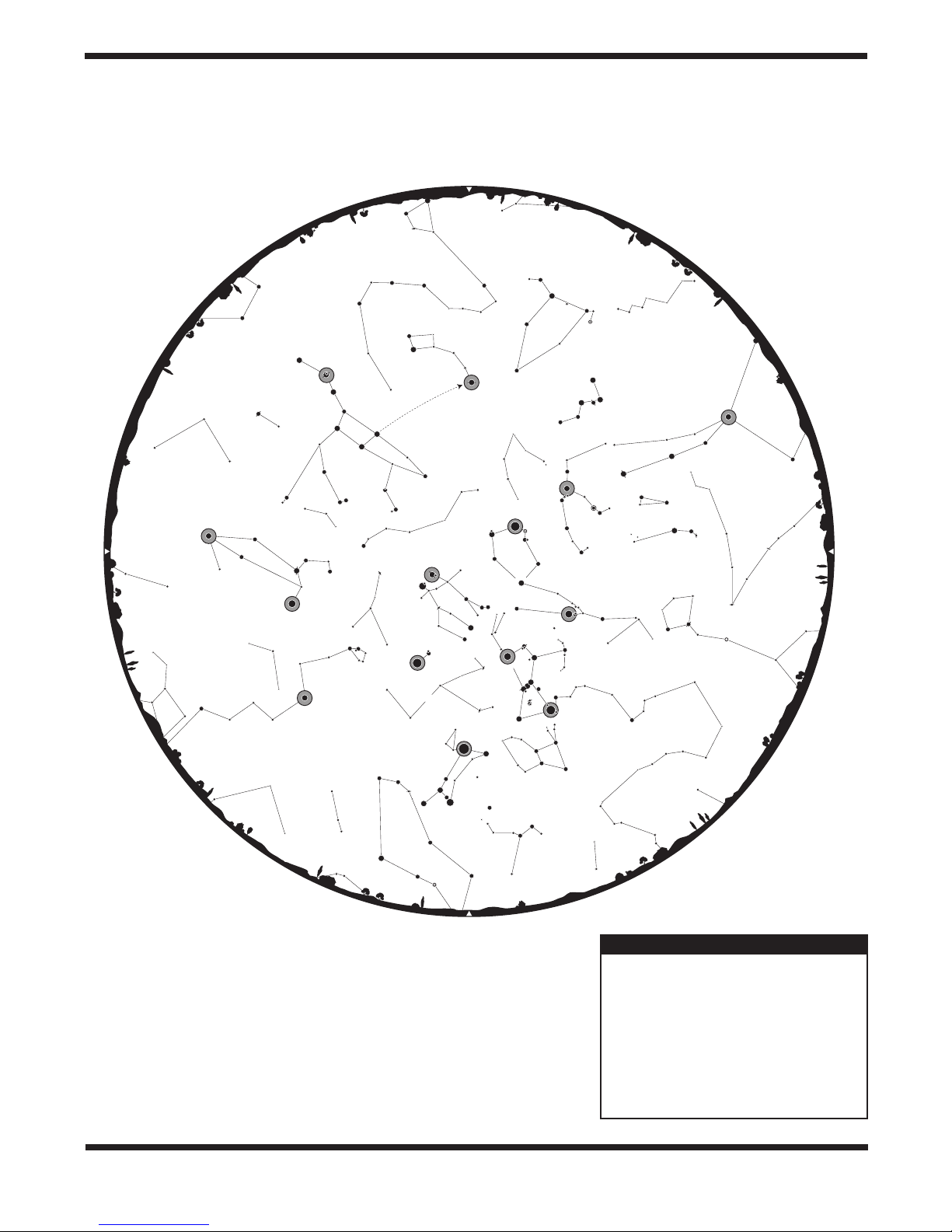
Appendix C – Sky Maps (for selection of alignment stars)
EAST
NORTH
Deneb
A
I
E
P
O
I
S
S
A
C
Y
G
N
U
S
C
E
P
H
E
U
S
Vega
LYRA
D
R
A
C
O
L
i
t
t
l
e
D
i
p
p
e
r
M
I
N
O
R
U
R
S
A
Rasalhague
H
E
R
C
U
L
E
S
O
P
H
I
U
C
H
U
S
Keystone
M
i
z
B
C
O
O
R
R
E
O
A
N
L
I
A
S
S
E
C
R
A
P
P
E
U
N
T
S
Arcturus
a
r
B
V
O
C
E
Ö
A
N
T
N
A
E
E
T
S
I
S
C
I
COMA
BERENICES
Denebola
s
r
e
t
Big Dipper
C
Mirfak
S
I
L
A
D
R
A
P
P
o
l
a
r
i
s
n
i
o
P
L
R
E
O
LEO
O
L
E
M
A
C
O
J
A
M
A
S
R
U
R
O
N
I
M
Regulus
A
C
a
l
l
e
p
a
C
LYNX
r
o
t
s
a
C
R
E
C
N
P
S
U
E
S
R
E
P
S
U
R
U
A
I
N
I
M
E
G
S
R
I
O
N
n
N
A
I
o
C
y
M
c
o
r
T
N
O
I
R
O
e
s
u
e
g
l
e
t
e
B
WEST
VIRGO
S
N
A
T
X
E
S
S
C
O
R
P
I
U
S
LIBRA
Spica
C
O
R
V
U
S
H
Y
D
R
A
C
E
N
T
A
U
R
U
S
C
R
A
R
T
E
A
I
L
T
N
A
VELA
d
r
a
h
p
l
A
A
R
D
Y
H
S
I
X
Y
P
L
I
W
S
O
R
E
C
O
N
O
M
PUPPIS
0
0
0
2
N
O
I
R
I
T
Sirius
SOUTH
SPRING
Early March 1:00 AM
Late March 12:00 AM
Early April 12:00 AM*
Late April 11:00 PM*
Early May 10:00 PM*
Late May 9:00 PM*
Early June 8:00 PM (dusk)*
*Daylight saving time
17
Page 18

NORTH
EAST
Mirfak
P
E
R
S
E
U
S
LYNX
P
I
S
C
E
S
Great Square of Pegasus
A
Q
U
A
R
I
U
S
S
C
A
C
Y
G
N
U
S
A
S
A
G
S
A
G
I
T
T
A
Altair
Q
U
I
L
A
I
T
T
A
R
I
U
U
S
Deneb
Albireo
S
C
U
Teapot
S
C
A
U
S
S
R
O
J
A
M
A
S
r
i
s
a
l
o
C
E
P
H
E
P
R
O
N
I
M
A
S
R
U
r
a
z
r
e
p
p
i
D
e
l
t
t
i
L
O
C
A
R
D
i
M
Vega
LYRA
V
U
L
P
E
C
U
L
A
R
Keystone
S
E
L
U
C
R
E
H
R
E
S
e
u
g
a
h
l
a
s
a
C
S
A
I
N
L
O
A
E
R
R
O
O
C
B
S
N
E
T
P
U
P
A
Pointers
Big Dipper
S
E
T
Ö
O
B
R
U
I
C
I
T
S
A
E
N
A
C
s
u
r
u
t
c
r
A
R
O
N
I
M
O
E
L
LEO
N
E
V
a
l
o
b
e
S
E
C
A
I
M
N
E
O
R
C
E
B
n
e
D
WEST
VIRGO
E
M
L
O
A
P
C
A
R
D
A
L
I
Spica
O
P
H
I
U
C
H
S
T
U
M
O
R
O
T
R
A
S
E
R
P
E
C
A
U
D
N
A
L
I
S
T
E
L
E
S
C
O
U
I
P
U
S
N
A
A
Antares
S
U
I
P
R
O
C
S
M
R
B
I
L
LUPUS
0
0
0
2
N
O
I
R
I
T
L
I
W
A
N
D
R
O
M
E
D
P
E
G
A
S
U
S
C
A
P
R
I
C
A
Alpheratz
E
Q
U
U
L
E
U
S
O
R
N
U
S
M
I
C
R
O
S
C
O
S
I
O
P
E
I
A
L
A
C
E
R
T
A
D
E
L
P
H
I
N
U
S
P
I
U
M
P
I
S
C
E
S
18
SOUTH
SUMMER
Early June 2:00 AM*
Late June 1:00 AM*
Early July 12:00 AM*
Late July 11:00 PM*
Early August 10:00 PM*
Late August 9:00 PM*
Early September 8:00 PM (dusk)*
*Daylight saving time
Page 19

EAST
NORTH
U
R
S
A
M
A
J
O
R
Pointers
LYNX
R
O
N
I
M
A
S
R
P
o
l
a
r
C
A
h
p
l
A
Great Square
of Pegasus
Q
A
U
S
U
E
z
t
a
r
e
S
U
I
R
A
U
a
m
o
F
S
I
P
G
E
M
I
N
I
A
l
B
e
t
e
ORION
l
g
e
u
s
e
E
d
e
b
a
r
a
n
Hyades
T
A
U
R
U
S
R
I
D
A
N
U
S
FORNAX
e
l
l
a
P
E
R
S
E
U
S
CETUS
C
a
p
A
R
I
E
S
A
L
I
S
M
i
r
f
a
k
Algol
T
R
I
A
N
G
U
L
U
M
P
H
O
E
C
A
M
E
L
O
P
A
R
D
P
I
S
C
E
N
I
X
i
s
S
S
I
O
P
E
I
A
A
N
D
R
O
M
E
D
A
S
S
C
U
L
P
T
O
R
Big Dipper
M
i
z
a
r
O
r
e
H
P
h
l
C
C
p
p
i
E
P
a
S
I
A
D
C
E
u
A
R
e
l
t
t
D
i
L
S
Keystone
E
L
U
C
R
E
H
b
e
n
e
D
A
T
R
E
C
A
L
S
U
S
A
G
S
U
E
L
U
U
Q
E
t
S
U
N
I
R
T
S
U
GRUS
Vega
Rosalhague
S
S
U
N
G
Y
C
D
M
LYRA
o
e
r
i
b
l
A
A
L
U
C
E
P
L
U
V
A
T
T
I
G
A
S
S
U
N
I
H
P
L
E
Altair
AQUILA
I
G
A
S
S
U
N
R
O
C
I
R
P
A
C
M
U
I
P
O
C
S
O
R
C
I
0
0
0
2
N
O
I
R
I
T
L
I
W
U
H
C
U
I
H
P
O
WEST
SERPENS
CAUDA
SCUTUM
S
U
I
R
A
T
T
SOUTH
AUTUMN
Early September 2:00 AM*
Late September 1:00 AM*
Early October 12:00 AM*
Late October 11:00 PM*
Early November 9:00 PM
Late November 8:00 PM
Early December 7:00 PM
*Daylight saving time
19
Page 20
EAST
VIRGO
NORTH
S
U
N
G
Y
C
H
E
R
C
U
L
E
S
B
O
Ö
T
E
S
M
i
z
a
U
R
S
A
M
A
L
E
O
M
I
N
O
R
Regulus
A
l
p
H
Y
D
R
A
r
Big Dipper
C
A
N
C
E
R
h
a
r
d
VENATICI
CANES
B
E
R
C
E
O
N
M
I
C
A
E
S
D
e
n
e
b
o
l
a
C
R
A
T
E
R
J
O
R
LEO
S
E
X
T
A
N
S
D
R
A
C
O
L
i
t
t
l
e
D
i
p
p
e
r
M
I
N
O
R
U
R
S
A
s
r
e
t
n
i
o
P
LYNX
C
a
s
t
o
r
P
o
l
l
u
x
P
r
G
o
E
M
c
I
N
y
o
n
C
A
M
N
I
I
N
S
O
R
M
O
N
O
C
E
R
O
S
I
S
I
B
Sirius
s
L
A
e
t
e
S
U
E
H
P
E
C
A
T
R
E
C
A
L
P
o
l
a
A
r
i
I
E
P
O
I
S
S
A
D
R
A
P
O
L
E
a
l
l
e
p
a
C
N
O
I
R
O
e
s
u
e
g
l
C
M
A
C
k
a
f
r
i
M
r
a
b
e
d
l
A
M
Algol
S
U
E
S
R
E
P
n
a
Hyades
S
U
R
U
A
T
Rigel
A
D
E
M
O
R
D
N
A
U
L
U
G
N
A
I
R
T
E
S
E
I
R
A
S
U
N
A
D
I
R
S
U
S
A
G
E
P
z
t
a
r
e
Great Square of Pegasus
h
p
l
A
S
E
C
S
I
P
WEST
Mira
CETUS
P
A
N
T
L
I
A
Y
X
I
20
S
U
P
E
S
I
N
A
C
R
O
J
A
S
VELA
PUPPIS
M
Adhara
C
L
A
B
M
U
L
O
M
U
L
E
A
C
O
I
R
I
T
L
I
W
FORNAX
0
0
0
2
N
SOUTH
WINTER
Early December 2:00 AM
Late December 1:00 AM
Early January 12:00 AM
Late January 11:00 PM
Early February 10:00 PM
Late February 9:00 PM
Early March 8:00 PM
Page 21

Specifications
SynScan GoTo
Object Database 42,900 objects
Object catalogs Messier, NGC, IC, SAO,
Caldwell, Double Star,
Variable Star, Named Star,
Planets
Motor type DC Servo
Resolution: 0.8923 arcsec
Slew Speeds Rate 0 = 1.0x (sidereal)
Rate 1 = 2.0x
Rate 2 = 8x
Rate 3 = 16x
Rate 4 = 32x
Rate 5 = 200x
Rate 6 = 400x
Rate 7 = 600x
Rate 8 = 800x
Rate 9 = 1000x
Tracking Rates Sidereal, Lunar, Solar
Hand controller Double line, 16-character LCD;
19 fiber optic backlit buttons
Alignment method Brightest Star, Two Star
Ports RS-232 on Hand Controller
Pointing Accuracy Up to 10 arc-minutes
Power Requirements: 12V DC (11-15V), 1A (Tip
positive)
Battery Pack Requires 8 AA batteries (not
included)
StarSeeker III 102mm Refractor
Objective Lens 102mm diameter doublet
Focal Length 660mm
Focal Ratio f/6.5
Focuser 1.25" Rack-and-Pinion
Lens Coatings Multi-coated
Eyepieces 25mm & 10mm Explorer II
Magnification with
supplied Eyepieces 26.4x, 66x
Diagonal Star diagonal, 90-degree, mirror
Tube Length 24.5"
Tube Material Aluminum
Weight, assembled: 13.4 lbs.
StarSeeker III 114mm Reflector
Primary Mirror: 130mm diameter, parabolic
Focal Length: 500mm
Focal Ratio: f/4.4
Focuser: 1 25" Rack and Pinion
Mirror Coatings: Aluminum with SiO2 overcoat
Eyepieces: 25mm & 10mm Explorer II
Magnification with
supplied Eyepieces 20x, 50x
Tube Length: 16.5"
Tube Material: Rolled steel
Weight, assembled: 12.4 lbs.
StarSeeker III 130mm Reflector
Primary Mirror: 130mm diameter, parabolic,
Focal Length: 650mm
Focal Ratio: f/5
Focuser: 1.25" Rack and Pinion
Mirror Coatings: Aluminum with SiO2 overcoat
Eyepieces: 25mm & 10mm Explorer II
Magnification with
supplied Eyepieces 26x, 65x
Tube Length: 24.25"
Tube Material: Seamed steel
Weight, assembled: 16.1 lbs.
Input Voltage: 12V DC
StarSeeker III 90mm Mak-Cass
Primary Mirror: 90mm diameter, spherical
Focal Length: 1250mm
Focal Ratio: f/13.9
Focuser: Internal, helical knob
Mirror Coatings: Aluminum with SiO2 overcoat
Eyepieces: 25mm & 10mm Explorer II
Magnification with
supplied Eyepieces 50x, 125x
Tube Length: 10.25"
Tube Material: Aluminum
Weight, assembled: 10.7 lbs.
Input Voltage: 12V DC
21
Page 22

StarSeeker III 102mm Mak-Cass
Primary Mirror: 102mm diameter, spherical
Focal Length: 1300mm
Focal Ratio: f/12.7
Focuser: Internal, helical knob
Mirror Coatings: Aluminum with SiO2 overcoat
Eyepieces: 25mm & 10mm Explorer II
Magnification with
supplied Eyepieces 52x, 130x
Tube Length: 12.5"
Tube Material: Aluminum
Weight, assembled: 13.4 lbs.
Input Voltage: 12V DC
StarSeeker III 127mm Mak-Cass
Primary Mirror: 127mm diameter, spherical
Focal Length: 1540mm
Focal Ratio: f/12.1
Focuser: Internal, helical knob
Mirror Coatings: Aluminum with SiO2 overcoat
Eyepieces: 25mm & 10mm Explorer II
Magnification with
supplied Eyepieces 61.6x, 154x
Tube Length: 14.5"
Tube Material: Aluminum
Weight, assembled: 16.7 lbs.
Input Voltage: 12V DC
One-Year Limited Warranty
This Orion product is warranted against defects in materials or workmanship for a period of one year
from the date of purchase. This warranty is for the benefit of the original retail purchaser only. During this
warranty period Orion Telescopes & Binoculars will repair or replace, at Orion’s option, any warranted
instrument that proves to be defective, provided it is returned postage paid. Proof of purchase (such as a
copy of the original receipt) is required. This warranty is only valid in the country of purchase.
This warranty does not apply if, in Orion’s judgment, the instrument has been abused, mishandled, or
modified, nor does it apply to normal wear and tear. This warranty gives you specific legal rights. It is not
intended to remove or restrict your other legal rights under applicable local consumer law; your state or
national statutory consumer rights governing the sale of consumer goods remain fully applicable.
For further warranty information, please visit www.OrionTelescopes.com/warranty.
Orion Telescopes & Binoculars
89 Hangar Way, Watsonville CA 95076
Customer Support Help Line (800) 676-1343 • Day or Evening
© Copyright 2014 Orion Telescopes & Binoculars
22
 Loading...