

Page 1
ORiNOCO AP-600 Access Point
User Guide
Page 2

2
Copyright
© 2003-2004 Proxim Corporation. All rights reserved. Covered by one or more of the following U.S. patents:
5,231,634; 5,875,179; 6,006,090; 5,809,060; 6,075,812; 5,077,753. This user’s guide and the software described in it
are copyrighted with all rights reserved. No part of this publication may be reproduced, transmitted, transcribed, stored
in a retrieval system, or translated into any language in any form by any means without the written permission of
Proxim Corporation.
Trademarks
ORiNOCO is a registered trademark, and Proxim, and the Proxim logo are trademarks of Proxim Corporation. All other
trademarks mentioned herein are the property of their respective owners.
OpenSSL License Note
This product contains software developed by the OpenSSL Project for use in the OpenSSL Toolkit (http://
www.openssl.org/) and that is subject to the following copyright and conditions:
Copyright (c) 1998-2002 The OpenSSL Project. All rights reserved.
The names "OpenSSL Toolkit" and "OpenSSL Project" must not be used to refer to, endorse, or promote the products
or for any other purpose related to the products without prior written permission. For written permission, please contact
[email protected].
THIS SOFTWARE IS PROVIDED BY THE OPENSSL PROJECT “AS IS” AND ANY EXPRESSED OR IMPLIED
WARRANTIES, INCLUDING, BUT NOT LIMITED TO, THE IMPLIED WARRANTIES OF MERCHANTABILITY AND
FITNESS FOR A PARTICULAR PURPOSE ARE DISCLAIMED. IN NO EVENT SHALL THE OPENSSL PROJECT
OR ITS CONTRIBUTORS BE LIABLE FOR ANY DIRECT, INDIRECT, INCIDENTAL, SPECIAL, EXEMPLARY, OR
CONSEQUENTIAL DAMAGES (INCLUDING, BUT NOT LIMITED TO, PROCUREMENT OF SUBSTITUTE GOODS
OR SERVICES; LOSS OF USE, DATA, OR PROFITS; OR BUSINESS INTERRUPTION) HOWEVER CAUSED AND
ON ANY THEORY OF LIABILITY, WHETHER IN CONTRACT, STRICT LIABILITY, OR TORT (INCLUDING
NEGLIGENCE OR OTHERWISE) ARISING IN ANY WAY OUT OF THE USE OF THIS SOFTWARE, EVEN IF
ADVISED OF THE POSSIBILITY OF SUCH DAMAGE.
ORiNOCO AP-600 User’s Guide
Software v2.5.2
P/N 68667 R1 October 2004
Page 3

3
Contents
1 Introduction . . . . . . . . . . . . . . . . . . . . . . . . . . . . . . . . . . . . . . . . . . . . . . . . . . . .12
Document Conventions . . . . . . . . . . . . . . . . . . . . . . . . . . . . . . . . . . . . . . . . . . . . . . . . . 12
Introduction to Wireless Networking . . . . . . . . . . . . . . . . . . . . . . . . . . . . . . . . . . . . . . . . 12
Guidelines for Roaming . . . . . . . . . . . . . . . . . . . . . . . . . . . . . . . . . . . . . . . . . . . . . . . . . . . . . . 13
IEEE 802.11 Specifications . . . . . . . . . . . . . . . . . . . . . . . . . . . . . . . . . . . . . . . . . . . . . . . 14
Management and Monitoring Capabilities . . . . . . . . . . . . . . . . . . . . . . . . . . . . . . . . . . . 14
HTTP/HTTPS Interface . . . . . . . . . . . . . . . . . . . . . . . . . . . . . . . . . . . . . . . . . . . . . . . . . . . . . . 14
Command Line Interface . . . . . . . . . . . . . . . . . . . . . . . . . . . . . . . . . . . . . . . . . . . . . . . . . . . . . 14
SNMP Management . . . . . . . . . . . . . . . . . . . . . . . . . . . . . . . . . . . . . . . . . . . . . . . . . . . . . . . . 15
SNMPv3 Secure Management . . . . . . . . . . . . . . . . . . . . . . . . . . . . . . . . . . . . . . . . . . . . . . 15
2 Getting Started . . . . . . . . . . . . . . . . . . . . . . . . . . . . . . . . . . . . . . . . . . . . . . . . . .16
Prerequisites . . . . . . . . . . . . . . . . . . . . . . . . . . . . . . . . . . . . . . . . . . . . . . . . . . . . . . . . . . 16
Product Package . . . . . . . . . . . . . . . . . . . . . . . . . . . . . . . . . . . . . . . . . . . . . . . . . . . . . . 17
5 GHz Antenna Adapter or AP-2000 11a Upgrade Kit. . . . . . . . . . . . . . . . . . . . . . . . . . . . . . . 17
System Requirements . . . . . . . . . . . . . . . . . . . . . . . . . . . . . . . . . . . . . . . . . . . . . . . . . . 17
Hardware Installation . . . . . . . . . . . . . . . . . . . . . . . . . . . . . . . . . . . . . . . . . . . . . . . . . . . 18
AP-2000 with Active Ethernet . . . . . . . . . . . . . . . . . . . . . . . . . . . . . . . . . . . . . . . . . . . . . . . . . 18
AP-2000 with Power Supply . . . . . . . . . . . . . . . . . . . . . . . . . . . . . . . . . . . . . . . . . . . . . . . . . . 19
5 GHz or AP-2000 11a Upgrade Kit. . . . . . . . . . . . . . . . . . . . . . . . . . . . . . . . . . . . . . . . . . . . . 22
Initialization . . . . . . . . . . . . . . . . . . . . . . . . . . . . . . . . . . . . . . . . . . . . . . . . . . . . . . . . . . . 24
ScanTool . . . . . . . . . . . . . . . . . . . . . . . . . . . . . . . . . . . . . . . . . . . . . . . . . . . . . . . . . . . . . . . . . 24
ScanTool Instructions . . . . . . . . . . . . . . . . . . . . . . . . . . . . . . . . . . . . . . . . . . . . . . . . . . . . . 24
Setup Wizard . . . . . . . . . . . . . . . . . . . . . . . . . . . . . . . . . . . . . . . . . . . . . . . . . . . . . . . . . . . . . . 26
Setup Wizard Instructions. . . . . . . . . . . . . . . . . . . . . . . . . . . . . . . . . . . . . . . . . . . . . . . . . . 26
Download the Latest Software . . . . . . . . . . . . . . . . . . . . . . . . . . . . . . . . . . . . . . . . . . . . 29
Setup your TFTP Server . . . . . . . . . . . . . . . . . . . . . . . . . . . . . . . . . . . . . . . . . . . . . . . . . . . . . 30
Download Updates from your TFTP Server using the Web Interface . . . . . . . . . . . . . . . . . . . 30
Download Updates from your TFTP Server using the CLI Interface . . . . . . . . . . . . . . . . . . . . 31
Additional Hardware Features . . . . . . . . . . . . . . . . . . . . . . . . . . . . . . . . . . . . . . . . . . . . 31
Installing the AP in a Plenum. . . . . . . . . . . . . . . . . . . . . . . . . . . . . . . . . . . . . . . . . . . . . . . . . . 31
Installing/Removing the Metal Faceplate . . . . . . . . . . . . . . . . . . . . . . . . . . . . . . . . . . . . . . 31
Active Ethernet . . . . . . . . . . . . . . . . . . . . . . . . . . . . . . . . . . . . . . . . . . . . . . . . . . . . . . . . . . . . 32
Page 4

4
Contents
LED Indicators . . . . . . . . . . . . . . . . . . . . . . . . . . . . . . . . . . . . . . . . . . . . . . . . . . . . . . . . . . . . . 32
3 Viewing Status Information . . . . . . . . . . . . . . . . . . . . . . . . . . . . . . . . . . . . . . . . 34
Logging into the HTTP Interface . . . . . . . . . . . . . . . . . . . . . . . . . . . . . . . . . . . . . . . . . . . 34
System Status . . . . . . . . . . . . . . . . . . . . . . . . . . . . . . . . . . . . . . . . . . . . . . . . . . . . . . . . . 35
4 Performing Advanced Configuration . . . . . . . . . . . . . . . . . . . . . . . . . . . . . . . .36
Configuring the AP Using the HTTP/HTTPS Interface . . . . . . . . . . . . . . . . . . . . . . . . . . 36
System . . . . . . . . . . . . . . . . . . . . . . . . . . . . . . . . . . . . . . . . . . . . . . . . . . . . . . . . . . . . . . 38
Dynamic DNS Support. . . . . . . . . . . . . . . . . . . . . . . . . . . . . . . . . . . . . . . . . . . . . . . . . . . . . . . 38
Access Point System Naming Convention . . . . . . . . . . . . . . . . . . . . . . . . . . . . . . . . . . . . . 38
Network . . . . . . . . . . . . . . . . . . . . . . . . . . . . . . . . . . . . . . . . . . . . . . . . . . . . . . . . . . . . . . 39
IP Configuration . . . . . . . . . . . . . . . . . . . . . . . . . . . . . . . . . . . . . . . . . . . . . . . . . . . . . . . . . . . . 39
DHCP Server . . . . . . . . . . . . . . . . . . . . . . . . . . . . . . . . . . . . . . . . . . . . . . . . . . . . . . . . . . . . . . 40
Link Integrity . . . . . . . . . . . . . . . . . . . . . . . . . . . . . . . . . . . . . . . . . . . . . . . . . . . . . . . . . . . . . . 41
Interfaces . . . . . . . . . . . . . . . . . . . . . . . . . . . . . . . . . . . . . . . . . . . . . . . . . . . . . . . . . . . . 42
Operational Mode . . . . . . . . . . . . . . . . . . . . . . . . . . . . . . . . . . . . . . . . . . . . . . . . . . . . . . . . . . 43
Operational Mode Selection . . . . . . . . . . . . . . . . . . . . . . . . . . . . . . . . . . . . . . . . . . . . . . . . 43
8Wireless-A and Wireless-B . . . . . . . . . . . . . . . . . . . . . . . . . . . . . . . . . . . . . . . . . . . . . . . . . . 43
Wireless A (802.11a) . . . . . . . . . . . . . . . . . . . . . . . . . . . . . . . . . . . . . . . . . . . . . . . . . . . . . 43
Wireless (802.11b) . . . . . . . . . . . . . . . . . . . . . . . . . . . . . . . . . . . . . . . . . . . . . . . . . . . . . . . 45
Wireless (802.11b/g). . . . . . . . . . . . . . . . . . . . . . . . . . . . . . . . . . . . . . . . . . . . . . . . . . . . . . 48
Wireless Distribution System (WDS) . . . . . . . . . . . . . . . . . . . . . . . . . . . . . . . . . . . . . . . . . 49
Ethernet . . . . . . . . . . . . . . . . . . . . . . . . . . . . . . . . . . . . . . . . . . . . . . . . . . . . . . . . . . . . . . . . . . 52
Management . . . . . . . . . . . . . . . . . . . . . . . . . . . . . . . . . . . . . . . . . . . . . . . . . . . . . . . . . . 53
Passwords . . . . . . . . . . . . . . . . . . . . . . . . . . . . . . . . . . . . . . . . . . . . . . . . . . . . . . . . . . . . . . . . 53
IP Access Table . . . . . . . . . . . . . . . . . . . . . . . . . . . . . . . . . . . . . . . . . . . . . . . . . . . . . . . . . . . . 53
Services . . . . . . . . . . . . . . . . . . . . . . . . . . . . . . . . . . . . . . . . . . . . . . . . . . . . . . . . . . . . . . . . . . 54
Secure Management . . . . . . . . . . . . . . . . . . . . . . . . . . . . . . . . . . . . . . . . . . . . . . . . . . . . . 54
SNMP Settings . . . . . . . . . . . . . . . . . . . . . . . . . . . . . . . . . . . . . . . . . . . . . . . . . . . . . . . . . . 54
HTTP Access . . . . . . . . . . . . . . . . . . . . . . . . . . . . . . . . . . . . . . . . . . . . . . . . . . . . . . . . . . . 54
HTTPS Access . . . . . . . . . . . . . . . . . . . . . . . . . . . . . . . . . . . . . . . . . . . . . . . . . . . . . . . . . . 54
Telnet Configuration Settings . . . . . . . . . . . . . . . . . . . . . . . . . . . . . . . . . . . . . . . . . . . . . . . 56
Secure Shell (SSH) Settings . . . . . . . . . . . . . . . . . . . . . . . . . . . . . . . . . . . . . . . . . . . . . . . 56
Serial Configuration Settings . . . . . . . . . . . . . . . . . . . . . . . . . . . . . . . . . . . . . . . . . . . . . . . 58
RADIUS Based Management Access . . . . . . . . . . . . . . . . . . . . . . . . . . . . . . . . . . . . . . . . 58
Automatic Configuration (AutoConfig) . . . . . . . . . . . . . . . . . . . . . . . . . . . . . . . . . . . . . . . . . . . 59
Auto Configuration and the CLI Batch File . . . . . . . . . . . . . . . . . . . . . . . . . . . . . . . . . . . . . 59
Hardware Configuration Reset (CHRP) . . . . . . . . . . . . . . . . . . . . . . . . . . . . . . . . . . . . . . . . . . 62
Configuration Reset via Serial Port During Bootup . . . . . . . . . . . . . . . . . . . . . . . . . . . . . . 62
Configuring Hardware Configuration Reset . . . . . . . . . . . . . . . . . . . . . . . . . . . . . . . . . . . . 63
Page 5

5
Contents
Procedure to Reset Configuration via the Serial Interface . . . . . . . . . . . . . . . . . . . . . . . . . 63
Filtering . . . . . . . . . . . . . . . . . . . . . . . . . . . . . . . . . . . . . . . . . . . . . . . . . . . . . . . . . . . . . . 64
Ethernet Protocol . . . . . . . . . . . . . . . . . . . . . . . . . . . . . . . . . . . . . . . . . . . . . . . . . . . . . . . . . . . 64
Static MAC. . . . . . . . . . . . . . . . . . . . . . . . . . . . . . . . . . . . . . . . . . . . . . . . . . . . . . . . . . . . . . . . 64
Static MAC Filter Examples . . . . . . . . . . . . . . . . . . . . . . . . . . . . . . . . . . . . . . . . . . . . . . . . 66
Advanced. . . . . . . . . . . . . . . . . . . . . . . . . . . . . . . . . . . . . . . . . . . . . . . . . . . . . . . . . . . . . . . . . 67
TCP/UDP Port . . . . . . . . . . . . . . . . . . . . . . . . . . . . . . . . . . . . . . . . . . . . . . . . . . . . . . . . . . . . . 67
Adding TCP/UDP Port Filters . . . . . . . . . . . . . . . . . . . . . . . . . . . . . . . . . . . . . . . . . . . . . . . 67
Editing TCP/UDP Port Filters . . . . . . . . . . . . . . . . . . . . . . . . . . . . . . . . . . . . . . . . . . . . . . . 68
Alarms . . . . . . . . . . . . . . . . . . . . . . . . . . . . . . . . . . . . . . . . . . . . . . . . . . . . . . . . . . . . . . . 69
Groups . . . . . . . . . . . . . . . . . . . . . . . . . . . . . . . . . . . . . . . . . . . . . . . . . . . . . . . . . . . . . . . . . . . 69
Severity Levels . . . . . . . . . . . . . . . . . . . . . . . . . . . . . . . . . . . . . . . . . . . . . . . . . . . . . . . . . . 72
Alarm Host Table . . . . . . . . . . . . . . . . . . . . . . . . . . . . . . . . . . . . . . . . . . . . . . . . . . . . . . . . . . . 72
Syslog . . . . . . . . . . . . . . . . . . . . . . . . . . . . . . . . . . . . . . . . . . . . . . . . . . . . . . . . . . . . . . . . . . . 72
Setting Syslog Event Notifications . . . . . . . . . . . . . . . . . . . . . . . . . . . . . . . . . . . . . . . . . . . 72
Configuring Syslog Event Notifications. . . . . . . . . . . . . . . . . . . . . . . . . . . . . . . . . . . . . . . . 72
Syslog Messages . . . . . . . . . . . . . . . . . . . . . . . . . . . . . . . . . . . . . . . . . . . . . . . . . . . . . . . . 73
Rogue Access Point Detection (RAD) . . . . . . . . . . . . . . . . . . . . . . . . . . . . . . . . . . . . . . . . . . . 74
RAD Configuration Requirements . . . . . . . . . . . . . . . . . . . . . . . . . . . . . . . . . . . . . . . . . . . 74
Configuring RAD. . . . . . . . . . . . . . . . . . . . . . . . . . . . . . . . . . . . . . . . . . . . . . . . . . . . . . . . . 75
Bridge . . . . . . . . . . . . . . . . . . . . . . . . . . . . . . . . . . . . . . . . . . . . . . . . . . . . . . . . . . . . . . . 76
Spanning Tree . . . . . . . . . . . . . . . . . . . . . . . . . . . . . . . . . . . . . . . . . . . . . . . . . . . . . . . . . . . . . 76
Storm Threshold . . . . . . . . . . . . . . . . . . . . . . . . . . . . . . . . . . . . . . . . . . . . . . . . . . . . . . . . . . . 76
Intra BSS . . . . . . . . . . . . . . . . . . . . . . . . . . . . . . . . . . . . . . . . . . . . . . . . . . . . . . . . . . . . . . . . . 76
Packet Forwarding (Pkt Fwd) . . . . . . . . . . . . . . . . . . . . . . . . . . . . . . . . . . . . . . . . . . . . . . . . . 77
QoS (Quality of Service) . . . . . . . . . . . . . . . . . . . . . . . . . . . . . . . . . . . . . . . . . . . . . . . . . 77
RADIUS Profiles . . . . . . . . . . . . . . . . . . . . . . . . . . . . . . . . . . . . . . . . . . . . . . . . . . . . . . . 78
RADIUS Servers per Authentication Mode and per VLAN . . . . . . . . . . . . . . . . . . . . . . . . . . . 78
RADIUS-based VLAN Assignment . . . . . . . . . . . . . . . . . . . . . . . . . . . . . . . . . . . . . . . . . . . 79
RADIUS Servers Enforcing VLAN Access Control . . . . . . . . . . . . . . . . . . . . . . . . . . . . . . . 79
Configuring RADIUS Profiles. . . . . . . . . . . . . . . . . . . . . . . . . . . . . . . . . . . . . . . . . . . . . . . . . . 79
Adding or Modifying a RADIUS Server Profile . . . . . . . . . . . . . . . . . . . . . . . . . . . . . . . . . . 80
MAC Access Control Via RADIUS Authentication . . . . . . . . . . . . . . . . . . . . . . . . . . . . . . . . . . 81
802.1x Authentication using RADIUS . . . . . . . . . . . . . . . . . . . . . . . . . . . . . . . . . . . . . . . . . . . 81
RADIUS Accounting . . . . . . . . . . . . . . . . . . . . . . . . . . . . . . . . . . . . . . . . . . . . . . . . . . . . . . . . 82
Session Length. . . . . . . . . . . . . . . . . . . . . . . . . . . . . . . . . . . . . . . . . . . . . . . . . . . . . . . . . . 82
SSID/VLAN/Security . . . . . . . . . . . . . . . . . . . . . . . . . . . . . . . . . . . . . . . . . . . . . . . . . . . . 83
Management VLAN . . . . . . . . . . . . . . . . . . . . . . . . . . . . . . . . . . . . . . . . . . . . . . . . . . . . . . . . . 83
VLAN Overview . . . . . . . . . . . . . . . . . . . . . . . . . . . . . . . . . . . . . . . . . . . . . . . . . . . . . . . . . 83
Enabling/Disabling VLAN Protocol . . . . . . . . . . . . . . . . . . . . . . . . . . . . . . . . . . . . . . . . . . . 85
MAC Access . . . . . . . . . . . . . . . . . . . . . . . . . . . . . . . . . . . . . . . . . . . . . . . . . . . . . . . . . . . . . . 86
Page 6

6
Contents
Configuring MAC Access . . . . . . . . . . . . . . . . . . . . . . . . . . . . . . . . . . . . . . . . . . . . . . . . . . 86
Security Profiles. . . . . . . . . . . . . . . . . . . . . . . . . . . . . . . . . . . . . . . . . . . . . . . . . . . . . . . . . . . . 87
WEP Encryption . . . . . . . . . . . . . . . . . . . . . . . . . . . . . . . . . . . . . . . . . . . . . . . . . . . . . . . . . 87
802.1x Authentication . . . . . . . . . . . . . . . . . . . . . . . . . . . . . . . . . . . . . . . . . . . . . . . . . . . . . 87
Wi-Fi Protected Access (WPA). . . . . . . . . . . . . . . . . . . . . . . . . . . . . . . . . . . . . . . . . . . . . . 88
Authentication Protocol Hierarchy . . . . . . . . . . . . . . . . . . . . . . . . . . . . . . . . . . . . . . . . . . . 89
VLANs and Security Profiles . . . . . . . . . . . . . . . . . . . . . . . . . . . . . . . . . . . . . . . . . . . . . . . 89
Configuring Security Profiles . . . . . . . . . . . . . . . . . . . . . . . . . . . . . . . . . . . . . . . . . . . . . . . 90
Wireless-A and Wireless-B . . . . . . . . . . . . . . . . . . . . . . . . . . . . . . . . . . . . . . . . . . . . . . . . . . . 93
Adding or Modifying an SSID/VLAN with VLAN Protocol Disabled . . . . . . . . . . . . . . . . . . 93
Adding or Modifying an SSID/VLAN with VLAN Protocol Enabled. . . . . . . . . . . . . . . . . . . 96
Broadcast SSID and Closed System . . . . . . . . . . . . . . . . . . . . . . . . . . . . . . . . . . . . . . . . . 99
5 Monitoring the AP-2000 . . . . . . . . . . . . . . . . . . . . . . . . . . . . . . . . . . . . . . . . . .100
Logging into the HTTP Interface . . . . . . . . . . . . . . . . . . . . . . . . . . . . . . . . . . . . . . . . . . 100
Version . . . . . . . . . . . . . . . . . . . . . . . . . . . . . . . . . . . . . . . . . . . . . . . . . . . . . . . . . . . . . 102
ICMP . . . . . . . . . . . . . . . . . . . . . . . . . . . . . . . . . . . . . . . . . . . . . . . . . . . . . . . . . . . . . . . 103
IP/ARP Table . . . . . . . . . . . . . . . . . . . . . . . . . . . . . . . . . . . . . . . . . . . . . . . . . . . . . . . . 103
Learn Table . . . . . . . . . . . . . . . . . . . . . . . . . . . . . . . . . . . . . . . . . . . . . . . . . . . . . . . . . . 104
IAPP . . . . . . . . . . . . . . . . . . . . . . . . . . . . . . . . . . . . . . . . . . . . . . . . . . . . . . . . . . . . . . . 104
RADIUS . . . . . . . . . . . . . . . . . . . . . . . . . . . . . . . . . . . . . . . . . . . . . . . . . . . . . . . . . . . . 105
Interfaces . . . . . . . . . . . . . . . . . . . . . . . . . . . . . . . . . . . . . . . . . . . . . . . . . . . . . . . . . . . 106
Station Statistics . . . . . . . . . . . . . . . . . . . . . . . . . . . . . . . . . . . . . . . . . . . . . . . . . . . . . . 107
Enabling and Viewing Station Statistics . . . . . . . . . . . . . . . . . . . . . . . . . . . . . . . . . . . . . . . . . 107
Refreshing Station Statistics . . . . . . . . . . . . . . . . . . . . . . . . . . . . . . . . . . . . . . . . . . . . . . . . . 107
Description of Station Statistics. . . . . . . . . . . . . . . . . . . . . . . . . . . . . . . . . . . . . . . . . . . . . 107
6 Performing Commands . . . . . . . . . . . . . . . . . . . . . . . . . . . . . . . . . . . . . . . . . .109
Logging into the HTTP Interface . . . . . . . . . . . . . . . . . . . . . . . . . . . . . . . . . . . . . . . . . . 109
Introduction to File Transfer via TFTP or HTTP . . . . . . . . . . . . . . . . . . . . . . . . . . . . . . 111
TFTP File Transfer Guidelines. . . . . . . . . . . . . . . . . . . . . . . . . . . . . . . . . . . . . . . . . . . . . . . . .111
HTTP File Transfer Guidelines . . . . . . . . . . . . . . . . . . . . . . . . . . . . . . . . . . . . . . . . . . . . . . . .111
Image Error Checking during File Transfer . . . . . . . . . . . . . . . . . . . . . . . . . . . . . . . . . . . . . . .111
Update AP via TFTP . . . . . . . . . . . . . . . . . . . . . . . . . . . . . . . . . . . . . . . . . . . . . . . . . . . 112
Update AP via HTTP . . . . . . . . . . . . . . . . . . . . . . . . . . . . . . . . . . . . . . . . . . . . . . . . . . 113
Retrieve File via TFTP . . . . . . . . . . . . . . . . . . . . . . . . . . . . . . . . . . . . . . . . . . . . . . . . . 115
Retrieve File via HTTP . . . . . . . . . . . . . . . . . . . . . . . . . . . . . . . . . . . . . . . . . . . . . . . . . 116
Reboot . . . . . . . . . . . . . . . . . . . . . . . . . . . . . . . . . . . . . . . . . . . . . . . . . . . . . . . . . . . . . 118
Reset . . . . . . . . . . . . . . . . . . . . . . . . . . . . . . . . . . . . . . . . . . . . . . . . . . . . . . . . . . . . . . 119
Page 7

7
Contents
Help Link . . . . . . . . . . . . . . . . . . . . . . . . . . . . . . . . . . . . . . . . . . . . . . . . . . . . . . . . . . . . 120
7 Troubleshooting the AP-2000 . . . . . . . . . . . . . . . . . . . . . . . . . . . . . . . . . . . . .121
Troubleshooting Concepts . . . . . . . . . . . . . . . . . . . . . . . . . . . . . . . . . . . . . . . . . . . . . . 121
Symptoms and Solutions . . . . . . . . . . . . . . . . . . . . . . . . . . . . . . . . . . . . . . . . . . . . . . . 122
Connectivity Issues . . . . . . . . . . . . . . . . . . . . . . . . . . . . . . . . . . . . . . . . . . . . . . . . . . . . . . . . 122
AP Unit Will Not Boot - No LED Activity . . . . . . . . . . . . . . . . . . . . . . . . . . . . . . . . . . . . . . 122
Serial Link Does Not Work . . . . . . . . . . . . . . . . . . . . . . . . . . . . . . . . . . . . . . . . . . . . . . . . 122
Ethernet Link Does Not Work . . . . . . . . . . . . . . . . . . . . . . . . . . . . . . . . . . . . . . . . . . . . . . 122
Basic Software Setup and Configuration Problems . . . . . . . . . . . . . . . . . . . . . . . . . . . . . . . . 122
Lost AP, Telnet, or SNMP Password. . . . . . . . . . . . . . . . . . . . . . . . . . . . . . . . . . . . . . . . . 122
Client Computer Cannot Connect. . . . . . . . . . . . . . . . . . . . . . . . . . . . . . . . . . . . . . . . . . . 122
AP Has Incorrect IP Address . . . . . . . . . . . . . . . . . . . . . . . . . . . . . . . . . . . . . . . . . . . . . . 122
HTTP (browser) or Telnet Interface Does Not Work . . . . . . . . . . . . . . . . . . . . . . . . . . . . . 123
HTML Help Files Do Not Appear . . . . . . . . . . . . . . . . . . . . . . . . . . . . . . . . . . . . . . . . . . . 123
Telnet CLI Does Not Work . . . . . . . . . . . . . . . . . . . . . . . . . . . . . . . . . . . . . . . . . . . . . . . . 123
TFTP Server Does Not Work . . . . . . . . . . . . . . . . . . . . . . . . . . . . . . . . . . . . . . . . . . . . . . 123
Client Connection Problems . . . . . . . . . . . . . . . . . . . . . . . . . . . . . . . . . . . . . . . . . . . . . . . . . 124
Client Software Finds No Connection. . . . . . . . . . . . . . . . . . . . . . . . . . . . . . . . . . . . . . . . 124
Client PC Card Does Not Work . . . . . . . . . . . . . . . . . . . . . . . . . . . . . . . . . . . . . . . . . . . . 124
Intermittent Loss of Connection . . . . . . . . . . . . . . . . . . . . . . . . . . . . . . . . . . . . . . . . . . . . 124
Client Does Not Receive an IP Address - Cannot Connect to Internet . . . . . . . . . . . . . . 124
VLAN Operation Issues . . . . . . . . . . . . . . . . . . . . . . . . . . . . . . . . . . . . . . . . . . . . . . . . . . . . . 124
Verifying Proper Operation of the VLAN Feature . . . . . . . . . . . . . . . . . . . . . . . . . . . . . . . 124
VLAN Workgroups . . . . . . . . . . . . . . . . . . . . . . . . . . . . . . . . . . . . . . . . . . . . . . . . . . . . . . 124
Active Ethernet (AE) . . . . . . . . . . . . . . . . . . . . . . . . . . . . . . . . . . . . . . . . . . . . . . . . . . . . . . . 125
The AP Does Not Work . . . . . . . . . . . . . . . . . . . . . . . . . . . . . . . . . . . . . . . . . . . . . . . . . . 125
There Is No Data Link. . . . . . . . . . . . . . . . . . . . . . . . . . . . . . . . . . . . . . . . . . . . . . . . . . . . 125
“Overload” Indications . . . . . . . . . . . . . . . . . . . . . . . . . . . . . . . . . . . . . . . . . . . . . . . . . . . 125
Recovery Procedures . . . . . . . . . . . . . . . . . . . . . . . . . . . . . . . . . . . . . . . . . . . . . . . . . . 125
Reset to Factory Default Procedure . . . . . . . . . . . . . . . . . . . . . . . . . . . . . . . . . . . . . . . . . . . 126
Forced Reload Procedure . . . . . . . . . . . . . . . . . . . . . . . . . . . . . . . . . . . . . . . . . . . . . . . . . . . 126
Download a New Image Using ScanTool . . . . . . . . . . . . . . . . . . . . . . . . . . . . . . . . . . . . . 127
Download a New Image Using the Bootloader CLI . . . . . . . . . . . . . . . . . . . . . . . . . . . . . 128
Setting IP Address using Serial Port . . . . . . . . . . . . . . . . . . . . . . . . . . . . . . . . . . . . . . . . . . . 129
Hardware and Software Requirements. . . . . . . . . . . . . . . . . . . . . . . . . . . . . . . . . . . . . . . 129
Attaching the Serial Port Cable. . . . . . . . . . . . . . . . . . . . . . . . . . . . . . . . . . . . . . . . . . . . . 129
Initializing the IP Address using CLI . . . . . . . . . . . . . . . . . . . . . . . . . . . . . . . . . . . . . . . . . 129
Related Applications . . . . . . . . . . . . . . . . . . . . . . . . . . . . . . . . . . . . . . . . . . . . . . . . . . . 131
RADIUS Authentication Server . . . . . . . . . . . . . . . . . . . . . . . . . . . . . . . . . . . . . . . . . . . . . . . 131
TFTP Server . . . . . . . . . . . . . . . . . . . . . . . . . . . . . . . . . . . . . . . . . . . . . . . . . . . . . . . . . . . . . 131
Page 8

8
Contents
A Using the Command Line Interface (CLI). . . . . . . . . . . . . . . . . . . . . . . . . . . . 132
General Notes . . . . . . . . . . . . . . . . . . . . . . . . . . . . . . . . . . . . . . . . . . . . . . . . . . . . . . . . 132
Prerequisite Skills and Knowledge . . . . . . . . . . . . . . . . . . . . . . . . . . . . . . . . . . . . . . . . . . . . 132
Notation Conventions . . . . . . . . . . . . . . . . . . . . . . . . . . . . . . . . . . . . . . . . . . . . . . . . . . . . . . 132
Important Terminology . . . . . . . . . . . . . . . . . . . . . . . . . . . . . . . . . . . . . . . . . . . . . . . . . . . . . . 132
Navigation and Special Keys . . . . . . . . . . . . . . . . . . . . . . . . . . . . . . . . . . . . . . . . . . . . . . . . . 133
CLI Error Messages. . . . . . . . . . . . . . . . . . . . . . . . . . . . . . . . . . . . . . . . . . . . . . . . . . . . . . . . 133
Command Line Interface (CLI) Variations . . . . . . . . . . . . . . . . . . . . . . . . . . . . . . . . . . . 133
Bootloader CLI. . . . . . . . . . . . . . . . . . . . . . . . . . . . . . . . . . . . . . . . . . . . . . . . . . . . . . . . . . . . 134
CLI Command Types . . . . . . . . . . . . . . . . . . . . . . . . . . . . . . . . . . . . . . . . . . . . . . . . . . 135
Operational CLI Commands . . . . . . . . . . . . . . . . . . . . . . . . . . . . . . . . . . . . . . . . . . . . . . . . . 135
? (List Commands) . . . . . . . . . . . . . . . . . . . . . . . . . . . . . . . . . . . . . . . . . . . . . . . . . . . . . . 135
done, exit, quit . . . . . . . . . . . . . . . . . . . . . . . . . . . . . . . . . . . . . . . . . . . . . . . . . . . . . . . . . 137
download . . . . . . . . . . . . . . . . . . . . . . . . . . . . . . . . . . . . . . . . . . . . . . . . . . . . . . . . . . . . . 137
help. . . . . . . . . . . . . . . . . . . . . . . . . . . . . . . . . . . . . . . . . . . . . . . . . . . . . . . . . . . . . . . . . . 137
history . . . . . . . . . . . . . . . . . . . . . . . . . . . . . . . . . . . . . . . . . . . . . . . . . . . . . . . . . . . . . . . . 138
passwd . . . . . . . . . . . . . . . . . . . . . . . . . . . . . . . . . . . . . . . . . . . . . . . . . . . . . . . . . . . . . . . 138
reboot . . . . . . . . . . . . . . . . . . . . . . . . . . . . . . . . . . . . . . . . . . . . . . . . . . . . . . . . . . . . . . . . 138
search. . . . . . . . . . . . . . . . . . . . . . . . . . . . . . . . . . . . . . . . . . . . . . . . . . . . . . . . . . . . . . . . 138
upload. . . . . . . . . . . . . . . . . . . . . . . . . . . . . . . . . . . . . . . . . . . . . . . . . . . . . . . . . . . . . . . . 139
Parameter Control Commands . . . . . . . . . . . . . . . . . . . . . . . . . . . . . . . . . . . . . . . . . . . . . . . 139
“show” CLI Command. . . . . . . . . . . . . . . . . . . . . . . . . . . . . . . . . . . . . . . . . . . . . . . . . . . . 139
“set” CLI Command . . . . . . . . . . . . . . . . . . . . . . . . . . . . . . . . . . . . . . . . . . . . . . . . . . . . . 139
Configuring Objects that Require Reboot . . . . . . . . . . . . . . . . . . . . . . . . . . . . . . . . . . . . . 140
“set” and “show” Command Examples . . . . . . . . . . . . . . . . . . . . . . . . . . . . . . . . . . . . . . . 140
Using Tables & User Strings . . . . . . . . . . . . . . . . . . . . . . . . . . . . . . . . . . . . . . . . . . . . . 142
Working with Tables. . . . . . . . . . . . . . . . . . . . . . . . . . . . . . . . . . . . . . . . . . . . . . . . . . . . . . . . 142
Using Strings . . . . . . . . . . . . . . . . . . . . . . . . . . . . . . . . . . . . . . . . . . . . . . . . . . . . . . . . . . . . . 143
Configuring the AP using CLI commands . . . . . . . . . . . . . . . . . . . . . . . . . . . . . . . . . . . 143
Log into the AP using HyperTerminal . . . . . . . . . . . . . . . . . . . . . . . . . . . . . . . . . . . . . . . . . . 143
Log into the AP using Telnet . . . . . . . . . . . . . . . . . . . . . . . . . . . . . . . . . . . . . . . . . . . . . . . . . 143
Set Basic Configuration Parameters using CLI Commands . . . . . . . . . . . . . . . . . . . . . 144
Set System Name, Location and Contact Information . . . . . . . . . . . . . . . . . . . . . . . . . . . 144
Set Static IP Address for the AP. . . . . . . . . . . . . . . . . . . . . . . . . . . . . . . . . . . . . . . . . . . . 144
Change Passwords . . . . . . . . . . . . . . . . . . . . . . . . . . . . . . . . . . . . . . . . . . . . . . . . . . . . . 144
Set Network Names for the Wireless Interface. . . . . . . . . . . . . . . . . . . . . . . . . . . . . . . . . 145
Enable and Configure TX Power Control for the Wireless Interface(s) . . . . . . . . . . . . . . 145
Configure SSID (Network Name) and VLAN Pairs, and Profiles . . . . . . . . . . . . . . . . . . . 145
Download an AP Configuration File from your TFTP Server . . . . . . . . . . . . . . . . . . . . . . 147
Backup your AP Configuration File. . . . . . . . . . . . . . . . . . . . . . . . . . . . . . . . . . . . . . . . . . 147
Page 9

9
Contents
Set up Auto Configuration . . . . . . . . . . . . . . . . . . . . . . . . . . . . . . . . . . . . . . . . . . . . . . . . 147
Other Network Settings . . . . . . . . . . . . . . . . . . . . . . . . . . . . . . . . . . . . . . . . . . . . . . . . . 147
Configure the AP as a DHCP Server . . . . . . . . . . . . . . . . . . . . . . . . . . . . . . . . . . . . . . . . 148
Configure the DNS Client . . . . . . . . . . . . . . . . . . . . . . . . . . . . . . . . . . . . . . . . . . . . . . . . . 148
Maintain Client Connections using Link Integrity . . . . . . . . . . . . . . . . . . . . . . . . . . . . . . . 148
Change your Wireless Interface Settings . . . . . . . . . . . . . . . . . . . . . . . . . . . . . . . . . . . . . 148
Set Ethernet Speed and Transmission Mode . . . . . . . . . . . . . . . . . . . . . . . . . . . . . . . . . . 150
Set Interface Management Services . . . . . . . . . . . . . . . . . . . . . . . . . . . . . . . . . . . . . . . . 150
Configure Syslog . . . . . . . . . . . . . . . . . . . . . . . . . . . . . . . . . . . . . . . . . . . . . . . . . . . . . . . 151
Configure Intra BSS . . . . . . . . . . . . . . . . . . . . . . . . . . . . . . . . . . . . . . . . . . . . . . . . . . . . . 151
Configure MAC Access Control . . . . . . . . . . . . . . . . . . . . . . . . . . . . . . . . . . . . . . . . . . . . 152
Set RADIUS Parameters . . . . . . . . . . . . . . . . . . . . . . . . . . . . . . . . . . . . . . . . . . . . . . . . . 153
Set Rogue Access Point Detection (RAD) Parameters . . . . . . . . . . . . . . . . . . . . . . . . . . 155
Set Hardware Configuration Reset Parameters . . . . . . . . . . . . . . . . . . . . . . . . . . . . . . . . 156
Set VLAN/SSID Parameters . . . . . . . . . . . . . . . . . . . . . . . . . . . . . . . . . . . . . . . . . . . . . . . 156
CLI Monitoring Parameters . . . . . . . . . . . . . . . . . . . . . . . . . . . . . . . . . . . . . . . . . . . . . . 156
Parameter Tables . . . . . . . . . . . . . . . . . . . . . . . . . . . . . . . . . . . . . . . . . . . . . . . . . . . . . 156
System Parameters . . . . . . . . . . . . . . . . . . . . . . . . . . . . . . . . . . . . . . . . . . . . . . . . . . . . . . . . 158
Inventory Management Information . . . . . . . . . . . . . . . . . . . . . . . . . . . . . . . . . . . . . . . . . 159
Network Parameters . . . . . . . . . . . . . . . . . . . . . . . . . . . . . . . . . . . . . . . . . . . . . . . . . . . . . . . 159
IP Configuration Parameters . . . . . . . . . . . . . . . . . . . . . . . . . . . . . . . . . . . . . . . . . . . . . . 159
DHCP Server Parameters . . . . . . . . . . . . . . . . . . . . . . . . . . . . . . . . . . . . . . . . . . . . . . . . 160
Link Integrity Parameters . . . . . . . . . . . . . . . . . . . . . . . . . . . . . . . . . . . . . . . . . . . . . . . . . 161
Interface Parameters . . . . . . . . . . . . . . . . . . . . . . . . . . . . . . . . . . . . . . . . . . . . . . . . . . . . . . . 162
Wireless Interface Parameters . . . . . . . . . . . . . . . . . . . . . . . . . . . . . . . . . . . . . . . . . . . . . 162
Wireless Interface SSID/VLAN/Profile Parameters . . . . . . . . . . . . . . . . . . . . . . . . . . . . . 165
Ethernet Interface Parameters . . . . . . . . . . . . . . . . . . . . . . . . . . . . . . . . . . . . . . . . . . . . . 166
Management Parameters . . . . . . . . . . . . . . . . . . . . . . . . . . . . . . . . . . . . . . . . . . . . . . . . . . . 166
Secure Management Parameters. . . . . . . . . . . . . . . . . . . . . . . . . . . . . . . . . . . . . . . . . . . 166
SNMP Parameters . . . . . . . . . . . . . . . . . . . . . . . . . . . . . . . . . . . . . . . . . . . . . . . . . . . . . . 166
HTTP (web browser) Parameters . . . . . . . . . . . . . . . . . . . . . . . . . . . . . . . . . . . . . . . . . . . 166
Telnet Parameters . . . . . . . . . . . . . . . . . . . . . . . . . . . . . . . . . . . . . . . . . . . . . . . . . . . . . . 167
Serial Port Parameters . . . . . . . . . . . . . . . . . . . . . . . . . . . . . . . . . . . . . . . . . . . . . . . . . . . 167
RADIUS Based Management Access Parameters. . . . . . . . . . . . . . . . . . . . . . . . . . . . . . 168
SSH Parameters. . . . . . . . . . . . . . . . . . . . . . . . . . . . . . . . . . . . . . . . . . . . . . . . . . . . . . . . 168
Auto Configuration Parameters . . . . . . . . . . . . . . . . . . . . . . . . . . . . . . . . . . . . . . . . . . . . 169
TFTP Server Parameters . . . . . . . . . . . . . . . . . . . . . . . . . . . . . . . . . . . . . . . . . . . . . . . . . 169
IP Access Table Parameters . . . . . . . . . . . . . . . . . . . . . . . . . . . . . . . . . . . . . . . . . . . . . . 169
Filtering Parameters . . . . . . . . . . . . . . . . . . . . . . . . . . . . . . . . . . . . . . . . . . . . . . . . . . . . . . . 170
Ethernet Protocol Filtering Parameters . . . . . . . . . . . . . . . . . . . . . . . . . . . . . . . . . . . . . . 170
Static MAC Address Filter Table. . . . . . . . . . . . . . . . . . . . . . . . . . . . . . . . . . . . . . . . . . . . 170
Page 10

10
Contents
Proxy ARP Parameters . . . . . . . . . . . . . . . . . . . . . . . . . . . . . . . . . . . . . . . . . . . . . . . . . . 171
IP ARP Filtering Parameters . . . . . . . . . . . . . . . . . . . . . . . . . . . . . . . . . . . . . . . . . . . . . . 171
Broadcast Filtering Table . . . . . . . . . . . . . . . . . . . . . . . . . . . . . . . . . . . . . . . . . . . . . . . . . 171
TCP/UDP Port Filtering . . . . . . . . . . . . . . . . . . . . . . . . . . . . . . . . . . . . . . . . . . . . . . . . . . 171
Alarms Parameters . . . . . . . . . . . . . . . . . . . . . . . . . . . . . . . . . . . . . . . . . . . . . . . . . . . . . . . . 172
SNMP Table Host Table Parameters . . . . . . . . . . . . . . . . . . . . . . . . . . . . . . . . . . . . . . . . 172
Syslog Parameters . . . . . . . . . . . . . . . . . . . . . . . . . . . . . . . . . . . . . . . . . . . . . . . . . . . . . . 172
Bridge Parameters. . . . . . . . . . . . . . . . . . . . . . . . . . . . . . . . . . . . . . . . . . . . . . . . . . . . . . . . . 173
Spanning Tree Parameters. . . . . . . . . . . . . . . . . . . . . . . . . . . . . . . . . . . . . . . . . . . . . . . . 173
Storm Threshold Parameters . . . . . . . . . . . . . . . . . . . . . . . . . . . . . . . . . . . . . . . . . . . . . . 174
Intra BSS Subscriber Blocking . . . . . . . . . . . . . . . . . . . . . . . . . . . . . . . . . . . . . . . . . . . . . 174
Packet Forwarding Parameters . . . . . . . . . . . . . . . . . . . . . . . . . . . . . . . . . . . . . . . . . . . . 174
Security Parameters . . . . . . . . . . . . . . . . . . . . . . . . . . . . . . . . . . . . . . . . . . . . . . . . . . . . . . . 175
MAC Access Control Parameter. . . . . . . . . . . . . . . . . . . . . . . . . . . . . . . . . . . . . . . . . . . . 175
RADIUS Parameters . . . . . . . . . . . . . . . . . . . . . . . . . . . . . . . . . . . . . . . . . . . . . . . . . . . . . . . 175
Rogue Access Point Detection (RAD) Parameters . . . . . . . . . . . . . . . . . . . . . . . . . . . . . . . . 176
Hardware Configuration Reset . . . . . . . . . . . . . . . . . . . . . . . . . . . . . . . . . . . . . . . . . . . . . 176
VLAN/SSID Parameters . . . . . . . . . . . . . . . . . . . . . . . . . . . . . . . . . . . . . . . . . . . . . . . . . . . . 176
Security Profile Table. . . . . . . . . . . . . . . . . . . . . . . . . . . . . . . . . . . . . . . . . . . . . . . . . . . . . . . 177
Command Syntax and Examples of Configuring Security Profiles: . . . . . . . . . . . . . . . . . 177
Other Parameters . . . . . . . . . . . . . . . . . . . . . . . . . . . . . . . . . . . . . . . . . . . . . . . . . . . . . . . . . 178
IAPP Parameters . . . . . . . . . . . . . . . . . . . . . . . . . . . . . . . . . . . . . . . . . . . . . . . . . . . . . . . 178
SpectraLink VoIP Parameters (802.11b and bg Modes Only) . . . . . . . . . . . . . . . . . . . . . 178
CLI Batch File . . . . . . . . . . . . . . . . . . . . . . . . . . . . . . . . . . . . . . . . . . . . . . . . . . . . . . . . 179
Auto Configuration and the CLI Batch File . . . . . . . . . . . . . . . . . . . . . . . . . . . . . . . . . . . . . . 179
CLI Batch File Format and Syntax. . . . . . . . . . . . . . . . . . . . . . . . . . . . . . . . . . . . . . . . . . . . . 179
Sample CLI Batch File . . . . . . . . . . . . . . . . . . . . . . . . . . . . . . . . . . . . . . . . . . . . . . . . . . . 179
Reboot Behavior . . . . . . . . . . . . . . . . . . . . . . . . . . . . . . . . . . . . . . . . . . . . . . . . . . . . . . . . . . 180
CLI Batch File Error Log . . . . . . . . . . . . . . . . . . . . . . . . . . . . . . . . . . . . . . . . . . . . . . . . . . 180
B ASCII Character Chart . . . . . . . . . . . . . . . . . . . . . . . . . . . . . . . . . . . . . . . . . . .181
C Specifications. . . . . . . . . . . . . . . . . . . . . . . . . . . . . . . . . . . . . . . . . . . . . . . . . .182
Software Features . . . . . . . . . . . . . . . . . . . . . . . . . . . . . . . . . . . . . . . . . . . . . . . . . . . . 182
Management Functions . . . . . . . . . . . . . . . . . . . . . . . . . . . . . . . . . . . . . . . . . . . . . . . . . . . . . 182
Advanced Bridging Functions . . . . . . . . . . . . . . . . . . . . . . . . . . . . . . . . . . . . . . . . . . . . . . . . 183
Medium Access Control (MAC) Functions . . . . . . . . . . . . . . . . . . . . . . . . . . . . . . . . . . . . . . 183
Security Functions . . . . . . . . . . . . . . . . . . . . . . . . . . . . . . . . . . . . . . . . . . . . . . . . . . . . . . . . 183
Network Functions . . . . . . . . . . . . . . . . . . . . . . . . . . . . . . . . . . . . . . . . . . . . . . . . . . . . . . . . 184
Advanced Wireless Functions . . . . . . . . . . . . . . . . . . . . . . . . . . . . . . . . . . . . . . . . . . . . . . . 184
Hardware Specifications . . . . . . . . . . . . . . . . . . . . . . . . . . . . . . . . . . . . . . . . . . . . . . . . 184
Physical Specifications . . . . . . . . . . . . . . . . . . . . . . . . . . . . . . . . . . . . . . . . . . . . . . . . . . . . . 184
Page 11

11
Electrical Specifications . . . . . . . . . . . . . . . . . . . . . . . . . . . . . . . . . . . . . . . . . . . . . . . . . . 185
Environmental Specifications . . . . . . . . . . . . . . . . . . . . . . . . . . . . . . . . . . . . . . . . . . . . . . 185
Ethernet Interface . . . . . . . . . . . . . . . . . . . . . . . . . . . . . . . . . . . . . . . . . . . . . . . . . . . . . . . . . 185
Serial Port Interface . . . . . . . . . . . . . . . . . . . . . . . . . . . . . . . . . . . . . . . . . . . . . . . . . . . . . . . . 185
Active Ethernet Interface . . . . . . . . . . . . . . . . . . . . . . . . . . . . . . . . . . . . . . . . . . . . . . . . . . . . 185
HTTP Interface . . . . . . . . . . . . . . . . . . . . . . . . . . . . . . . . . . . . . . . . . . . . . . . . . . . . . . . . . . . 185
Radio Specifications . . . . . . . . . . . . . . . . . . . . . . . . . . . . . . . . . . . . . . . . . . . . . . . . . . . 185
802.11a Channel Frequencies. . . . . . . . . . . . . . . . . . . . . . . . . . . . . . . . . . . . . . . . . . . . . . . . 186
802.11b Channel Frequencies. . . . . . . . . . . . . . . . . . . . . . . . . . . . . . . . . . . . . . . . . . . . . . . . 187
802.11g Channel Frequencies. . . . . . . . . . . . . . . . . . . . . . . . . . . . . . . . . . . . . . . . . . . . . . . . 187
Wireless Communication Range . . . . . . . . . . . . . . . . . . . . . . . . . . . . . . . . . . . . . . . . . . . . . . 188
802.11b . . . . . . . . . . . . . . . . . . . . . . . . . . . . . . . . . . . . . . . . . . . . . . . . . . . . . . . . . . . . . . 188
802.11a (5 GHz Upgrade Kit) . . . . . . . . . . . . . . . . . . . . . . . . . . . . . . . . . . . . . . . . . . . . . 189
802.11a (11a Upgrade Kit) . . . . . . . . . . . . . . . . . . . . . . . . . . . . . . . . . . . . . . . . . . . . . . . . 189
802.11b/g . . . . . . . . . . . . . . . . . . . . . . . . . . . . . . . . . . . . . . . . . . . . . . . . . . . . . . . . . . . . . 190
D Technical Support . . . . . . . . . . . . . . . . . . . . . . . . . . . . . . . . . . . . . . . . . . . . . . 191
E Statement of Warranty . . . . . . . . . . . . . . . . . . . . . . . . . . . . . . . . . . . . . . . . . . .192
Warranty Coverage . . . . . . . . . . . . . . . . . . . . . . . . . . . . . . . . . . . . . . . . . . . . . . . . . . . . 192
Repair or Replacement . . . . . . . . . . . . . . . . . . . . . . . . . . . . . . . . . . . . . . . . . . . . . . . . . 192
Limitations of Warranty . . . . . . . . . . . . . . . . . . . . . . . . . . . . . . . . . . . . . . . . . . . . . . . . . . . . . 192
Support Procedures. . . . . . . . . . . . . . . . . . . . . . . . . . . . . . . . . . . . . . . . . . . . . . . . . . . . . . . . 192
Other Information . . . . . . . . . . . . . . . . . . . . . . . . . . . . . . . . . . . . . . . . . . . . . . . . . . . . . 193
Search Knowledgebase. . . . . . . . . . . . . . . . . . . . . . . . . . . . . . . . . . . . . . . . . . . . . . . . . . . . . 193
Ask a Question or Open an Issue . . . . . . . . . . . . . . . . . . . . . . . . . . . . . . . . . . . . . . . . . . . . . 193
Other Adapter Cards . . . . . . . . . . . . . . . . . . . . . . . . . . . . . . . . . . . . . . . . . . . . . . . . . . . . . . . 193
F Regulatory Information . . . . . . . . . . . . . . . . . . . . . . . . . . . . . . . . . . . . . . . . . .194
Information to the User . . . . . . . . . . . . . . . . . . . . . . . . . . . . . . . . . . . . . . . . . . . . . . . . . 195
Wireless LAN and your Health. . . . . . . . . . . . . . . . . . . . . . . . . . . . . . . . . . . . . . . . . . . . . . . . 196
Regulatory Information . . . . . . . . . . . . . . . . . . . . . . . . . . . . . . . . . . . . . . . . . . . . . . . . . . . . . 196
United States FCC Information . . . . . . . . . . . . . . . . . . . . . . . . . . . . . . . . . . . . . . . . . . . 207
Canada IC Information . . . . . . . . . . . . . . . . . . . . . . . . . . . . . . . . . . . . . . . . . . . . . . . . . 208
Europe Information . . . . . . . . . . . . . . . . . . . . . . . . . . . . . . . . . . . . . . . . . . . . . . . . . . . . 209
Japan Information . . . . . . . . . . . . . . . . . . . . . . . . . . . . . . . . . . . . . . . . . . . . . . . . . . . . . 211
South Korea Information . . . . . . . . . . . . . . . . . . . . . . . . . . . . . . . . . . . . . . . . . . . . . . . . 212
Radio Approvals . . . . . . . . . . . . . . . . . . . . . . . . . . . . . . . . . . . . . . . . . . . . . . . . . . . . . . 213
Page 12

12
1
Introduction
• Document Conventions
• Introduction to Wireless Networking
• IEEE 802.11 Specifications
• Management and Monitoring Capabilities
Document Conventions
• The term, AP, refers to an Access Point.
• The term, 802.11, is used to describe features that apply to the 802.11a, 802.11b, and 802.11g wireless standards.
• A Single-radio AP is an Access Point that supports one IEEE radio standard. The AP-600 is a Single-radio AP.
• An 802.11a AP is an Access Point that supports the IEEE 802.11a standard.
• An 802.11b AP is an Access Point that supports the IEEE 802.11b standard.
• An 802.11b/g AP is an Access Point that supports the IEEE 802.11g standard.
• An 802.11a/g AP is an Access Point that supports the IEEE 802.11a/g standards.
• Blue underlined text indicates a link to a topic or Web address. If you are viewing this documentation on your
computer, click the blue text to jump to the linked item.
NOTE
A Note indicates important information that helps you make better use of your computer.
CAUTION
!
A Caution indicates either potential damage to hardware or loss of data and tells you how to avoid the
problem.
Introduction to Wireless Networking
An AP extends the capability of an existing Ethernet network to devices on a wireless network. Wireless devices can
connect to a single Access Point, or they can move between multiple Access Points located within the same vicinity.
As wireless clients move from one coverage cell to another, they maintain network connectivity.
To determine the best location for an Access Point, Proxim recommends conducting a Site Survey before placing the
device in its final location. For information about how to conduct a Site Survey, contact your local reseller.
Before an Access Point can be configured for your specific networking requirements, it must first be initialized. See
Getting Started for details.
Page 13
13
Introduction
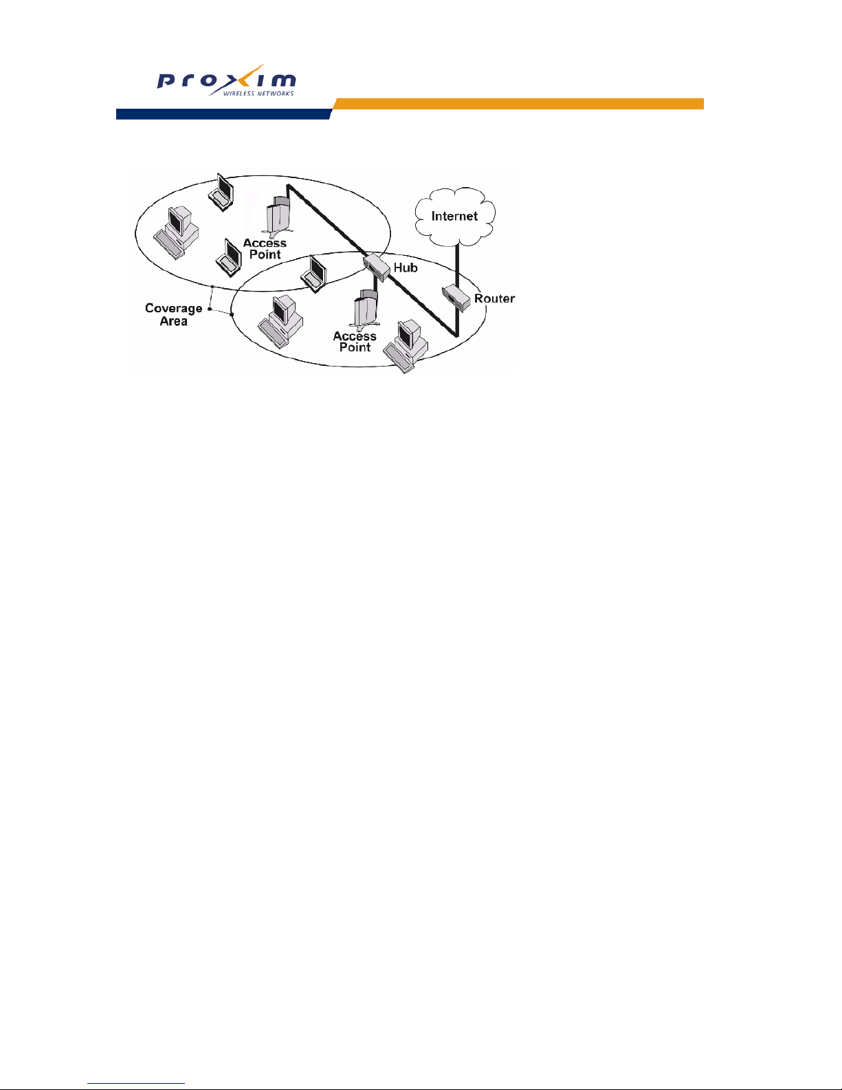
Figure 1-1 Typical wireless network access infrastructure
Once initialized, the network administrator can configure each unit according to the network’s requirements. The AP
functions as a wireless network access point to data networks. An AP network provides:
• Seamless client roaming
• Easy installation and operation
• Over-the-air encryption of data
• High speed network links
Guidelines for Roaming
• An AP can only communicate with client devices that support its wireless standard. For example, an 802.11a client
cannot communicate with an 802.11b AP and an 802.11b client cannot communicate with an 802.11a AP.
However, both 802.11b and 802.11g clients can communicate with an 802.11b/g AP.
• All Access Points must have the same Network Name to support client roaming.
• All workstations with an 802.11 client adapter installed must use either a Network Name of “any” or the same
Network Name as the Access Points that they will roam between. If an AP has Closed System enabled, a client
must have the same Network Name as the Access Point to communicate (see
Interfaces).
• All Access Points and clients must have the same security settings to communicate.
• The Access Points’ cells must overlap to ensure that there are no gaps in coverage and to ensure that the roaming
client will always have a connection available.
• The coverage area of an 802.11b or 802.11b/g AP is larger than the coverage area of an 802.11a AP. The 802.11b
and 802.11b/g APs operate in the 2.4 GHz frequency band; the 802.11a AP operates in the 5 GHz band. Products
that operate in the 2.4 GHz band offer greater range than products that operate in the 5 GHz band.
• An 802.11a or 802.11b/g AP operates at faster data rates than the 802.11b AP. 802.11a and 802.11g products
operate at speeds of up to 54 Mbits/sec; 802.11b products operate at speeds of up to 11 Mbits/sec.
• All Access Points in the same vicinity should use a unique, independent Channel. By default, the AP automatically
scans for available Channels during boot-up but you can also set the Channel manually (see Interfaces for details).
• Access Points that use the same Channel should be installed as far away from each other as possible to reduce
potential interference.
Page 14

14
Introduction
IEEE 802.11 Specifications
In 1997, the Institute of Electrical and Electronics Engineers (IEEE) adopted the 802.11 standard for wireless devices
operating in the 2.4 GHz frequency band. This standard includes provisions for three radio technologies: direct
sequence spread spectrum, frequency hopping spread spectrum, and infrared. Devices that comply with the 802.11
standard operate at a data rate of either 1 or 2 Megabits per second (Mbits/sec).
In 1999, the IEEE modified the 802.11 standard to support direct sequence devices that can operate at speeds of up to
11 Mbits/sec. The IEEE ratified this standard as 802.11b. 802.11b devices are backwards compatible with 2.4 GHz
802.11 direct sequence devices (that operate at 1 or 2 Mbits/sec). Available Frequency Channels vary by regulatory
domain and/or country. See
802.11b Channel Frequencies for details.
Also in 1999, the IEEE modified the 802.11 standard to support devices operating in the 5 GHz frequency band. This
standard is referred to as 802.11a. 802.11a devices are not compatible with 2.4 GHz 802.11 or 802.11b devices.
802.11a radios use a radio technology called Orthogonal Frequency Division Multiplexing (OFDM) to achieve data
rates of up to 54 Mbits/sec. Available Frequency Channels vary by regulatory domain and/or country. See
802.11a
Channel Frequencies for details.
In 2003, the IEEE introduced the 802.11g standard. 802.11g devices operate in the 2.4 GHz frequency band using
OFDM to achieve data rates of up to 54 Mbits/sec. In addition, 802.11g devices are backwards compatible with
802.11b devices. Available Frequency Channels vary by regulatory domain and/or country. See
802.11g Channel
Frequencies for details.
Management and Monitoring Capabilities
There are several management and monitoring interfaces available to the network administrator to configure and
manage an AP on the network:
•
HTTP/HTTPS Interface
• Command Line Interface
• SNMP Management
HTTP/HTTPS Interface
The HTTP Interface (Web browser Interface) provides easy access to configuration settings and network statistics
from any computer on the network. You can access the HTTP Interface over your LAN (switch, hub, etc.), over the
Internet, or with a “crossover” Ethernet cable connected directly to your computer’s Ethernet Port.
HTTPS provides an HTTP connection over a Secure Socket Layer. HTTPS is one of two available secure
management options on the AP; the other secure management option is SNMPv3. Enabling HTTPS allows the user to
access the AP in a secure fashion using Secure Socket Layer (SSL) over port 443. The AP supports SSLv3 with a
128-bit encryption certificate maintained by the AP for secure communications between the AP and the HTTP client.
All communications are encrypted using the server and the client-side certificate.
The AP comes pre-installed with all required SSL files: default certificate, private key and SSL Certificate Passphrase
installed.
Command Line Interface
The Command Line Interface (CLI) is a text-based configuration utility that supports a set of keyboard commands and
parameters to configure and manage an AP.
Users enter Command Statements, composed of CLI Commands and their associated parameters. Statements may
be issued from the keyboard for real time control, or from scripts that automate configuration.
For example, when downloading a file, administrators enter the download CLI Command along with IP Address, file
name, and file type parameters.
You access the CLI over a HyperTerminal serial connection or via Telnet. During initial configuration, you can use the
CLI over a serial port connection to configure an Access Point’s IP address. When accessing the CLI via Telnet, you
can communicate with the Access Point from over your LAN (switch, hub, etc.), from over the Internet, or with a
“crossover” Ethernet cable connected directly to your computer’s Ethernet Port.
See
Using the Command Line Interface (CLI) for more information on the CLI and for a list of CLI commands and
parameters.
Page 15

15
Introduction
SNMP Management
In addition to the HTTP and the CLI interfaces, you can also manage and configure an AP using the Simple Network
Management Protocol (SNMP). Note that this requires an SNMP manager program, like HP Openview or Castlerock’s
SNMPc.
The AP supports several Management Information Base (MIB) files that describe the parameters that can be viewed
and/or configured over SNMP:
– MIB-II (RFC 1213)
– Bridge MIB (RFC 1493)
– Ethernet-like MIB (RFC 1643)
– 802.11 MIB
– ORiNOCO Enterprise MIB
Proxim provides these MIB files on the CD included with each Access Point. You need to compile one or more of the
above MIBs into your SNMP program’s database before you can manage an Access Point using SNMP. Refer to the
documentation that came with your SNMP manager for instructions on how to compile MIBs.
The Enterprise MIB defines the read and read-write objects that can be viewed or configured using SNMP. These
objects correspond to most of the settings and statistics that are available with the other management interfaces. Refer
to the Enterprise MIB for more information; the MIB can be opened with any text editor, such as Microsoft Word,
Notepad, or WordPad.
SNMPv3 Secure Management
SNMPv3 is one of two available secure management options on the AP; the other secure management option is
HTTPS (HTTP connection over Secure Socket Layer). SNMPv3 is based on the existing SNMP framework, but
addresses security requirements for device and network management.
The security threats addressed by Secure Management are:
• Modification of information: An entity could alter an in-transit message generated by an authorized entity in such a
way as to effect unauthorized management operations, including the setting of object values. The essence of this
threat is that an unauthorized entity could change any management parameter, including those related to
configuration, operations, and accounting
• Masquerade: Management operations that are not authorized for some entity may be attempted by that entity by
assuming the identity of an authorized entity.
• Message stream modification: SNMP is designed to operate over a connectionless transport protocol. There is a
threat that SNMP messages could be reordered, delayed, or replayed (duplicated) to effect unauthorized
management operations. For example, a message to reboot a device could be copied and replayed later.
• Disclosure: An entity could observe exchanges between a manager and an agent and thereby learns the values of
managed objects and learn of notifiable events. For example, the observation of a set command that changes
passwords would enable an attacker to learn the new passwords.
To address the security threats listed above, SNMPv3 provides the following when secure management is enabled:
• Authentication: Provides data integrity and data origin authentication.
• Privacy (a.k.a Encryption): Protects against disclosure of message payload.
• Access Control: Controls and authorizes access to managed objects
The default SNMPv3 username is administrator, with SHA authentication, and DES privacy protocol.
NOTE
The remainder of this guide describes how to configure an AP using the HTTP Web interface or the CLI
interface. For information on how to manage devices using SNMP, refer to the documentation that came with
your SNMP program. Also, refer to the MIB files for information on the parameters available via SNMP.
Page 16

16
2
Getting Started
• Prerequisites
• Product Package
• System Requirements
• Hardware Installation
• Initialization
• Download the Latest Software
• Additional Hardware Features
Prerequisites
Before installing an AP, you need to gather certain network information. The following section identifies the information
you need.
NOTE
Passwords must be configured with at least 6 characters in length.
Network Name (SSID of the wireless cards) You must assign the Access Point a Primary Network Name before wireless users can
communicate with it. The clients also need the same Network Name. This is not the same
as the System Name, which applies only to the Access Point. The network administrator
typically provides the Network Name.
AP’s IP Address If you do not have a DHCP server on your network, then you need to assign the
Access Point an IP address that is valid on your network.
HTTP Password Each Access Point requires a read/write password to access the web interface. The default
password is “public”.
CLI Password Each Access Point requires a read/write password to access the CLI interface. The default
password is “public”.
SNMP Read Password Each Access Point requires a password to allow get requests from an SNMP manager.
The default password is “public”.
SNMP Read-Write Password Each Access Point requires a password to allow get and set requests from an SNMP
manager. The default password is “public”. This password must be at least 6 characters in
length.
SNMPv3 Authentication Password If Secure Management is enabled, each Access Point requires a password for sending
authenticated SNMPv3 messages. The default password is “public”.
The default SNMPv3 username is administrator, with SHA authentication, and DES
privacy protocol.
SNMPv3 Privacy Password If Secure Management is enabled, each Access Point requires a password when sending
encrypted SNMPv3 data. The default password is “public”.
Security Settings You need to determine what security features you will enable on the Access Point.
Authentication Method A primary authentication server may be configured; a backup authentication server is
optional. The network administrator typically provides this information.
Authentication Server Shared Secret This is a password shared between the Access Point and the RADIUS authentication
server (so both passwords must be the same), and is typically provided by the network
administrator.
Authentication Server Authentication Port This is a port number (default is 1812) and is typically provided by the network
administrator.
Client IP Address Pool Allocation Scheme The Access Point can automatically provide IP addresses to clients as they sign on. The
network administrator typically provides the IP Pool range.
DNS Server IP Address The network administrator typically provides this IP Address.
Page 17

17
Getting Started
Product Package
Each Single-radio AP comes with the following:
• One metal base for ceiling or desktop mounting (includes two screws)
• Mounting hardware
– Four 3.5 mm x 40 mm screws
– Four 6 mm x 35 mm plugs
• One power supply
• One Installation CD-ROM that contains the following:
– Software Installation Wizard
– ScanTool
– Solarwinds TFTP software
– HTML Help
– this user’s guide in PDF format
• One Access Point Quick Start Guide
If any of these items are missing or damaged, please contact your reseller or Technical Support (see
Technical
Support for contact information).
MiniPCI Upgrade Kits
Single-radio APs can be fitted with different radio types. MiniPCI upgrade kits are available for 802.11a/b/g and
802.11b/g wireless cards. Each kit is composed of a single miniPCI board with an integral antenna attached. The type
of radio is indicated on the label on the antenna and instructions on how to open your AP to replace the radio are
provided with the kit.
System Requirements
To begin using an AP, you must have the following minimum requirements:
• A 10Base-T Ethernet or 100Base-TX Fast Ethernet switch or hub
• At least one of the following IEEE 802.11-compliant devices:
– An 802.11a client device if you have an 802.11a AP
– An 802.11b or 802.11b/g client device if you have an 802.11b AP
– An 802.11b/g client device if you have an 802.11b/g AP
– An 802.11a/g client device if you have an 802.11a/g AP
• A computer that is connected to the same IP network as the AP and has one of the following Web browsers
installed:
– Microsoft Internet Explorer 6 with Service Pack 1 or later and patch Q323308
– Netscape 6.1 or later
(The computer is required to configure the AP using the HTTP interface.)
Page 18
18
Getting Started
Hardware Installation
Follow these steps to install a Single-radio AP:
1. Unpack the Access Point and accessories from the shipping box.
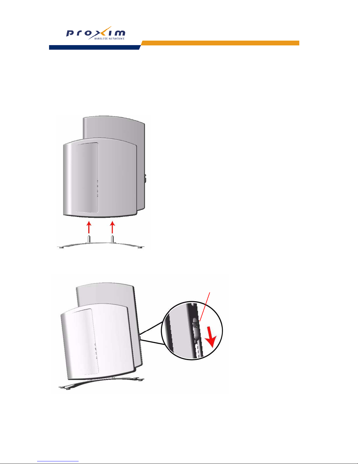
2. If you intend to install the unit free-standing or if you intend to mount it to the ceiling, use a Phillips screwdriver to
attach the metal base to the underside of the unit. The metal base and screws are provided. See
Mounting Options
for additional information.
Figure 2-1 Attach the Metal Base
3. Press down on the cable-cover lock located in the front-center of the unit to release the cable cover.
Figure 2-2 Unlock the Cable Cover
4. Remove the cable cover from the unit.
cable-cover lock
Page 19
19
Getting Started
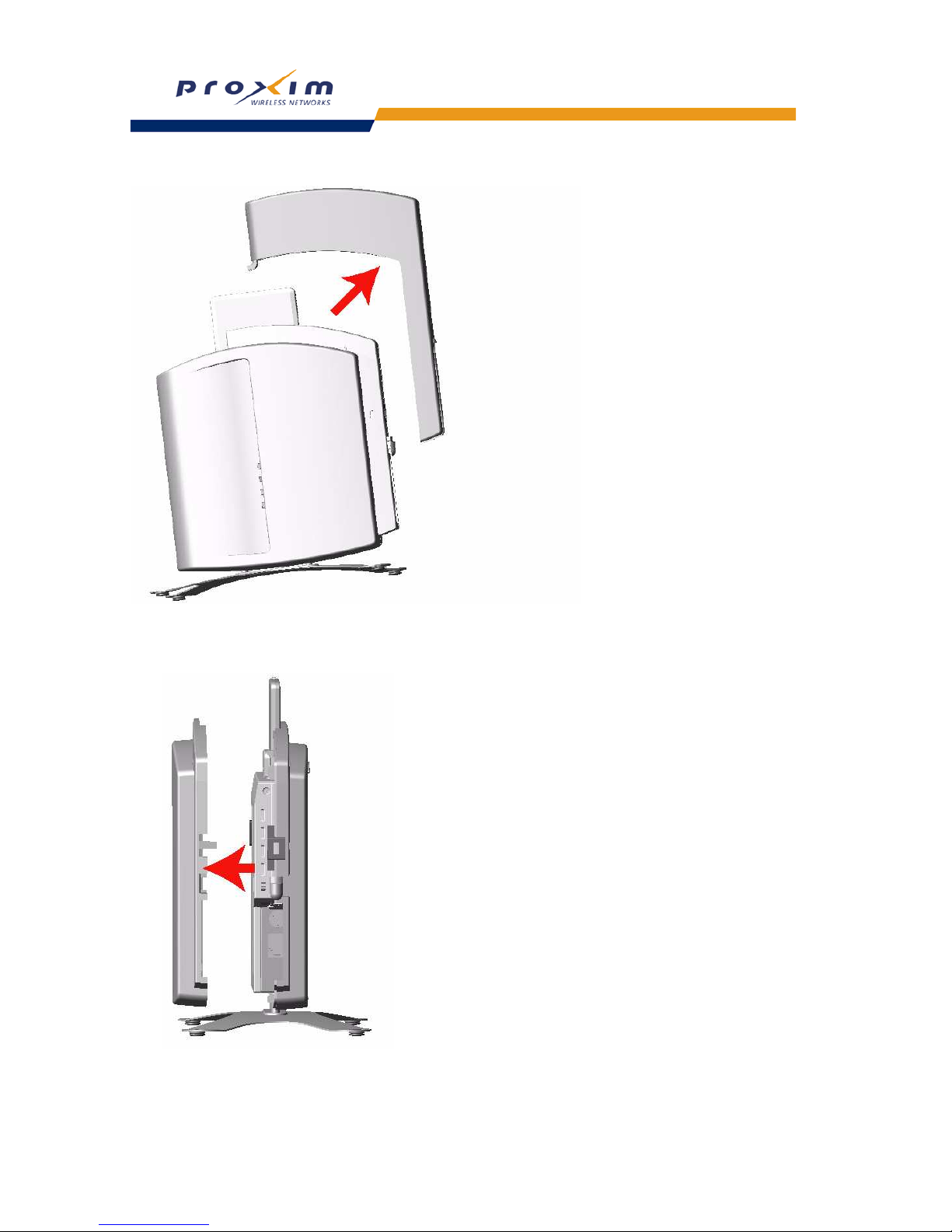
Figure 2-3 Remove Cable Cover
5. Remove the front cover (the side with the LED indicators) from the unit.
Figure 2-4 Remove the Front Cover
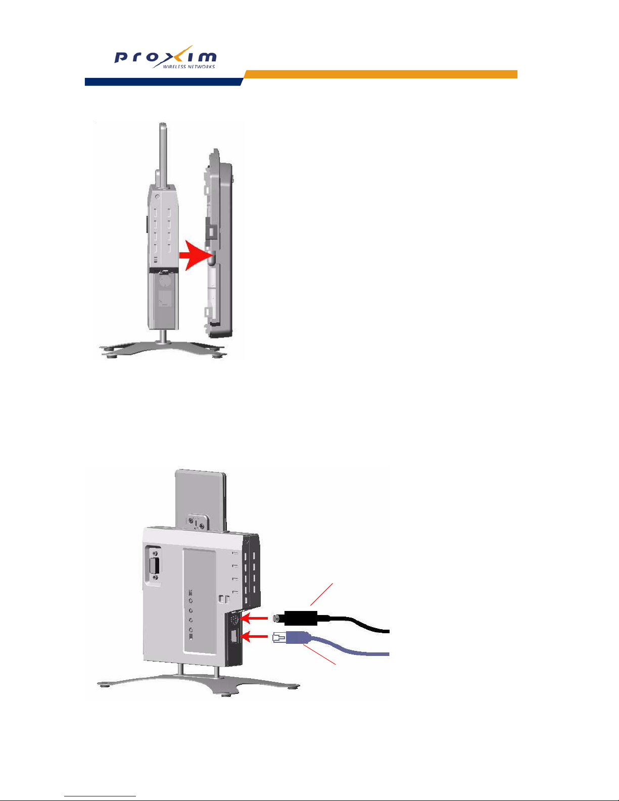
6. Remove the back cover from the unit.
Page 20
20
Getting Started
Figure 2-5 Remove the Back Cover
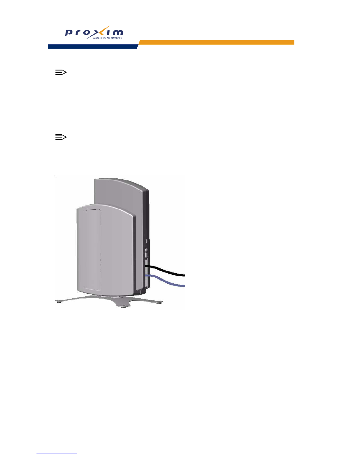
7. Connect one end of an Ethernet cable to the Access Point’s Ethernet port. The other end of the cable should not
be connected to another device until after the installation is complete.
• Use a straight-through Ethernet cable if you intend to connect the Access Point to a hub, switch, patch panel,
or Active Ethernet power injector.
• Use a cross-over Ethernet cable if you intend to connect the Access Point to a single computer.
8. If you are not using Active Ethernet (or you want to connect the Access Point to Active Ethernet and AC power
simultaneously), attach the AC power cable to the Access Point’s power port.
Figure 2-6 Attach Ethernet Cable and Power Cable
Ethernet Cable
Power Cable
Page 21
21
Getting Started
NOTE
Once attached, the power cable locks into place. To disconnect the power cable, slide back the black plastic
fitting and gently pull the cable from the connector.
9. Connect the free end of the Ethernet cable to a hub, switch, patch panel, Active Ethernet power injector, or an
Ethernet port on a computer.
10. If using AC power, connect the power cord to a power source (such as a wall outlet) to turn on the unit.
11. Configure and test the unit. See Initialization for details.
12. Download the latest software to the unit, if necessary. See Download the Latest Software for details.
13. Place the unit in the final installation location. See
Mounting Options for mounting options and instructions.
NOTE
Proxim recommends that you perform a Site Survey prior to determine the installation location for your AP
units. For information about how to conduct a Site Survey, contact your local reseller.
14. Replace the back cover, front cover, and cable cover. Be careful to avoid trapping the power and Ethernet cables
when replacing the cable cover.
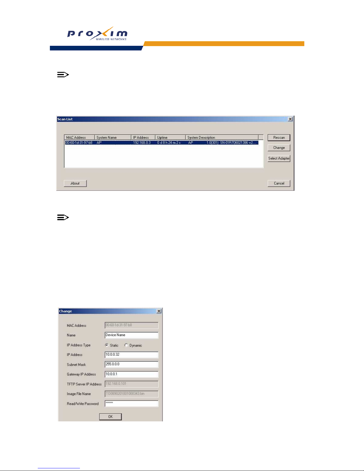
Figure 2-7 Assembled Unit
15. If desired, you can attach a Kensington lock to secure the cable cover into place. This will protect the unit from
unauthorized tampering. See Kensington Security Slot for details.
16.
Page 22

22
Getting Started
Initialization
Proxim provides two tools to simplify the initialization and configuration of an AP:
• ScanTool
• Setup Wizard
ScanTool is included on the Installation CD; the Setup Wizard launches automatically the first time you access the
HTTP interface.
NOTE
These initialization instructions describe how to configure an AP over an Ethernet connection using ScanTool
and the HTTP interface. If you want to configure the unit over the serial port, see Setting IP Address using
Serial Port
for information on how to access the CLI over a serial connection and Using the Command Line
Interface (CLI) for a list of supported commands.
ScanTool
ScanTool is a software utility that is included on the installation CD-ROM. ScanTool allows you to find the IP address of
an Access Point by referencing the MAC address in a Scan List, or to assign an IP address if one has not been
assigned.
The tool automatically detects the Access Points installed on your network, regardless of IP address, and lets you
configure each unit’s IP settings. In addition, you can use ScanTool to download new software to an AP that does not
have a valid software image installed (see
Client Connection Problems).
To access the HTTP interface and configure the AP, the AP must be assigned an IP address that is valid on its
Ethernet network. By default, the AP is configured to obtain an IP address automatically from a network Dynamic Host
Configuration Protocol (DHCP) server during boot-up. If your network contains a DHCP server, you can run ScanTool
to find out what IP address the AP has been assigned. If your network does not contain a DHCP server, the
Access Point’s IP address defaults to 169.254.128.132. In this case, you can use ScanTool to assign the AP a static IP
address that is valid on your network.
ScanTool Instructions
Follow these steps to install ScanTool, initialize the Access Point, and perform initial configuration:
1. Locate the unit’s Ethernet MAC address and write it down for future reference. The MAC address is printed on the
product label. Each unit has a unique MAC address, which is assigned at the factory.
2. Confirm that the AP is connected to the same LAN subnet as the computer that you will use to configure the AP.
3. Power up, reboot, or reset the AP.
– Result: The unit requests an IP Address from the network DHCP server.
4. Insert the Installation CD into the CD-ROM drive of the computer that you will use to configure the AP.
– Result: The installation program will launch automatically.
5. Follow the on-screen instructions to install the Access Point software and documentation.
NOTE
The ORiNOCO Installation program supports the following operating systems:
• Windows 98SE
• Windows 2000
• Windows NT
• Windows ME
• Windows XP
6. After the software has been installed, double-click the ScanTool icon on the Windows desktop to launch the
program (if the program is not already running).
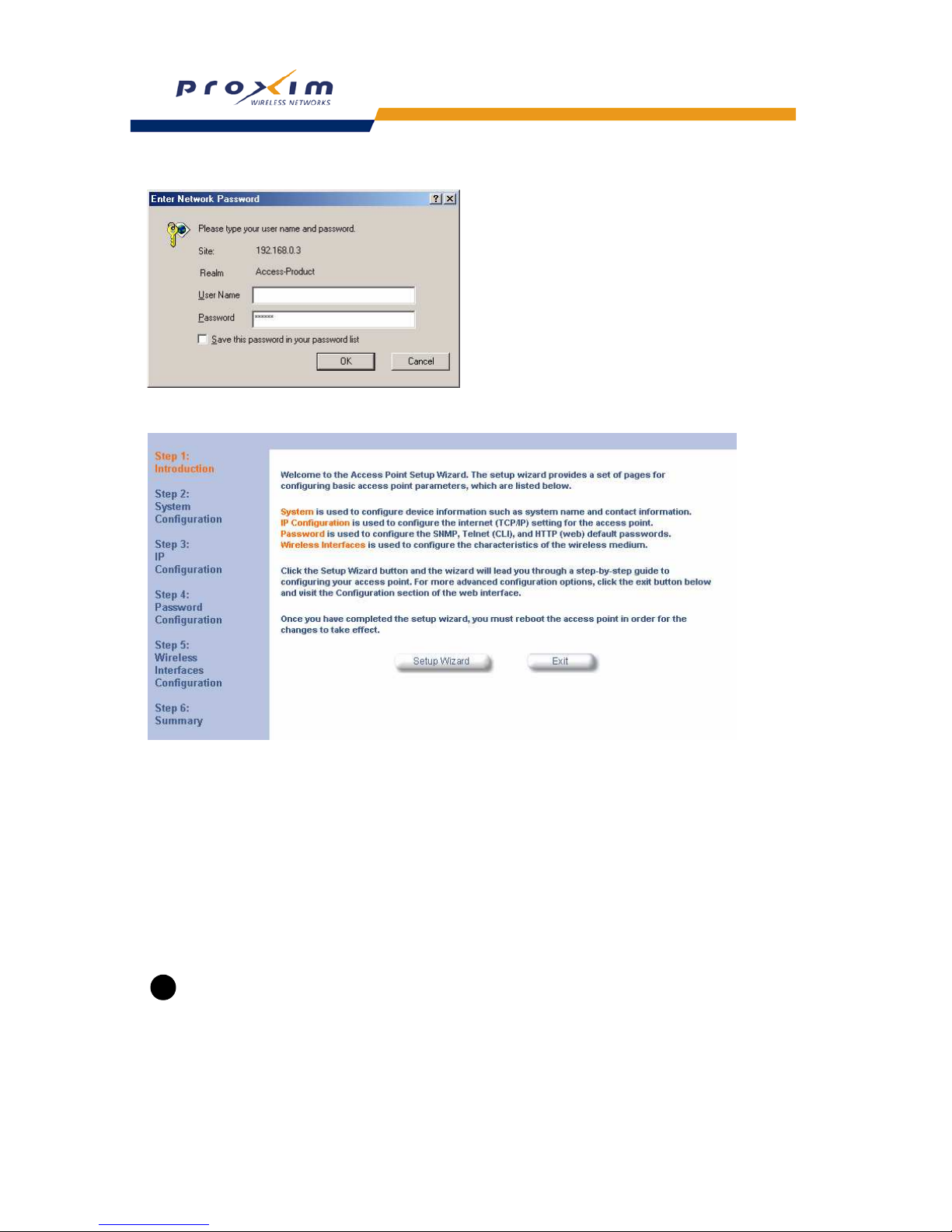
– Result: ScanTool scans the subnet and displays all detected Access Points. The ScanTool’s Scan List screen
appears, as shown in the following example.
Page 23
23
Getting Started
NOTE
If your computer has more than one network adapter installed, you will be prompted to select the adapter that
you want ScanTool to use before the Scan List appears. If prompted, select an adapter and click OK. You
can change your adapter setting at any time by clicking the Select Adapter button on the Scan List screen.
Note that the ScanTool Network Adapter Selection screen will not appear if your computer only has one
network adapter installed.
Figure 2-8 Scan List
7. Locate the MAC address of the AP you want to initialize within the Scan List.
NOTE
If your Access Point does not show up in the Scan List, click the Rescan button to update the display. If the
unit still does not appear in the list, see Troubleshooting the AP-2000 for suggestions. Note that after
rebooting an Access Point, it may take up to five minutes for the unit to appear in the Scan List.
8. Do one of the following:
• If the AP has been assigned an IP address by a DHCP server on the network, write down the IP address and
click Cancel to close ScanTool. Proceed to Setup Wizard for information on how to access the HTTP interface
using this IP address.
• If the AP has not been assigned an IP address (in other words, the unit is using its default IP address,
169.254.128.132), follow these steps to assign it a static IP address that is valid on your network:
1. Highlight the entry for the AP you want to configure.
2. Click the Change button.
— Result: the Change screen appears.
Page 24

24
Getting Started
Figure 2-9 Scan Tool Change Screen
3. Set IP Address Type to Static.
4. Enter a static IP Address for the AP in the field provided. You must assign the unit a unique address that
is valid on your IP subnet. Contact your network administrator if you need assistance selecting an IP
address for the unit.
5. Enter your network’s Subnet Mask in the field provided.
6. Enter your network’s Gateway IP Address in the field provided.
7. Enter the SNMP Read/Write password in the Read/Write Password field (for new units, the default
SNMP Read/Write password is “public”).
NOTE
The TFTP Server IP Address and Image File Name fields are only available if ScanTool detects that the AP
does not have a valid software image installed. See Client Connection Problems.
8. Click OK to save your changes.
— Result: The Access Point will reboot automatically and any changes you made will take effect.
9. When prompted, click OK a second time to return to the Scan List screen.
10. Click Cancel to close the ScanTool.
11. Proceed to
Setup Wizard for information on how to access the HTTP interface.
Setup Wizard
The first time you connect to an AP’s HTTP interface, the Setup Wizard launches automatically. The Setup Wizard
provides step-by-step instructions for how to configure the Access Point’s basic operating parameter, such as Network
Name, IP parameters, system parameters, and management passwords.
Setup Wizard Instructions
Follow these steps to access the Access Point’s HTTP interface and launch the Setup Wizard:
1. Open a Web browser on a network computer.
– The HTTP interface supports the following Web browser:
• Microsoft Internet Explorer 6 with Service Pack 1 or later
• Netscape 6.1 or later
2. If necessary, disable the browser’s Internet proxy settings. For Internet Explorer users, follow these steps:
– Select Tools > Internet Options.
– Click the Connections tab.
– Click LAN Settings.
– If necessary, remove the check mark from the Use a proxy server box.
– Click OK twice to save your changes and return to Internet Explorer.
3. Enter the Access Point’s IP address in the browser ’s Address field and press Enter.
– This is either the dynamic IP address assigned by a network DHCP server or the static IP address you
manually configured. See
ScanTool for information on how to determine the unit’s IP address and manually
configure a new IP address, if necessary.
– Result: The Enter Network Password screen appears.
4. Enter the HTTP password in the Password field. Leave the User Name field blank. For new units, the default
HTTP password is “public”.
– Result: The Setup Wizard will launch automatically.
Page 25
25
Getting Started
Figure 2-10 Enter Network Password
Figure 2-11 Setup Wizard
5. Click Setup Wizard to begin. If you want to configure the AP without using the Setup Wizard, click Exit and see
Performing Advanced Configuration.
The Setup Wizard supports the following navigation options:
• Save & Next Button: Each Setup Wizard screen has a Save & Next button. Click this button to submit any
changes you made to the unit’s parameters and continue to the next page. The instructions below describe
how to navigate the Setup Wizard using the Save & Next buttons.
• Navigation Panel: The Setup Wizard provides a navigation panel on the left-hand side of the screen. Click
the link that corresponds to the parameters you want to configure to be taken to that particular configuration
screen. Note that clicking a link in the navigation panel will not submit any changes you made to the unit’s
configuration on the current page.
• Exit: The navigation panel also includes an Exit option. Click this link to close the Setup Wizard at any time.
CAUTION
!
If you exit from the Setup Wizard, any changes you submitted (by clicking the Save & Next button) up to that
point will be saved to the unit but will not take effect until it is rebooted.
6. Configure the System Configuration settings and click Save & Next. See System for more information.
7. Configure the Access Point’s Basic IP address settings, if necessary, and click Save & Next. See Basic IP
Parameters for more information.
Page 26

26
Getting Started
8. Assign the AP new passwords to prevent unauthorized access and click Save & Next. Each management
interface has its own password:
— SNMP Read Password
— SNMP Read-Write Password
— SNMPv3 Authentication Password
— SNMPv3 Privacy Password
— CLI Password
— HTTP (Web) Password
By default, each of these passwords is set to “public”. See
Passwords for more information.
9. Configure the basic wireless interface settings and click Save & Next.
• The following options are available for an 802.11a AP:
— Primary Network Name (SSID): Enter a Network Name (between 1 and 32 characters long) for the
wireless network. You must configure each wireless client to use this name as well.
— Additional Network Names (SSIDs): The AP supports up to 16 SSIDs and VLANs per wireless interface
(radio). Refer to the Advanced Configuration chapter for information on the detailed rules on configuring
multiple SSIDs, VLANs, and security modes.
— Auto Channel Select: By default, the AP scans the area for other Access Points and selects the best
available communication channel, either a free channel (if available) or the channel with the least amount
of interference. Remove the check mark to disable this option. Note that you cannot disable Auto Channel
Select for 802.11a products in Europe (see
Dynamic Frequency Selection (DFS) for details).
— Frequency Channel: When Auto Channel Select is enabled, this field is read-only and displays the
Access Point’s current operating channel. When Auto Channel Select is disabled, you can specify the
Access Point’s channel. If you decide to manually set the unit’s channel, ensure that nearby devices do
not use the same frequency. Available Channels vary based on regulatory domain. See 802.11a Channel
Frequencies
. Note that you cannot manually set the channel for 802.11a products in Europe (see
Dynamic Frequency Selection (DFS) for details).
— Transmit Rate: Use the drop-down menu to select a specific transmit rate for the AP. Choose between 6,
9, 12, 18, 24, 36, 48, 54 Mbits/s, and Auto Fallback. The Auto Fallback feature allows the AP to select the
best transmit rate based on the cell size.
• The following options are available for an 802.11b AP:
— Primary Network Name (SSID): Enter a Network Name (between 1 and 32 characters long) for the
wireless network. You must configure each wireless client to use this name as well.
— Additional Network Names (SSIDs): The AP supports up to 16 SSIDs and VLANs per wireless interface
(radio). Refer to the Advanced Configuration chapter for information on the detailed rules on configuring
multiple SSIDs, VLANs, and security modes.
— Auto Channel Select: By default, the AP scans the area for other Access Points and selects the best
available communication channel, either a free channel (if available) or the channel with the least amount
of interference. Remove the check mark to disable this option. If you are setting up a Wireless Distribution
System (WDS), it must be disabled. See
Wireless Distribution System (WDS) for more information.
— Frequency Channel: When Auto Channel Select is enabled, this field is read-only and displays the
Access Point’s current operating channel. When Auto Channel Select is disabled, you can specify the
Access Point’s operating channel. If you decide to manually set the unit’s channel, ensure that nearby
devices do not use the same frequency (unless you are setting up a WDS). Available Channels vary
based on regulatory domain. See
802.11b Channel Frequencies.
— Distance Between APs: Set to Large, Medium, Small, Microcell, or Minicell depending on the site
survey for your system. The distance value is related to the Multicast Rate (described next). In general, a
larger distance between APs means that your clients operate a slower data rates (on average). This
feature is available only if you are using an Orinoco Classic Gold card. See
Distance Between APs for
more information.
— Multicast Rate: Sets the rate at which Multicast messages are sent. This value is related to the Distance
Between APs parameter (described previously). The table below displays the possible Multicast Rates
based on the Distance between APs. This feature is available only if you are using an Orinoco Classic
Gold card. See
Multicast Rate for more information.
Page 27

27
Getting Started
• The following options are available for an 802.11b/g AP:
— Operational Mode: An 802.11b/g wireless interface can be configured to operate in the following modes:
— 802.11b mode only
— 802.11g mode only
— 802.11g-wifi mode
— 802.11b/g mode (default)
— Primary Network Name (SSID): Enter a Network Name (between 1 and 32 characters long) for the
wireless network. You must configure each wireless client to use this name as well.
— Additional Network Names (SSIDs): The AP supports up to 16 SSIDs and VLANs per wireless interface
(radio). Refer to the Advanced Configuration chapter for information on the detailed rules on configuring
multiple SSIDs, VLANs, and security modes.
— Auto Channel Select: By default, the AP scans the area for other Access Points and selects the best
available communication channel, either a free channel (if available) or the channel with the least amount
of interference. Remove the check mark to disable this option.
— Frequency Channel: When Auto Channel Select is enabled, this field is read-only and displays the
Access Point’s current operating channel. When Auto Channel Select is disabled, you can specify the
Access Point’s channel. If you decide to manually set the unit’s channel, ensure that nearby devices do
not use the same frequency. Available Channels vary based on regulatory domain. See
802.11g Channel
Frequencies.
— Transmit Rate: Select a specific transmit rate for the AP. The values available depend on the
Operational Mode. Auto Fallback is the default setting; it allows the AP to select the best transmit rate
based on the cell size.
— For 802.11b only -- Auto Fallback, 1, 2, 5.5, 11 Mbits/sec
— For 802.11g only -- Auto Fallback, 6, 9, 12, 18, 24, 36, 48, 54 Mbits/sec
— For 802.11b/g and 802.11g-wifi-- Auto Fallback, 1, 2, 5.5, 6, 9, 11, 12, 18, 24, 36, 48, 54 Mbits/sec
NOTE
Additional advanced settings are available in the Wireless Interface Configuration screen. See Wireless A
(802.11a), Wireless (802.11b), or Wireless (802.11b/g) for details. See SSID/VLAN/Security for more
information on security features.
10. Review the configuration summary. If you want to make any additional changes, use the navigation panel on the
left-hand side of the screen to return to an earlier screen. After making a change, click Save & Next to save the
change and proceed to the next screen.
11. When finished, click Reboot on the Summary screen to restart the AP and apply your changes.
Download the Latest Software
Proxim periodically releases updated software for the AP on its Web site at http://www.proxim.com. Proxim
recommends that you check the Web site for the latest updates after you have installed and initialized the unit.
Three types of files can be downloaded to the AP from a TFTP server:
— image (AP software image or kernel)
— config (configuration file)
— UpgradeBSPBL (BSP/Bootloader firmware file)
Distance between APs Multicast Rate
Large 1 and 2 Mbits/sec
Medium 1, 2, and 5.5 Mbits/sec
Small 1, 2, 5.5 and 11 Mbits/sec
Minicell 1, 2, 5.5 and 11 Mbits/sec
Microcell 1, 2, 5.5 and 11 Mbits/sec
Page 28

28
Getting Started
Setup your TFTP Server
A Trivial File Transfer Protocol (TFTP) server allows you to transfer files across a network. You can upload files from
the AP for backup or copying, and you can download the files for configuration and AP Image upgrades. The
Solarwinds TFTP server software is located on the ORiNOCO AP Installation CD-ROM. You can also download the
latest TFTP software from Solarwind’s Web site at
http://www.solarwinds.net.
NOTE
If a TFTP server is not available in the network, you can perform similar file transfer operations using the
HTTP interface.
After the TFTP server is installed:
• Check to see that TFTP is configured to point to the directory containing the AP Image.
• Make sure you have the proper TFTP server IP address, the proper AP Image file name, and that the TFTP server
is operational.
• Make sure the TFTP server is configured to both Transmit and Receive files, with no automatic shutdown
or time-out.
Download Updates from your TFTP Server using the Web Interface
1. Download the latest software from http://www.proxim.com.
2. Copy the latest software updates to your TFTP server.
3. In the Web Interface, click the Commands button and select the Update AP tab.
4. Enter the IP address of your TFTP server in the field provided.
5. Enter the File Name (including the file extension). Enter the full directory path and file name. If the file is located in
the default TFTP directory, you need enter only the file name.
6. Select the File Type from the drop-down menu (use Img for software updates).
7. Select Update AP & Reboot from the File Operation drop-down menu.
8. Click Update.
9. The Access Point will reboot automatically when the download is complete.
Page 29

29
Getting Started
Download Updates from your TFTP Server using the CLI Interface
1. Download the latest software from http://www.proxim.com.
2. Copy the latest software updates to your TFTP server.
3. Open the CLI interface via Telnet or a serial connection.
4. Enter the CLI password when prompted.
5. Enter the command: download <tftpaddr> <filename> img
– Result: The download will begin. Be patient while the image is downloaded to the Access Point.
6. When the download is complete, type reboot 0 and press Enter.
NOTE
See Using the Command Line Interface (CLI) for more information.
Additional Hardware Features
• Mounting Options
• Installing the AP in a Plenum
• Kensington Security Slot
• Active Ethernet
• LED Indicators
Mounting Options
There are three mounting options for the AP, described below.
Desktop Mount
This is the standard installation for the AP. See Hardware Installation for instructions.
Wall Mount
Follow these steps to mount the AP on a wall:
1. Identify the location where you intend to mount the unit.
NOTE
For best results, mount the unit vertically. In other words, the antenna should be pointing up or down but not
sideways.
2. Unplug the Access Point’s power supply, if necessary.
3. Use a Phillips screwdriver to remove the metal base from the underside of the AP, if necessary.
4. Press down on the cable cover lock to release the cable cover. See Unlock the Cable Cover for an illustration.
5. Remove the cable cover from the unit. See
Remove Cable Cover for an illustration.
6. Remove the front cover from the unit. See Remove the Front Cover for an illustration.
7. Remove the back cover from the unit. See Remove the Back Cover for an illustration.
8. Place the back cover on the mounting location and mark the center of the three mounting holes.
9. Remove the cover from the wall and drill a hole at each of the locations you marked above. Each hole should be
wide enough to hold a mounting plug (which is 6 mm x 35 mm).
10. Insert a plug into each hole. The AP comes with four 6 mm x 35 mm plugs; you only need to use three of these
when wall mounting the unit.
11. Insert a screw into each of the mounting holes molded into the back cover. The AP comes with four 3.5 mm x 40
mm pan-head screws; you only need to use three of these when wall mounting the unit.
12. Insert the screws into the wall plugs. Use a screwdriver to tighten the screws and attach the back cover to the wall.
In the following example, the back cover is mounted upside down (the two holes are at the bottom).
Page 30
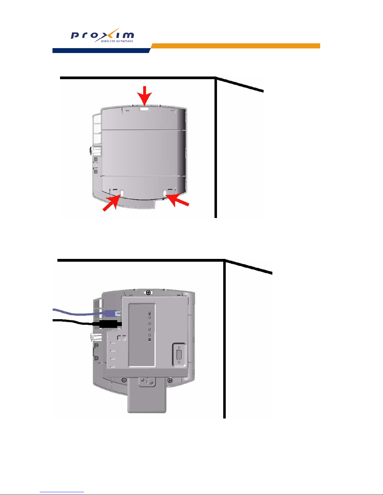
30
Getting Started
Figure 2-12 Attach the Back Cover to the Wall
13. Attach Ethernet and power cables to the AP unit, if necessary.
14. Snap the unit into the back cover. In the following example, the unit is mounted upside down and its antenna is
facing down.
Figure 2-13 AP Mounted on a Wall
Page 31
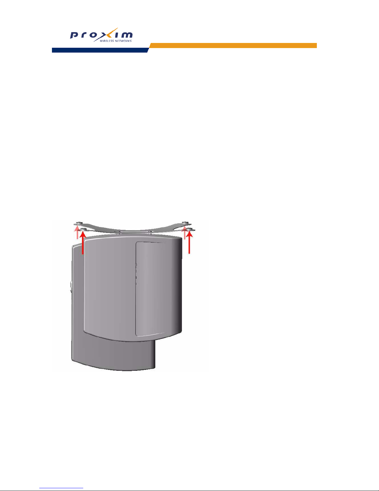
31
Getting Started
15. Replace the front cover.
16. Replace the cable cover.
17. Turn on the AP.
Ceiling Mount
Follow these steps to mount the AP to a ceiling:
1. Unplug the Access Point’s power supply, if necessary.
2. Use a Phillips screwdriver to attach the metal base to the underside of the AP, if necessary. See Attach the Metal
Base for an illustration.
3. Feed a mounting screw through each of the four rubber feet. The AP comes with four 3.5 mm x 40 mm pan-head
screws.
4. Remove the screws from the rubber feet.
5. Turn the AP upside down position the base against the ceiling where you want to mount the unit.
6. Mark the center of the four mounting holes in the rubber feet.
7. Set the AP aside and drill a hole at each of the locations you marked above. Each hole should be wide enough to
hold a mounting plug (which is 6 mm x 35 mm).
8. Insert a plug into each hole. The AP comes with four 6 mm x 35 mm plugs.
9. Insert the screws into the holes you made previously in the rubber feet.
10. Insert the screws into the wall plugs. Use a screwdriver to tighten the screws and attach the Access Point’s metal
base to the ceiling.
Figure 2-14 Mounting the AP to the Ceiling
Installing the AP in a Plenum
In an office building, plenum is the space between the structural ceiling and the tile ceiling that is provided to help air
circulate. Many companies also use the plenum to house communication equipment and cables. However, these
products and cables must comply with certain safety requirements, such as Underwriter Labs (UL) Standard 2043:
“Standard for Fire Test for Heat and Visible Smoke Release for Discrete Products and Their Accessories Installed in
Air-Handling Spaces”.
Page 32
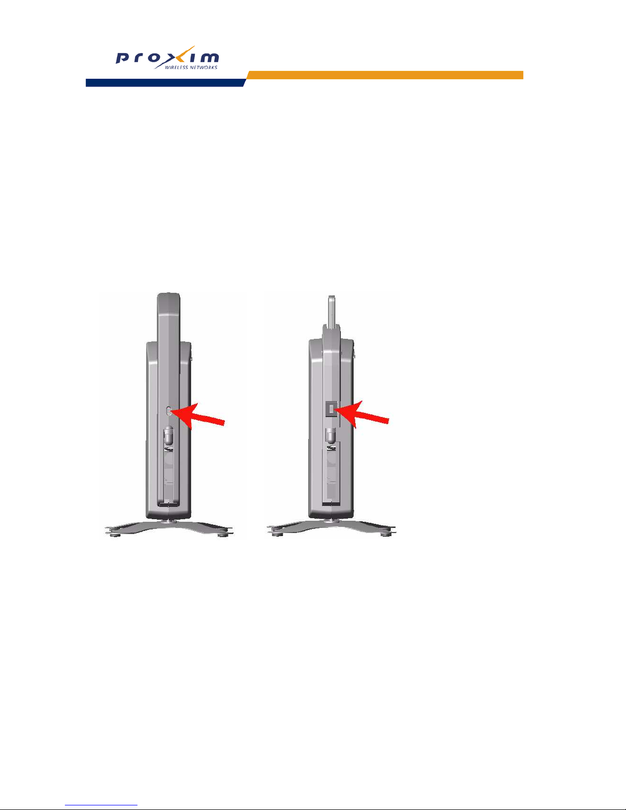
32
Getting Started
The AP has been certified under UL Standard 2043 and can be installed in the plenum only when the following
conditions apply:
• The unit uses Active Ethernet (AE) to receive power over a plenum-rated Category 5 Ethernet cable (the
power cable must not be connected to the unit).
• The unit’s plastic covers have been removed (this includes the cable cover, the front cover, and the back
cover).
Kensington Security Slot
The AP enclosure includes a Kensington Security Slot for use with a Kensington locking mechanism. When properly
installed, a Kensington lock can prevent unauthorized personnel from stealing the AP. In addition, the Kensington locks
secures the cable cover in place, which prevents tampering with the Ethernet and power cables.
The Kensington Security Slot is shown in the illustrations below (the figure on the left shows the slot with the cable
cover attached; the figure on the right shows the slot with the cable cover removed). See
http://www.kensington.com
for information on Kensington security solutions.
Figure 2-15 Kensington Security Slot
Page 33

33
Getting Started
Active Ethernet
An Active Ethernet-enabled AP is equipped with an 802.3af-compliant Active Ethernet module. Active Ethernet (AE)
delivers both data and power to the access point over a single Ethernet cable. If you choose to use Active Ethernet,
there is no difference in operation; the only difference is in the power source.
– The Active Ethernet (AE) integrated module receives ~48 VDC over a standard Category 5 Ethernet cable.
– To use Active Ethernet, you must have an AE hub (also known as a power injector) connected to the network.
– The cable length between the AE hub and the Access Point should not exceed 100 meters (approximately
325 feet).
– The AE hub is not a repeater and does not amplify the Ethernet data signal.
– If connected to an AE hub and an AC power simultaneously, the Access Point draws power from Active
Ethernet.
– Maximum power supplied to an Access Point is 11 Watts; the unit typically draws approximately 10 Watts.
Also see
Hardware Specifications.
NOTE
The AP’s 802.3af-compliant Active Ethernet module is backwards compatible with all ORiNOCO Active
Ethernet hubs that do not support the IEEE 802.3af standard.
LED Indicators
The AP has four LED indicators. The LEDs are identified in LED Indicators Illustrated and exhibit the following
behavior:
Power Ethernet Link Ethernet Activity Wireless Activity Indication
Solid Green Green when link
exists
Green flash
with data activity
Green flash
with data activity
Normal Operation
Solid Amber Solid Amber Solid Amber Solid Amber Rebooting/Power on Self Test (POST)
Solid Green Solid Amber Solid Amber Solid Amber Reset to Factory Defaults command issued
Solid Red Off Off Off SDRAM Test Failure
Blinking Red Blinking Red or Off Blinking Red Off Hardware Timer Test Failure
Blinking Red Off Off Blinking Red Flash Test Failure
Solid Red Blinking Red or Off Solid Red Off Ethernet Test Failure
Solid Red Off Off Solid Red Wireless Test Failure
Blinking Amber Blinking Amber or Off Blinking Amber or Off Off Missing or bad AP image
Solid Amber Solid Amber Solid Amber Solid Amber Missing or bad bootloader image (all LEDs
remain solid amber)
n/a n/a n/a Red Wireless radio is not working properly
n/a n/a Amber Amber Indicated interface in administrative down state
Page 34
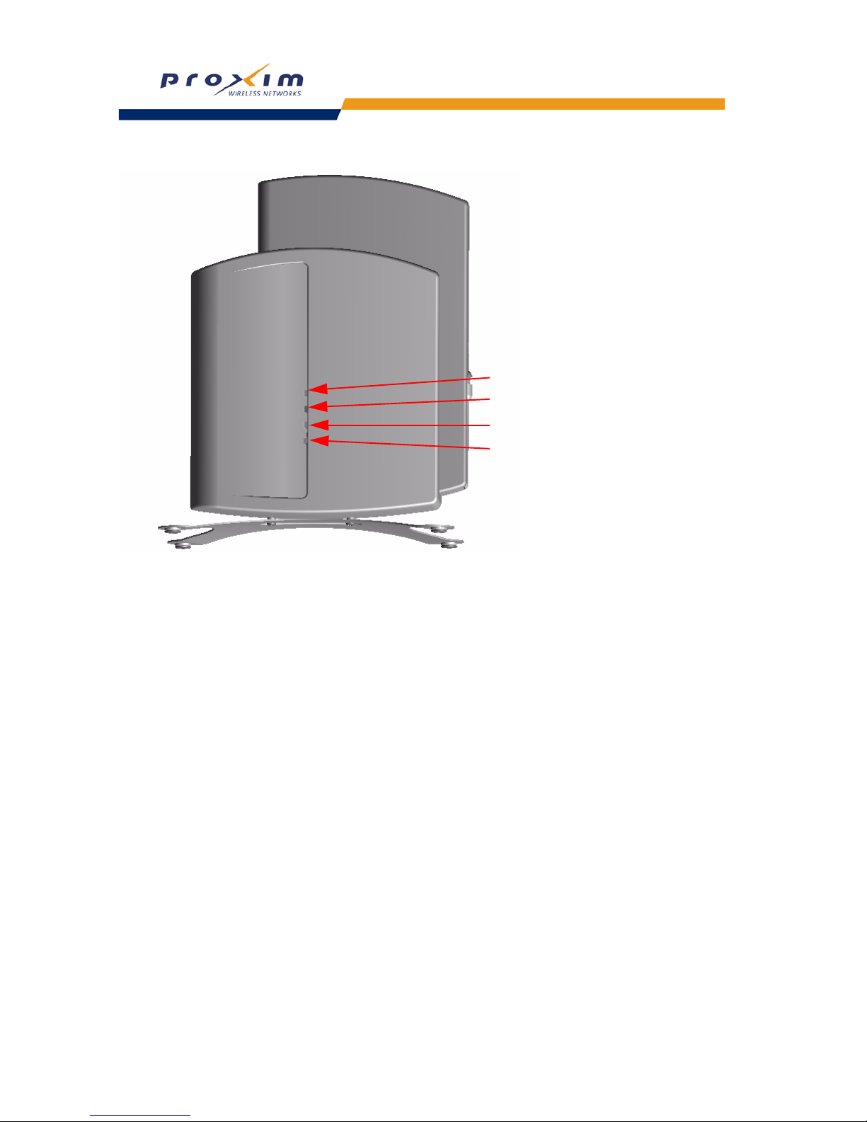
34
Getting Started
Figure 2-16 LED Indicators Illustrated
Power LED
Wireless Activity LED
Ethernet Activity LED
Ethernet Link LED
Page 35

35
Getting Started
Related Topics
The Setup Wizard helps you configure the basic AP settings required to get the unit up and running. The AP supports
many other configuration and management options. The remainder of this user guide describes these options in detail.
– See Performing Advanced Configuration for information on configuration options that are available within the
Access Point’s HTTP interface.
– See Monitoring the AP-2000 for information on the statistics displayed within the Access Point’s HTTP interface.
– See Performing Commands for information on the commands supported by the Access Point’s HTTP interface.
– See Troubleshooting the AP-2000 for troubleshooting suggestions.
– See
Using the Command Line Interface (CLI) for information on the CLI interface and for a list of CLI commands.
Page 36
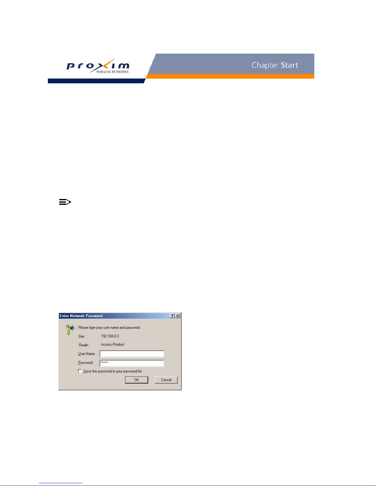
34
3
Viewing Status Information
• Logging into the HTTP Interface
• System Status
Logging into the HTTP Interface
Once the AP has a valid IP Address and an Ethernet connection, you may use your web browser to monitor the
system status.
Follow these steps to monitor an AP’s operating statistics using the HTTP interface:
1. Open a Web browser on a network computer.
NOTE
The HTTP interface supports the following Web browser:
• Microsoft Internet Explorer 6 with Service Pack 1 or later
• Netscape 6.1 or later
2. If necessary, disable the Internet proxy settings. For Internet Explorer users, follow these steps:
– Select Tools > Internet Options....
– Click the Connections tab.
– Click LAN Settings....
– If necessary, remove the check mark from the Use a proxy server box.
– Click OK twice to save your changes and return to Internet Explorer.
3. Enter the Access Point’s IP address in the browser ’s Address field and press Enter.
– Result: The Enter Network Password screen appears.
4. Enter the HTTP password in the Password field and click OK. Leave the User Name field blank. (By default, the
HTTP password is “public”).
– Result: The System Status screen appears.
Figure 3-1 Enter Network Password Screen
Page 37
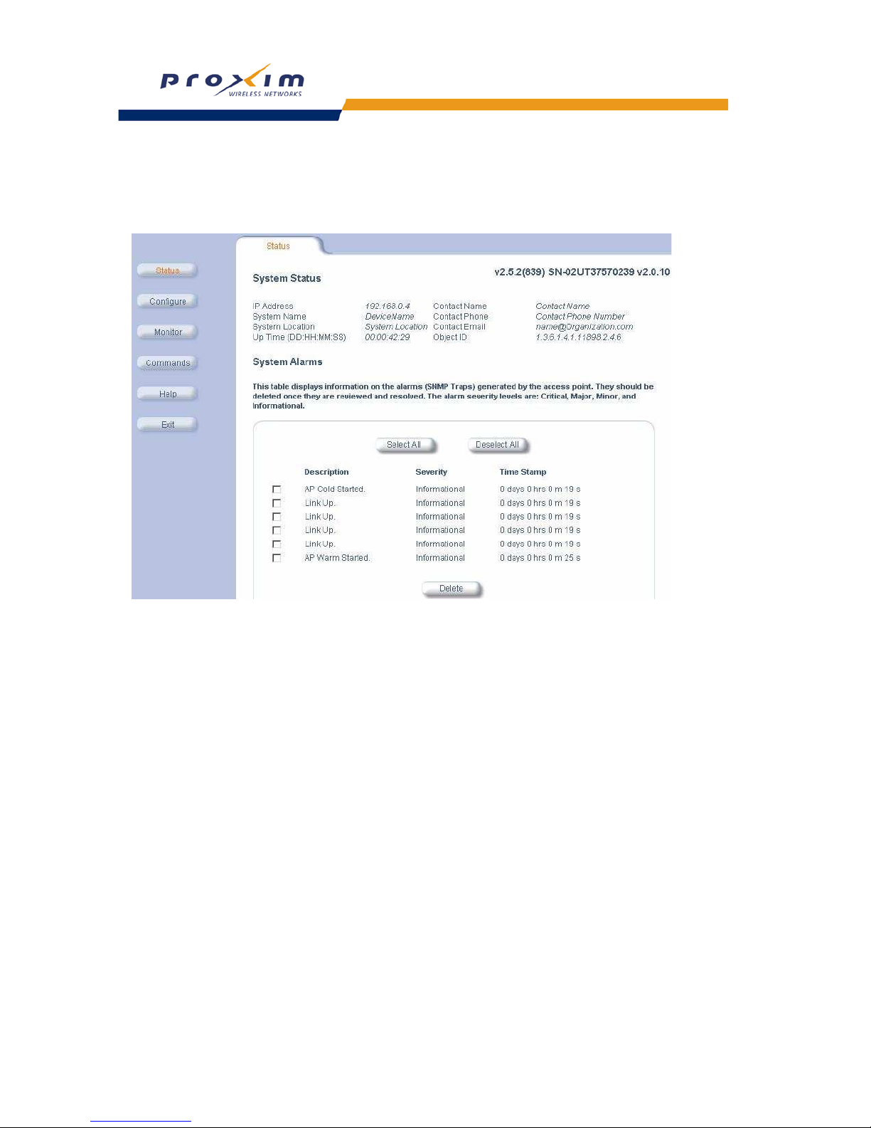
35
Viewing Status Information
System Status
System Status is the first screen to appear each time you connect to the HTTP interface. You can also return to this
screen by clicking the Status button.
Figure 3-2 System Status Screen
Each section of the System Status screen provides the following information:
– System Status: This area provides system level information, including the unit’s IP address and contact
information. See
System for information on these settings.
– System Alarms: System traps (if any) appear in this area. Each trap identifies a specific severity level:
Critical, Major, Minor, and Informational. See Alarms for a list of possible alarms.
Page 38

36
4
Performing Advanced Configuration
• Configuring the AP Using the HTTP/HTTPS Interface
• System: Configure specific system information such as system name and contact information.
• Network: Configure IP settings, DNS client, DHCP server, and Link Integrity.
•
Interfaces: Configure the Access Point’s interfaces: Wireless and Ethernet. Also describes configuring a Wireless
Distribution System (WDS)
.
• Management: Configure the Access Point’s management Passwords, IP Access Table, and Services such as
configuring secure or restricted access to the AP via SNMPv3, HTTPS, or CLI. Configure Secure Management,
SSL, Secure Shell (SSH), and RADIUS Based Access Management. Set up Automatic Configuration for Static IP.
• Filtering: Configure Ethernet Protocol filters, Static MAC Address filters, Advanced filters, and Port filters.
• Alarms: Configure the Alarm (SNMP Trap) Groups, the Alarm Host Table, and the Syslog features.
• Bridge: Configure the Spanning Tree Protocol, Storm Threshold protection, Intra BSS traffic, and Packet
Forwarding.
• RADIUS Profiles: Configure RADIUS features such as RADIUS Access Control and Accounting.
•
SSID/VLAN/Security: Configure security features such as MAC Access Control, WPA, WEP Encryption, and
802.1x. Configure up to 16 VLAN and SSID pairs per wireless interface, and assign Security and RADIUS Profiles
for each pair.
Configuring the AP Using the HTTP/HTTPS Interface
Follow these steps to configure an Access Point’s operating settings using the HTTP/HTTPS interface:
1. Open a Web browser on a network computer.
NOTE
The HTTP interface supports the following Web browser:
• Microsoft Internet Explorer 6 with Service Pack 1 or later
• Netscape 6.1 or later
2. If necessary, disable the Internet proxy settings. For Internet Explorer users, follow these steps:
– Select Tools > Internet Options....
– Click the Connections tab.
– Click LAN Settings....
– If necessary, remove the check mark from the Use a proxy server box.
– Click OK twice to save your changes and return to Internet Explorer.
3. Enter the Access Point’s IP address in the browser ’s Address field and press Enter.
– Result: The Enter Network Password screen appears.
4. Enter the HTTP password in the Password field and click OK. Leave the User Name field blank. (By default, the
HTTP password is “public”).
– Result: The System Status screen appears.
Page 39
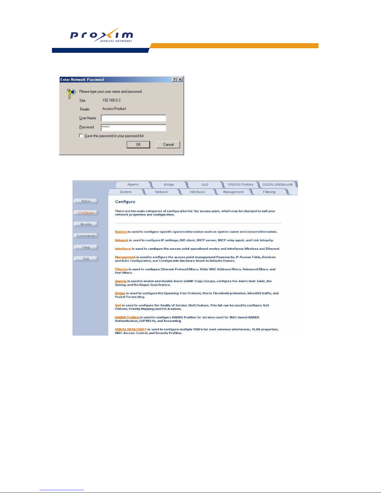
37
Performing Advanced Configuration
Figure 4-1 Enter Network Password Screen
5. Click the Configure button located on the left-hand side of the screen.
Figure 4-2 Configure Main Screen
6. Click the tab that corresponds to the parameter you want to configure. For example, click Network to configure the
Access Point’s TCP/IP settings. The parameters contained in each of the configuration categories are described
later in this chapter.
7. Configure the Access Point’s parameters as necessary. After changing a configuration value, click OK to save the
change.
8. Reboot the Access Point for all of the changes to take effect.
Page 40

38
Performing Advanced Configuration
System
You can configure and view the following parameters within the System Configuration screen:
• Name: The name assigned to the AP. System name must be between 1-31 characters. Refer to the Dynamic DNS
Support
and Access Point System Naming Convention sections for rules on naming the AP.
• Location: The location where the AP is installed. Location must be between 1-255 characters.
• Contact Name: The name of the person responsible for the AP. Name must be between 1-255 characters.
• Contact Email: The email address of the person responsible for the AP. Email must be between 1-255 characters.
• Contact Phone: The telephone number of the person responsible for the AP. Phone must be between 1-255
characters.
• Object ID: This is a read-only field that displays the Access Point’s MIB definition; this information is useful if you
are managing the AP using SNMP.
• Ethernet MAC Address: This is a read-only field that displays the unique MAC (Media Access Control) address
for the Access Point’s Ethernet interface. The MAC address is assigned at the factory.
• Descriptor: This is a read-only field that reports the Access Point’s name, serial number, current image software
version, and current bootloader software version.
• Up Time: This is a read-only field that displays how long the Access Point has been running since its last reboot.
Dynamic DNS Support
DNS is a distributed database mapping the user readable names and IP addresses (and more) of every registered
system on the Internet. Dynamic DNS is a lightweight mechanism which allows for modification of the DNS data of
host systems whose IP addresses change dynamically. Dynamic DNS is usually used in conjunction with DHCP for
assigning meaningful names to host systems whose IP addresses change dynamically.
Access Points provide DDNS support by adding the host name (option 12) in DHCP Client messages, which is used
by the DHCP server to dynamically update the DNS server.
Access Point System Naming Convention
The Access Point's system name is used as its host name. In order to prevent Access Points with default
configurations from registering similar host names in DNS, the default system name of the Access Point is uniquely
generated. Access Points generate unique system names by appending the last 3 bytes of the Access Point's MAC
address to the default system name.
The system name must be compliant with the encoding rules for host name as per DNS RFC 1123. The DNS host
name encoding rules are:
• Characters have to be alphanumeric or hyphen.
• The name cannot start or end with a hyphen.
• The name cannot start with a digit.
• The number of characters has to be 63 or less. (Currently the system name length is limited to 32 bytes).
Image upgrades could cause the system to boot with an older system name format that is not DNS compliant. To
prevent problems with dynamic DNS after an image upgrade, the system name will automatically be converted to a
DNS compliant system name.
The rules of conversion of older system names are:
• If the length is greater than 63 then the string is truncated. (This will not happen since the system name is anyway
limited to 31 bytes)
• All invalid characters at the beginning or end of the string are replaced with the character 'X'.
• All other invalid characters are replaced with hyphens.
Page 41

39
Performing Advanced Configuration
Network
The Network tab contains three sub-tabs.
– IP Configuration
– DHCP Server
– Link Integrity
IP Configuration
You can configure and view the following parameters within the IP Configuration screen:
NOTE
You must reboot the Access Point in order for any changes to the Basic IP or DNS Client parameters take
effect.
Basic IP Parameters
• IP Address Assignment Type: Set this parameter to Dynamic to configure the Access Point as a Dynamic Host
Configuration Protocol (DHCP) client; the Access Point will obtain IP settings from a network DHCP server
automatically during boot-up. If you do not have a DHCP server or if you want to manually configure the
Access Point’s IP settings, set this parameter to Static.
• IP Address: The Access Point’s IP address. When IP Address Assignment Type is set to Dynamic, this field is
read-only and reports the unit’s current IP address. The Access Point will default to 169.254.128.132 if it cannot
obtain an address from a DHCP server.
• Subnet Mask: The Access Point’s subnet mask. When IP Address Assignment Type is set to Dynamic, this field is
read-only and reports the unit’s current subnet mask. The subnet mask will default to 255.255.0.0 if the unit cannot
obtain one from a DHCP server.
• Gateway IP Address: The IP address of the Access Point’s gateway. When IP Address Assignment Type is set to
Dynamic, this field is read-only and reports the IP address of the unit’s gateway. The gateway IP address will
default to 169.254.128.133 if the unit cannot obtain an address from a DHCP server.
DNS Client
If you prefer to use host names to identify network servers rather than IP addresses, you can configure the AP to act
as a Domain Name Service (DNS) client. When this feature is enabled, the Access Point contacts the network’s DNS
server to translate a host name to the appropriate network IP address. You can use this DNS Client functionality to
identify RADIUS servers by host name. See
RADIUS Profiles for details.
• Enable DNS Client: Place a check mark in the box provided to enable DNS client functionality. Note that this
option must be enabled before you can configure the other DNS Client parameters.
• DNS Primary Server IP Address: The IP address of the network’s primary DNS server.
• DNS Secondary Server IP Address: The IP address of a second DNS server on the network. The Access Point
will attempt to contact the secondary server if the primary server is unavailable.
• DNS Client Default Domain Name: The default domain name for the Access Point’s network (for example,
“proxim.com”). Contact your network administrator if you need assistance setting this parameter.
Advanced
• Default TTL (Time to Live): Time to Live (TTL) is a field in an IP packet that specifies how long in seconds the
packet can remain active on the network. The Access Point uses the default TTL for packets it generates for which
the transport layer protocol does not specify a TTL value. This parameter supports a range from 0 to 65535. By
default, TTL is 64.
Page 42
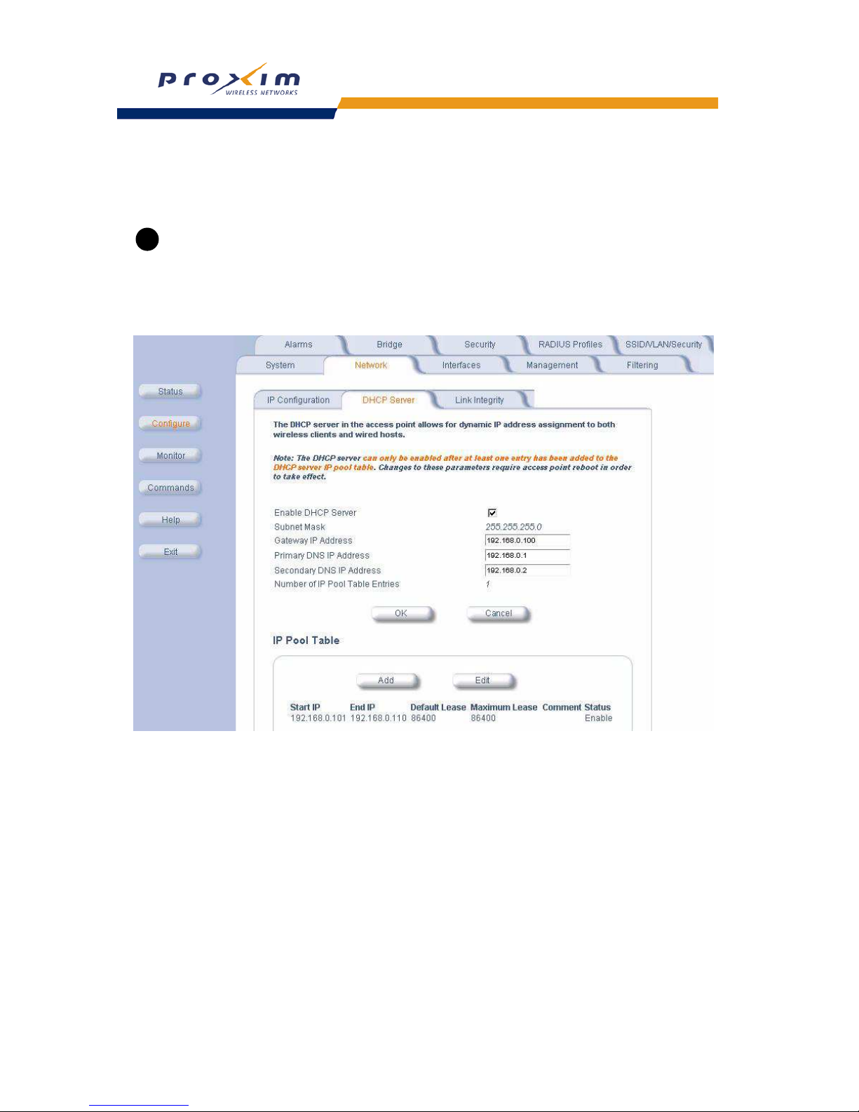
40
Performing Advanced Configuration
DHCP Server
If your network does not have a DHCP Server, you can configure the AP as a DHCP server to assign dynamic IP
addresses to Ethernet nodes and wireless clients.
CAUTION
!
Make sure there are no other DHCP servers on the network and do not enable the DHCP server without
checking with your network administrator first, as it could bring down the whole network. Also, the AP must be
configured with a static IP address before enabling this feature.
When the DHCP Server functionality is enabled, you can create one or more IP address pools from which to assign
addresses to network devices.
Figure 4-3 DHCP Server Configuration Screen
Page 43

41
Performing Advanced Configuration
You can configure and view the following parameters within the DHCP Server Configuration screen:
• Enable DHCP Server: Place a check mark in the box provided to enable DHCP Server functionality.
NOTE
You cannot enable the DHCP Server functionality unless there is at least one IP Pool Table Entry configured.
• Subnet Mask: This field is read-only and reports the Access Point’s current subnet mask. DHCP clients that
receive dynamic addresses from the AP will be assigned this same subnet mask.
• Gateway IP Address: The AP will assign the specified address to its DHCP clients.
• Primary DNS IP Address: The AP will assign the specified address to its DHCP clients.
• Secondary DNS IP Address: The AP will assign the specified address to its DHCP clients.
• Number of IP Pool Table Entries: This is a read-only field that reports the number of IP address pools currently
configured.
• IP Pool Table Entry: This entry specifies a range of IP addresses that the AP can assign to its wireless clients.
The maximum number of entries allowed is 20. Click Add to create a new entry. Click Edit to change an existing
entry. Each entry contains the following field:
– Start IP Address
– End IP Address
– Default Lease Time (optional): The default time value for clients to retain the assigned IP address. DHCP
automatically renews IP Addresses without client notification. This parameter supports a range between 3600
and 86400 seconds. The default is 86400 seconds.
– Maximum Lease Time (optional): The maximum time value for clients to retain the assigned IP address.
DHCP automatically renews IP Addresses without client notification. This parameter supports a range
between 3600 and 86400 seconds. The default is 86400 seconds.
– Comment (optional)
– Status: IP Pools are enabled upon entry in the table. You can also disable or delete entries by changing this
field’s value.
NOTE
You must reboot the Access Point before changes to any of these DHCP server parameters take effect.
Link Integrity
The Link Integrity feature checks the link between the AP and the nodes on the Ethernet backbone. These nodes are
listed by IP address in the Link Integrity IP Address Table. The AP periodically pings the nodes listed within the table. If
the AP loses network connectivity (that is, the ping attempts fail), the AP disables its wireless interface until the
connection is restored. This forces the unit’s wireless clients to switch to another Access Point that still has a network
connection. Note that this feature does not affect WDS links (if applicable).
You can configure and view the following parameters within the Link Integrity Configuration screen:
• Enable Link Integrity: Place a check mark in the box provided to enable Link Integrity.
• Poll Interval (milliseconds): The interval between link integrity checks. Range is 500 - 15000 ms in increments of
500 ms; default is 500 ms.
• Poll Retransmissions: The number of times a poll should be retransmitted before the link is considered down.
Range is 0 to 255; default is 5.
• Target IP Address Entry: This entry specifies the IP address of a host on the network that the AP will periodically
poll to confirm connectivity. The table can hold up to five entries. By default, all five entries are set to 0.0.0.0. Click
Edit to update one or more entries. Each entry contains the following field:
– Target IP Address
– Comment (optional)
– Status: Set this field to Enable to specify that the Access Point should poll this device. You can also disable
an entry by changing this field’s value to Disable.
Page 44
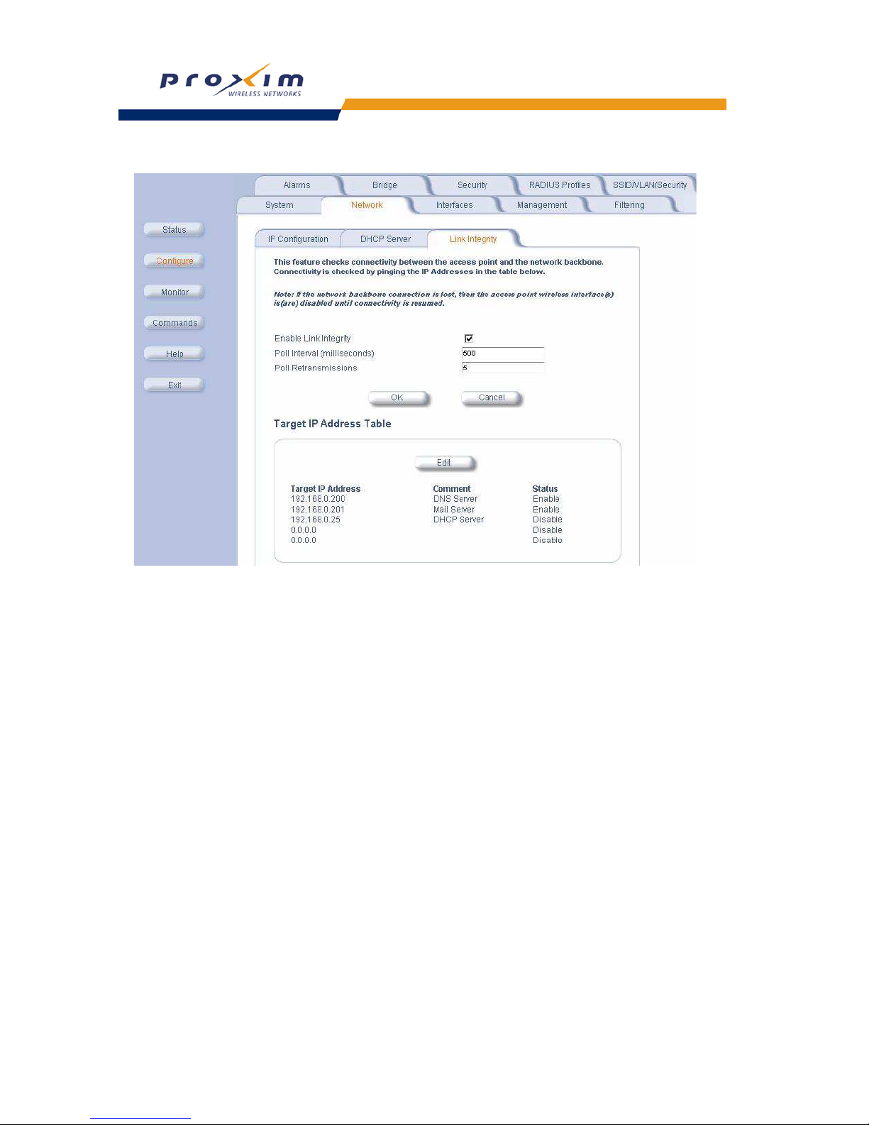
42
Performing Advanced Configuration
Figure 4-4 Link Integrity Configuration Screen
Interfaces
The Interfaces tab contains the following sub-tabs:
– Operational Mode
– 8Wireless-A and Wireless-B
– Ethernet
From these sub-tabs, you configure the Access Point’s operational mode, wireless interface settings and Ethernet
settings. You may also configure a
Wireless Distribution System (WDS) for AP-to-AP communications.
For the wireless interface configuration, refer to the wireless parameters below that correspond to your radio type.
– Wireless A (802.11a)
– Wireless (802.11b)
– Wireless (802.11b/g)
– Wireless (802.11a/g)
Page 45

43
Performing Advanced Configuration
Operational Mode
Operational Mode Selection
You can configure and view the following parameters within the Operational Mode screen.
• Operational Mode: the mode of communication between the wireless clients and the Access Point:
• 802.11b only
• 802.11g only
• 802.11bg
• 802.11a
• 802.11g-wifi
IEEE 802.11d Support for Additional Regulatory Domains
The IEEE 802.11d specification allows conforming equipment to operate in more than one regulatory domain over
time. IEEE 802.11d support allows the AP to broadcast its radio’s regulatory domain information in its beacon and
probe responses to clients. This allows clients to passively learn what country they are in and only transmit in the
allowable spectrum. When a client enters a regulatory domain, it passively scans to learn at least one valid channel,
i.e., a channel upon which it detects IEEE Standard 802.11 frames.
The beacon frame contains information on the country code, the maximum allowable transmit power, and the channels
to be used for the regulatory domain.
The same information is transmitted in probe response frames in response to a client’s probe requests. Once the client
has acquired the information required to meet the transmit requirements of the regulatory domain, it configures itself
for operation in the regulatory domain.
The Wireless NIC determines the regulatory domain the AP is operating in. Depending on the regulatory domain, a
default country code is chosen that is transmitted in the beacon and probe response frames.
Configuring 802.11d Support
Perform the following procedure to enable 802.11d support, and select the country code:
1. Click Configure > Interfaces > Operational Mode.
2. Select Enable 802.11d.
3. Select the Country Code from the ISO/IEC 3166-1 CountryCode drop-down menu.
4. Click OK.
5. Configure Transmit Power Control and transmit power level if required.
TX Power Control
Transmit Power Control uses standard 802.11d frames to control transmit power within an infrastructure BSS. This
method of power control is considered to be an interim way of controlling the transmit power of 802.11d enabled clients
in lieu of implementation of 802.11h.
The Transmit Power Control feature lets the user configure the transmit power level of the wireless interface at one of
four levels:
• 100% of the maximum transmit power level defined by the regulatory domain
• 50%
• 25%
• 12.5%
When Transmit Power Control is enabled, the transmit power level of the card in the AP is set to the configured
transmit power level. The power level is advertised in Beacon and Probe Response frames as the 802.11d maximum
transmit power level.
When an 802.11d-enabled client learns the regulatory domain related information from Beacon and Probe Response
frames, it learns the power level advertised in Beacon and Probe response frames as the maximum transmit power of
the regulatory domain and configures itself to operate with that power level.
As a result, the transmit power level of the BSS is configured to the power level set in the AP (assuming that the BSS
has only 802.11d enabled clients and an 802.11d enabled AP).
Page 46
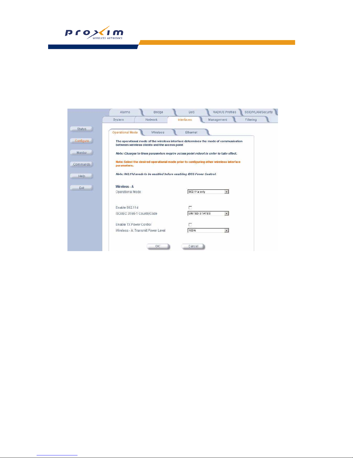
44
Performing Advanced Configuration
Configuring TX Power Control
1. Click Configure > Interfaces > Operational Mode.
2. Select Enable Transmit Power Control.
3. Select the transmit power level for interface A from the Wireless-A: Transmit Power Level drop-down menu.
4. Click OK.
8
Figure 4-5 Operational Mode
Wireless
Wireless A (802.11a)
You can configure and view the following parameters within the Wireless Interface Configuration screen for an
802.11a AP:
Page 47
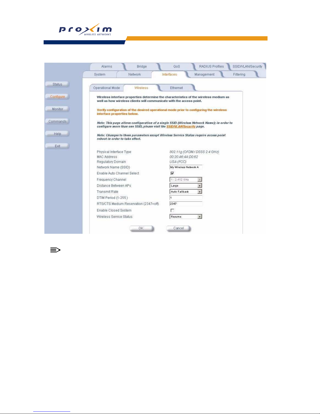
45
Performing Advanced Configuration
Abbildung 4-6 Wireless Interface Sub-tab
NOTE
You must reboot the Access Point before any changes to these parameters take effect.
• Physical Interface Type: For an 802.11a AP, this field reports: “802.11a (OFDM 5 GHz).” OFDM stands for
Orthogonal Frequency Division Multiplexing; this is the name for the radio technology used by 802.11a devices.
• MAC Address: This is a read-only field that displays the unique MAC (Media Access Control) address for the
Access Point’s wireless interface. The MAC address is assigned at the factory.
• Regulatory Domain: Reports the regulatory domain for which the AP is certified. Not all features or channels are
available in all countries. The available regulatory domains include:
— FCC - U.S./Canada, Mexico, and Australia
— ETSI - Europe and the United Kingdom
— TELEC: Japan
— SG: Singapore
— ASIA: China and South Korea
— TW: Taiwan and Hong Kong
• Network Name (SSID): Enter a Network Name (between 1 and 32 characters long) for the wireless network. You
must configure each wireless client to use this name as well.
• Auto Channel Select: The AP scans the area for other Access Points and selects a free or relatively unused
communication channel. This helps prevent interference problems and increases network performance. By default
this feature is enabled. See
802.11a Channel Frequencies for a list of Channels.
Page 48

46
Performing Advanced Configuration
NOTE
You cannot disable Auto Channel Select for 802.11a products in Europe (see Dynamic Frequency Selection
(DFS) for details).
• Frequency Channel: When Auto Channel Select is enabled, this field is read-only and displays the Access Point’s
current operating Channel. When Auto Channel Select is disabled, you can specify the Access Point’s channel. If
you decide to manually set the unit’s Channel, ensure that nearby devices do not use the same frequency.
Available Channels vary based on regulatory domain. See
802.11a Channel Frequencies. Note that you cannot
manually set the channel for 802.11a products in Europe (see Dynamic Frequency Selection (DFS) for details).
• Transmit Rate: Use the drop-down menu to select a specific transmit rate for the AP. Choose a particular rate
available for protocol being used or Auto Fallback. Auto Fallback is the default setting; it allows the AP unit to
select the best transmit rate based on the cell size.
• DTIM Period: The Deferred Traffic Indicator Map (DTIM) is used with clients that have power management
enabled. DTIM should be left at 1, the default value, if any clients have power management enabled. This
parameter supports a range between 1 and 255.
• RTS/CTS Medium Reservation: This parameter affects message flow control and should not be changed under
normal circumstances. Range is 0 to 2347. When set to a value between 0 and 2347, the Access Point uses the
RTS/CTS mechanism for packets that are the specified size or greater. When set to 2347 (the default setting),
RTS/CTS is disabled. See
RTS/CTS Medium Reservation for more information.
• Closed System: Check this box to allow only clients configured with the Access Point’s specific Network Name to
associate with the Access Point. When enabled, a client configured with the Network Name “ANY” cannot connect
to the AP. This option is disabled by default. See Broadcast SSID and Closed System for more information.
• Wireless Service Status: Select shutdown to shutdown the wireless service on a wireless interface, or resume
to resume wireless service. See Wireless Service Status for more information.
Dynamic Frequency Selection (DFS)
802.11a APs sold in Europe use a technique called Dynamic Frequency Selection (DFS) to automatically select an
operating channel. During boot-up, the AP scans the available frequency and selects a channel that is free of
interference. If the AP subsequently detects interference on its channel, it automatically reboots and selects another
channel that is free of interference.
DFS only applies to 802.11a APs used in Europe (i.e., units whose regulatory domain is set to ETSI). The European
Telecommunications Standard Institute (ETSI) requires that 802.11a devices use DFS to prevent interference with
radar systems and other devices that already occupy the 5 GHz band.
If you are using an 802.11a AP in Europe, keep in mind the following:
• DFS is not a configurable parameter. It is always enabled and cannot be disabled.
• You cannot manually select the device’s operating channel; you must let DFS select the channel.
• You cannot configure the Auto Channel Select option. Within the HTTP interface, this option always appears
enabled.
RTS/CTS Medium Reservation
The 802.11 standard supports optional RTS/CTS communication based on packet size. Without RTS/CTS, a sending
radio listens to see if another radio is already using the medium before transmitting a data packet. If the medium is
free, the sending radio transmits its packet. However, there is no guarantee that another radio is not transmitting a
packet at the same time, causing a collision. This typically occurs when there are hidden nodes (clients that can
communicate with the Access Point but are out of range of each other) in very large cells.
When RTS/CTS occurs, the sending radio first transmits a Request to Send (RTS) packet to confirm that the medium
is clear. When the receiving radio successfully receives the RTS packet, it transmits back a Clear to Send (CTS)
packet to the sending radio. When the sending radio receives the CTS packet, it sends the data packet to the receiving
radio. The RTS and CTS packets contain a reservation time to notify other radios (including hidden nodes) that the
medium is in use for a specified period. This helps to minimize collisions. While RTS/CTS adds overhead to the radio
network, it is particularly useful for large packets that take longer to resend after a collision occurs.
RTS/CTS Medium Reservation is an advanced parameter and supports a range between 0 and 2347 bytes. When set
to 2347 (the default setting), the RTS/CTS mechanism is disabled. When set to 0, the RTS/CTS mechanism is used for
all packets. When set to a value between 0 and 2347, the Access Point uses the RTS/CTS mechanism for packets that
Page 49

47
Performing Advanced Configuration
are the specified size or greater. You should not need to enable this parameter for most networks unless you suspect
that the wireless cell contains hidden nodes.
Wireless Service Status
The user can shutdown (or resume) the wireless service on the wireless interface of the AP through the CLI, HTTP, or
SNMP interface. When the wireless service on a wireless interface is shutdown, the AP will:
• Stop the AP services to wireless clients connected on that wireless interface by disassociating them
• Disable the associated BSS ports on that interface
• Disable the transmission and reception of frames on that interface
• Indicate the wireless service shutdown status of the wireless interface through LED and traps
• Enable Ethernet interface so that it can receive a wireless service resume command through CLI/HTTP/SNMP
interface
NOTE
WSS disables only BSS ports; WDS ports are still operational.
In shutdown state, AP will not transmit and receive frames from the wireless interface and will stop transmitting
periodic beacons. Moreover, none of the frames received from the Ethernet interface will be forwarded to that wireless
interface.
Wireless service on a wireless interface of the AP can be resumed through CLI/HTTP/SNMP management interface.
When wireless service on a wireless interface is resumed, the AP will:
• Enable the transmission and reception of frames on that wireless interface
• Enable the associated BSS port on that interface
• Start the AP services to wireless clients
• Indicate the wireless service resume status of the wireless interface through LED and traps
After wireless service resumes, the AP resumes beaconing, transmitting and receiving frames to/from the wireless
interface and bridging the frames between the Ethernet and the wireless interface.
Traps Generated During Wireless Service Shutdown (and Resume)
The following traps are generated during wireless service shutdown and resume, and are also sent to any configured
Syslog server.
When the wireless service is shutdown on a wireless interface, the AP generates a trap called
oriTrapWirelessServiceShutdown.
When the wireless service is resumed on a wireless interface, the AP generate a trap called
oriTrapWirelessServiceResumed.
Wireless Interface Activity LED and Wireless Service Shutdown
When the wireless service is shutdown on a wireless interface, the Wireless Interface Activity LED for that interface
changes to an amber color.
When wireless service is resumed on a wireless interface, the Wireless Interface Activity LED for that interface
maintains an OFF state while there is no wireless link activity and changes to green color when there is wireless link
activity.
Wireless (802.11b)
You can configure and view the following parameters within the Wireless Interface Configuration screen for an
802.11b AP:
NOTE
You must reboot the Access Point before any changes to these parameters take effect.
• Physical Interface Type: For 802.11b AP, this field reports: “802.11b (DSSS 2.4 GHz).” DSSS stands for Direct
Sequence Spread Spectrum; this is the name for the radio technology used by 802.11b devices.
• MAC Address: This is a read-only field that displays the unique MAC (Media Access Control) address for the
Access Point’s wireless interface. The MAC address is assigned at the factory.
Page 50

48
Performing Advanced Configuration
• Regulatory Domain: Reports the regulatory domain for which the AP is certified. Not all features or channels are
available in all countries. The available regulatory domains include:
— FCC - U.S./Canada, Mexico, and Australia
— ETSI - Most of Europe, including the United Kingdom, Ireland, Singapore, and Hong Kong
— TELEC: Japan
— IL - Israel
• Network Name (SSID): Enter a Network Name (between 1 and 32 characters long) for the wireless network. You
must configure each wireless client to use this name as well.
• Auto Channel Select: The AP scans the area for other Access Points and selects a free or relatively unused
communication channel. This helps prevent interference problems and increases network performance. By default
this feature is enabled; see 802.11b Channel Frequencies for a list of Channels. However, if you are setting up a
Wireless Distribution System (WDS), it must be disabled. See Wireless Distribution System (WDS) for more
information.
• Frequency Channel: When Auto Channel Select is enabled, this field is read-only and displays the Access Point’s
current operating channel. When Auto Channel Select is disabled, you can specify the Access Point’s operating
channel. If you decide to manually set the unit’s channel, ensure that nearby devices do not use the same
frequency (unless you are setting up a WDS). Available Channels vary based on regulatory domain. See
802.11b
Channel Frequencies
.
• Distance Between APs: Set to Large, Medium, Small, Microcell, or Minicell depending on the site survey for
your system. By default, this parameter is set to Large. The distance value is related to the Multicast Rate
(described next). In general, a larger distance between APs means that your clients operate a slower data rates
(on average). This feature is available only if you are using an Orinoco Classic Gold card. See Distance Between
APs
for more information.
• Multicast Rate: Sets the rate at which Multicast messages are sent. This value is related to the Distance Between
APs parameter (described previously). The table below displays the possible Multicast Rates based on the
Distance between APs setting. By default, this parameter is set to 2 Mbits/sec. This feature is available only if you
are using an Orinoco Classic Gold card. See Multicast Rate for more information.
• DTIM Period: The Deferred Traffic Indicator Map (DTIM) is used with clients that have power management
enabled. DTIM should be left at 1, the default value, if any clients have power management enabled. This
parameter supports a range between 1 and 255.
• RTS/CTS Medium Reservation: This parameter affects message flow control and should not be changed under
normal circumstances. Range is 0 to 2347. When set to a value between 0 and 2347, the Access Point uses the
RTS/CTS mechanism for packets that are the specified size or greater. When set to 2347 (the default setting),
RTS/CTS is disabled. See
RTS/CTS Medium Reservation for more information.
• Interference Robustness: Enable this option if other electrical devices in the 2.4 GHz frequency band (such as a
microwave oven or a cordless phone) may be interfering with the wireless signal. The AP will automatically
fragment large packets into multiple smaller packets when interference is detected to increase the likelihood that
the messages will be received in the presence of interference. The receiving radio reassembles the original packet
once all fragments have been received. This feature is available only if you are using an Orinoco Classic Gold
card. This option is disabled by default.
• Closed System: Check this box to allow only clients configured with the Access Point’s specific Network Name to
associate with the Access Point. When enabled, a client configured with the Network Name “ANY” cannot connect
to the AP. This option is disabled by default. See
Broadcast SSID and Closed System for more information.
• Wireless Service Status: Select shutdown to shutdown the wireless service on a wireless interface, or resume
to resume wireless service. See
Wireless Service Status for more information.
• Load Balancing: Enable this option so clients can evaluate which Access Point to associate with, based on
current AP loads. This feature is enabled by default; it helps distribute the wireless load between APs. This feature
is not available if you are using an ORiNOCO ComboCard or a non-ORiNOCO client with the AP.
Distance between APs Multicast Rate
Large 1 and 2 Mbits/sec
Medium 1, 2, and 5.5 Mbits/sec
Small 1, 2, 5.5 and 11 Mbits/sec
Minicell 1, 2, 5.5 and 11 Mbits/sec
Microcell 1, 2, 5.5 and 11 Mbits/sec
Page 51
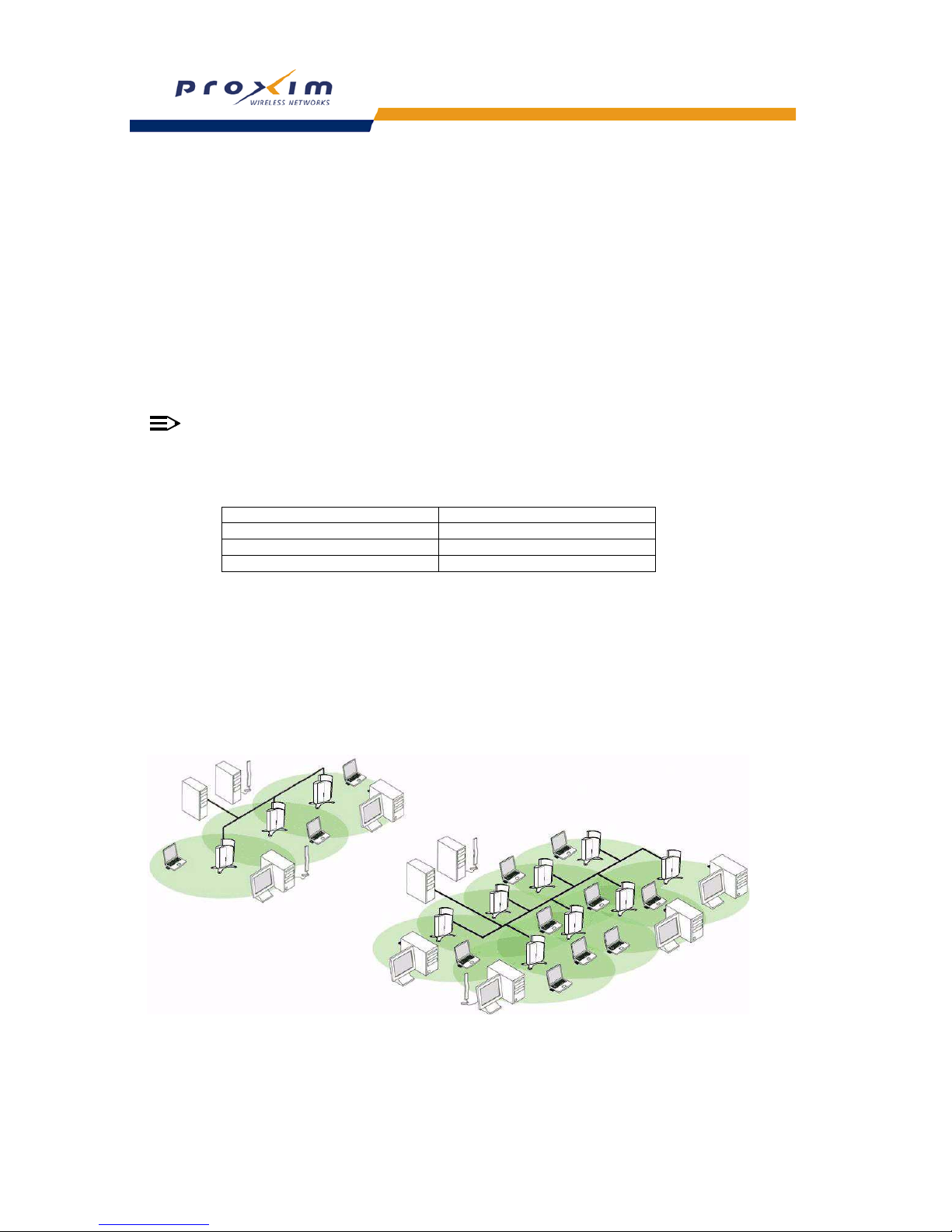
49
Performing Advanced Configuration
• Medium Density Distribution: When enabled, the Access Point automatically notifies wireless clients of its
Distance Between APs, Interference Robustness, and RTS/CTS Medium Reservation settings. This feature is
enabled by default and allows clients to automatically adopt the values used by its current Access Point (even if
these values differ from the client’s default values or from the values supported by other Access Points). Note that
this feature is available only if you are using an Orinoco Classic Gold card. Proxim recommends that you leave this
parameter enabled, particularly if you have ORiNOCO clients on your wireless network (leaving this parameter
enabled should not adversely affect the performance of any ORiNOCO ComboCards or non-ORiNOCO cards on
your network).
Distance Between APs
Distance Between APs defines how far apart (physically) your AP devices are located, which in turn determines the
size of your cell. Cells of different sizes have different capacities and, therefore, suit different applications. For
instance, a typical office has many stations that require high bandwidth for complex, high-speed data processing. In
contrast, a typical warehouse has a few forklifts requiring low bandwidth for simple transactions.
NOTE
This feature is available only if you are using an Orinoco Classic Gold card.
Cell capacities are compared in the following table, which shows that small cells suit most offices and large cells suit
most warehouses:
Coverage
The number of Access Points in a set area determines the network coverage for that area. A large number of
Access Points covering a small area is a high-density cell. A few Access Points, or even a single unit, covering the
same small area would result in a low-density cell, even though in both cases the actual area did not change — only
the number of Access Points covering the area changed.
In a typical office, a high density area consists of a number of Access Points installed every 20 feet and each
Access Point generates a small radio cell with a diameter of about 10 feet. In contrast, a typical warehouse might have
a low density area consisting of large cells (with a diameter of about 90 feet) and Access Points installed every
200 feet.
Figure 4-7 Low Density vs. Ultra High Density Network
The Distance Between Cells parameter supports five values: Large, Medium, Small, Minicell, and Microcell.
Small Cell Large Cell
Physically accommodates few stations Physically accommodates many stations
High cell bandwidth per station Lower cell bandwidth per station
High transmit rate Lower transmit rate
Page 52

50
Performing Advanced Configuration
CAUTION
!
The distance between APs should not be approximated. It is calculated by means of a manual Site Survey, in
which an AP is set up and clients are tested throughout the area to determine signal strength and coverage,
and local limits such as physical interference are investigated. From these measurements the appropriate cell
size and density is determined, and the optimum distance between APs is calculated to suit your particular
business requirements. Contact your reseller for information on how to conduct a Site Survey.
Multicast Rate
The multicast rate determines the rate at which broadcast and multicast packets are transmitted by the Access Point to
the wireless network. Stations that are closer to the Access Point can receive multicast packets at a faster data rate
than stations that are farther away from the AP. Therefore, you should set the Multicast Rate based on the size of the
Access Point’s cell. For example, if the Access Point’s cell is very small (e.g., Distance Between APs is set to
Microcell), you can expect that all stations should be able to successfully receive multicast packets at 11 MBits/sec so
you can set Multicast Rate to 11 Mbits/sec. However, if the Access Point’s cell is large, you need to accommodate
stations that may not be able to receive multicast packets at the higher rates; in this case, you should set Multicast
Rate to 1 or 2 Mbits/sec.
Figure 4-8 1 Mbits/s and 11 Mbits/s Multicast Rates
NOTE
There is an inter-dependent relationship between the Distance between APs and the Multicast Rate. In
general, larger systems operate at a lower average transmit rate. The variation between Multicast Rate and
Distance Between APs is presented in the following table:
1.0 Mbit/s 2.0 Mbits/s 5.5 Mbits/s 11 Mbits/s
Large yes yes
Medium yes yes yes
Small yes yes yes yes
Minicell yes yes yes yes
Microcell yes yes yes yes
11 Mbits/s
1 Mbit/s
Page 53

51
Performing Advanced Configuration
The Distance Between APs must be set before the Multicast Rate, because when you select the Distance
Between APs, the appropriate range of Multicast values automatically populates the drop-down menu. This
feature is not available if you are using an ORiNOCO ComboCard or a non-ORiNOCO client with the AP.
Wireless (802.11b/g)
You can configure the following radio parameters for an 802.11b/g AP:
NOTE
You must reboot the Access Point before any changes to these parameters take effect.
• Operational Mode: An 802.11b/g wireless interface can be configured to operate in the following modes:
– 802.11b mode only: The radio uses the 802.11b standard only.
– 802.11g mode only: The radio is optimized to communicate with 802.11g devices. This setting will provide the
best results if this radio interface will only communicate with 802.11g devices.
– 802.11b/g mode: This is the default mode. Use this mode if you want to support a mix of 802.11b and 802.11g
devices.
– 802.11g-wifi: This mode was developed for Wi-Fi compliance testing purposes. It is similar to 802.11g only
mode.
In general, you should use either 802.11g only mode (if you want to support 802.11g devices only) or 802.11b/g
mode to support a mix of 802.11b and 802.11g devices.
• Physical Interface Type: Depending on the Operational Mode, this field reports:
– For 802.11b mode only: "802.11b (CCK/DSSS 2.4 GHz)"
– For 802.11g and 802.11g-wifi modes: "802.11g (OFDM/DSSS 2.4 GHz)"
– For 802.11b/g mode: "802.11b/g (ERP-CCK/DSSS/OFDM 2.4 GHz)"
OFDM stands for Orthogonal Frequency Division Multiplexing; this is the name for the radio technology used by
802.11a devices. DSSS stands for Direct Sequence Spread Spectrum; this is the name for the radio technology
used by 802.11b devices.
• MAC Address: This is a read-only field that displays the unique MAC (Media Access Control) address for the
Access Point’s wireless interface. The MAC address is assigned at the factory.
• Regulatory Domain: Reports the regulatory domain for which the AP is certified. Not all features or channels are
available in all countries. The available regulatory domains include:
— FCC - U.S./Canada, Mexico, and Australia
— ETSI - Europe, including the United Kingdom
— TELEC - Japan
— IL - Israel
• Network Name (SSID): Enter a Network Name (between 1 and 32 characters long) for the wireless network. You
must configure each wireless client to use this name as well.
• Auto Channel Select: The AP scans the area for other Access Points and selects a free or relatively unused
communication channel. This helps prevent interference problems and increases network performance. By default
this feature is enabled; see 802.11g Channel Frequencies for a list of Channels.
• Frequency Channel: When Auto Channel Select is enabled, this field is read-only and displays the Access Point’s
current operating channel. When Auto Channel Select is disabled, you can specify the Access Point’s operating
channel. If you decide to manually set the unit’s channel, ensure that nearby devices do not use the same
frequency (unless you are setting up a WDS). Available Channels vary based on regulatory domain. See
802.11g
Channel Frequencies.
• Transmit Rate: Select a specific transmit rate for the AP. The values available depend on the Operational Mode.
Auto Fallback is the default setting; it allows the AP to select the best transmit rate based on the cell size.
— For 802.11b only -- Auto Fallback, 1, 2, 5.5, 11 Mbits/sec
— For 802.11g only -- Auto Fallback, 6, 9, 12, 18, 24, 36, 48, 54 Mbits/sec
— For 802.11b/g and 802.11g-wifi -- Auto Fallback, 1, 2, 5.5, 6, 9, 11, 12, 18, 24, 36, 48, 54 Mbits/sec
• DTIM Period: The Deferred Traffic Indicator Map (DTIM) is used with clients that have power management
enabled. DTIM should be left at 1, the default value, if any clients have power management enabled. This
parameter supports a range between 1 and 255.
Page 54

52
Performing Advanced Configuration
• RTS/CTS Medium Reservation: This parameter affects message flow control and should not be changed under
normal circumstances. Range is 0 to 2347. When set to a value between 0 and 2347, the Access Point uses the
RTS/CTS mechanism for packets that are the specified size or greater. When set to 2347 (the default setting),
RTS/CTS is disabled. See RTS/CTS Medium Reservation for more information.
• Closed System: Check this box to allow only clients configured with the Access Point’s specific Network Name to
associate with the Access Point. When enabled, a client configured with the Network Name "ANY” cannot connect
to the AP. This option is disabled by default. See
Broadcast SSID and Closed System for more information.
Wireless (802.11a/g)
You can configure and view the following parameters within the Wireless Interface Configuration screen for an
802.11a/g AP:
NOTE
You must reboot the Access Point before any changes to these parameters take effect.
• Operational Mode: An 802.11b/g wireless interface can be configured to operate in the following modes:
– 802.11b mode only: The radio uses the 802.11b standard only.
– 802.11g mode only: The radio is optimized to communicate with 802.11g devices. This setting will provide the
best results if this radio interface will only communicate with 802.11g devices.
– 802.11a mode only: The radio uses the 802.11a standard only.
– 802.11b/g mode: This is the default mode. Use this mode if you want to support a mix of 802.11b and 802.11g
devices.
– 802.11g-wifi: This mode was developed for Wi-Fi compliance testing purposes. It is similar to 802.11g only
mode.
In general, you should use either 802.11g only mode (if you want to support 802.11g devices only) or 802.11b/g
mode to support a mix of 802.11b and 802.11g devices.
• Physical Interface Type: Depending on the Operational Mode, this field reports:
– For 802.11b mode only: "802.11b (CCK/DSSS 2.4 GHz)"
– For 802.11g and 802.11g-wifi modes: "802.11g (OFDM/DSSS 2.4 GHz)"
– For 802.11b/g mode: "802.11b/g (ERP-CCK/DSSS/OFDM 2.4 GHz)"
– For 802.11a mode only, this field reports: “802.11a (OFDM 5 GHz).”
OFDM stands for Orthogonal Frequency Division Multiplexing; this is the name for the radio technology used by
802.11a devices. DSSS stands for Direct Sequence Spread Spectrum; this is the name for the radio technology
used by 802.11b devices.
• MAC Address: This is a read-only field that displays the unique MAC (Media Access Control) address for the
Access Point’s wireless interface. The MAC address is assigned at the factory.
• Regulatory Domain: Reports the regulatory domain for which the AP is certified. Not all features or channels are
available in all countries. The available regulatory domains include:
— FCC - U.S./Canada, Mexico, and Australia
— ETSI - Europe and the United Kingdom
— TELEC: Japan
— SG: Singapore
— ASIA: China, Hong Kong, and South Korea
— TW: Taiwan
— FCC - U.S./Canada, Mexico, and Australia
— ETSI - Europe and the United Kingdom
— TELEC: Japan
— SG: Singapore
— ASIA: China and South Korea
— TW: Taiwan and Hong Kong
• Network Name (SSID): Enter a Network Name (between 1 and 32 characters long) for the wireless network. You
must configure each wireless client to use this name as well.
Page 55

53
Performing Advanced Configuration
• Auto Channel Select: The AP scans the area for other Access Points and selects a free or relatively unused
communication channel. This helps prevent interference problems and increases network performance. By default
this feature is enabled. See
802.11a Channel Frequencies and 802.11g Channel Frequencies for a list of
Channels.
NOTE
You cannot disable Auto Channel Select for 802.11a products in Europe (see Dynamic Frequency Selection
(DFS) for details).
• Frequency Channel: When Auto Channel Select is enabled, this field is read-only and displays the Access Point’s
current operating Channel. When Auto Channel Select is disabled, you can specify the Access Point’s channel. If
you decide to manually set the unit’s Channel, ensure that nearby devices do not use the same frequency.
Available Channels vary based on regulatory domain. See
802.11a Channel Frequencies and 802.11g Channel
Frequencies. Note that you cannot manually set the channel for 802.11a products in Europe (see Dynamic
Frequency Selection (DFS) for details).
• Transmit Rate: Select a specific transmit rate for the AP. The values available depend on the Operational Mode.
Auto Fallback is the default setting; it allows the AP to select the best transmit rate based on the cell size. Use the
drop-down menu to select a specific transmit rate for the AP.
— For 802.11b only -- Auto Fallback, 1, 2, 5.5, 11 Mbits/sec
— For 802.11g only -- Auto Fallback, 6, 9, 12, 18, 24, 36, 48, 54 Mbits/sec
— For 802.11b/g and 802.11g-wifi -- Auto Fallback, 1, 2, 5.5, 6, 9, 11, 12, 18, 24, 36, 48, 54 Mbits/sec
— For 802.11a only -- Auto Fallback, 6, 9, 12, 18, 24, 36, 48, 54 Mbits/s. Auto Fallback is the default setting;
it allows the AP unit to select the best transmit rate based on the cell size.
• DTIM Period: The Deferred Traffic Indicator Map (DTIM) is used with clients that have power management
enabled. DTIM should be left at 1, the default value, if any clients have power management enabled. This
parameter supports a range between 1 and 255.
• RTS/CTS Medium Reservation: This parameter affects message flow control and should not be changed under
normal circumstances. Range is 0 to 2347. When set to a value between 0 and 2347, the Access Point uses the
RTS/CTS mechanism for packets that are the specified size or greater. When set to 2347 (the default setting),
RTS/CTS is disabled. See
RTS/CTS Medium Reservation for more information.
• Closed System: Check this box to allow only clients configured with the Access Point’s specific Network Name to
associate with the Access Point. When enabled, a client configured with the Network Name “ANY” cannot connect
to the AP. This option is disabled by default.
Wireless Distribution System (WDS)
A Wireless Distribution System (WDS) creates a link between two 802.11a, 802.11b, or 802.11b/g APs over their radio
interfaces. This link relays traffic from one AP that does not have Ethernet connectivity to a second AP that has
Ethernet connectivity. WDS allows you to configure up to six (6) point-to-point links between Access Points.
In the WDS Example below, AP 1 and AP 2 communicate over a WDS link (represented by the blue line). This link
provides Client 1 with access to network resources even though AP 1 is not directly connected to the Ethernet
network. Packets destined for or sent by the client are relayed between the Access Points over the WDS link.
Page 56
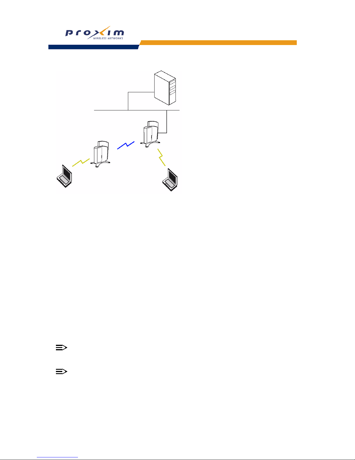
54
Performing Advanced Configuration
Figure 4-9 WDS Example
Bridging WDS
Each WDS link is mapped to a logical WDS port on the AP. WDS ports behave like Ethernet ports rather than like
standard wireless interfaces: on a BSS port, an Access Point learns by association and from frames; on a WDS or
Ethernet port, an Access Point learns from frames only. When setting up a WDS, keep in mind the following:
• The WDS link shares the communication bandwidth with the clients. Therefore, while the maximum data rate for
the Access Point’s cell is still 11 Mb, client throughput will decrease when the WDS link is active.
• If there is no partner MAC address configured in the WDS table, the WDS port remains disabled.
• Each WDS port on a single AP should have a unique partner MAC address. Do not enter the same MAC address
twice in an AP’s WDS port list.
• Each Access Point that is a member of the WDS must have the same Channel setting to communicate with each
other.
• Each Access Point that is a member of the WDS must have the same network domain.
• Each Access Point that is a member of the WDS must have the same WEP Encryption settings. WDS does not
use 802.1x. Therefore, if you want to encrypt the WDS link, you must configure each Access Point to use WEP
encryption, and each Access Point must have the same Encryption Key(s). See
SSID/VLAN/Security.
• If your network does not support spanning tree, be careful to avoid creating network loops between APs. For
example, creating a WDS link between two Access Points connected to the same Ethernet network will create a
network loop (if spanning tree is disabled). For more information, refer to the
Spanning Tree section.
WDS Setup Procedure
NOTE
You must disable Auto Channel Select to create a WDS. Each Access Point that is a member of the WDS
must have the same Channel setting to communicate with each other.
NOTE
For radio cards that belong to the ETSI regulatory domain, ACS is enabled by default, and cannot be disabled.
Therefore, it is not possible to set up a WDS link. This only applies to ETSI 802.11a wireless radios.
To setup a wireless backbone follow the steps below for each AP that you wish to include in the Wireless Distribution
System.
1. Confirm that Auto Channel Select is disabled.
AP 1
AP 2
Client 1
Client 2
Page 57
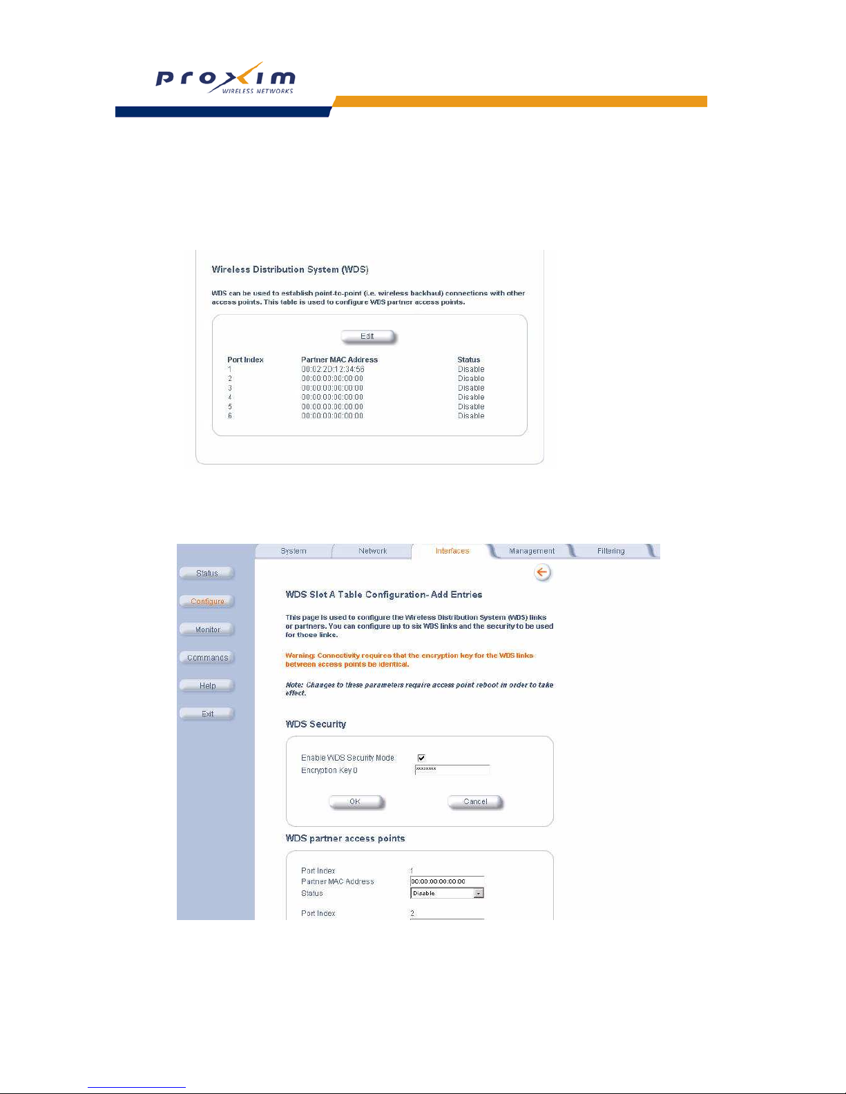
55
Performing Advanced Configuration
2. Write down the MAC Address of the radio that you wish to include in the Wireless Distribution System.
3. Click on Interfaces > Wireless.
4. Scroll down to the Wireless Distribution System heading.
5. Click the Edit button to update the Wireless Distribution System (WDS) Table (see
Figure 4-8).
Figure 4-10 WDS Edit Entry Screen
The WDS Configuration screen will be displayed (see Figure 4-9).
Figure 4-11 WDS Configuration Screen
6. If desired, enable security by checking the Enable WDS Security Mode box.
7. If security mode is enabled, enter a value for Encryption Key 0.
Page 58

56
Performing Advanced Configuration
8. Click OK.
9. Enter the MAC Address that you wrote down in Step 2 in one of the Partner MAC Address field of the Wireless
Distribution Setup window.
10. Set the Status of the device to Enable.
11. Click OK.
12. Reboot the AP.
Ethernet
Select the desired speed and transmission mode from the drop-down menu. Half-duplex means that only one side can
transmit at a time and full-duplex allows both sides to transmit. When set to auto-duplex, the AP negotiates with its
switch or hub to automatically select the highest throughput option supported by both sides.
For best results, Proxim recommends that you configure the Ethernet setting to match the speed and transmission
mode of the device the Access Point is connected to (such as a hub or switch). If in doubt, leave this setting at its
default, auto-speed-auto-duplex. Choose between:
• 10 Mbit/s - half duplex, full duplex, or auto duplex
• 100 Mbit/s - half duplex or full duplex
• auto speed - half duplex or auto duplex
Page 59

57
Performing Advanced Configuration
Management
The Management tab contains five sub-tabs.
– Passwords
– IP Access Table
– Services
– Automatic Configuration (AutoConfig)
– Hardware Configuration Reset (CHRP)
Passwords
The following passwords are configurable:
• SNMP Read Community Password: The password for read access to the AP using SNMP. Enter a password in
both the Password field and the Confirm field. This password must be between 6 and 32 characters. The default
password is “public”.
• SNMP Read/Write Community Password: The password for read and write access to the AP using SNMP. Enter
a password in both the Password field and the Confirm field. This password must be between 6 and 32
characters. The default password is “public”.
• SNMPv3 Authentication Password: The password used when sending authenticated SNMPv3 messages. Enter
a password in both the Password field and the Confirm field. This password must be between 6 and 32
characters, but a length of at least at least 8 characters is recommended. The default password is “public”. Secure
Management (Services tab) must be enabled to configure SNMPv3.
The default SNMPv3 username is administrator, with SHA authentication, and DES privacy protocol.
• SNMPv3 Privacy Password: The password used when sending encrypted SNMPv3 data. Enter a password in
both the Password field and the Confirm field. This password must be between 6 and 32 characters, but a length
of at least at least 8 characters is recommended. The default password is “public”. Secure Management (Services
tab) must be enabled to configure SNMPv3.
• Telnet (CLI) Password: The password for the CLI interface (via serial or Telnet). Enter a password in both the
Password field and the Confirm field. This password must be between 6 and 32 characters. The default password
is “public”.
• HTTP (Web) Password: The password for the Web browser HTTP interface. Enter a password in both the
Password field and the Confirm field. This password must be between 6 and 32 characters. The default password
is “public”.
NOTE
For security purposes Proxim recommends changing ALL PASSWORDS from the default “public”
immediately, to restrict access to your network devices to authorized personnel. If you lose or forget your
password settings, you can always perform the
Reset to Factory Default Procedure.
IP Access Table
The Management IP Access table limits in-band management access to the IP addresses or range of IP addresses
specified in the table. This feature applies to all management options (SNMP, HTTP, and CLI) except for CLI
management over the serial port. To configure this table, click Add and set the following parameters:
• IP Address: Enter the IP Address for the management station.
• IP Mask: Enter a mask that will act as a filter to limit access to a range of IP Addresses based on the IP Address
you already entered.
– The IP mask 255.255.255.255 would authorize the single station defined by the IP Address to configure the
Access Point. The AP would ignore commands from any other IP address. In contrast, the IP mask
255.255.255.0 would allow any device that shares the first three octets of the IP address to configure the AP.
For example, if you enter an IP address of 10.20.30.1 with a 255.255.255.0 subnet mask, any IP address
between 10.20.30.1 and 10.20.30.254 will have access to the AP’s management interfaces.
• Comment: Enter an optional comment, such as the station name.
To edit or delete an entry, click Edit. Edit the information, or select Enable, Disable, or Delete from the Status
pull-down menu.
Page 60

58
Performing Advanced Configuration
Services
You can configure the following management services:
NOTE
You must reboot the Access Point if you change the HTTP Port or Telnet Port.
Secure Management
Secure Management allows the use of encrypted and authenticated communication protocols such as SNMPv3, and
Secure Socket Link (SSL), to manage the Access Point.
• Secure Management Status: Enables the further configuration of HTTPS Access, and SNMPv3. After enabling
Secure Management, you can choose to configure HTTPS (SSL) access on the Services tab, and configure
SNMPv3 passwords on the Passwords tab.
SNMP Settings
• SNMP Interface Bitmask: Configure the interface or interfaces (Ethernet, Wireless, All Interfaces) from which
you will manage the AP via SNMP. Select Disabled to prevent a user from accessing the AP via SNMP.
HTTP Access
• HTTP Interface Bitmap: Configure the interface or interfaces (Ethernet, Wireless, All Interfaces) from which you
will manage the AP via the Web interface. For example, to allow Web configuration via the Ethernet network only,
set HTTP Interface Bitmask to Ethernet. Select Disabled to prevent a user from accessing the AP from the Web
interface.
• HTTP Port: Configure the HTTP port from which you will manage the AP via the Web interface. By default, the
HTTP port is 80. You must reboot the Access Point if you change the HTTP Port.
• HTTP Setup Wizard: The Setup Wizard appears automatically the first time you access the HTTP interface. If you
exited out of the Setup Wizard and want to relaunch it, enable this option, click OK, and then close your browser or
reboot the AP. The Setup Wizard will appear the next time you access the HTTP interface.
HTTPS Access
• HTTPS (Secure Web Status): The user can access the AP in a secure fashion using Secure Socket Layer (SSL)
over port 443. The AP comes pre-installed with all required SSL files: default certificate and private key installed.
Check this box to enable SSL on the AP.
• SSL Certificate Passphrase: After enabling SSL, the only configurable parameter is the SSL passphrase. The
default SSL passphrase is proxim.
The AP supports SSLv3 with a 128-bit encryption certificate maintained by the AP for secure communications
between the AP and the HTTP client. All communications are encrypted using the server and the client-side
certificate.
If you decide to upload a new certificate and private key (using TFTP or HTTP File Transfer), you need to change
the SSL Certificate Passphrase for the new SSL files.
NOTE
SSL requires Internet Explorer version 6, 128 bit encryption, Service Pack 1, and patch Q323308.
NOTE
You need to reboot the AP after enabling or disabling SSL for the changes to take effect.
Accessing the AP through the HTTPS interface
• The user should use a SSL intelligent browser to access the AP through the HTTPS interface. After configuring
SSL, access the AP using https:// followed by the AP’s management IP address.
Page 61
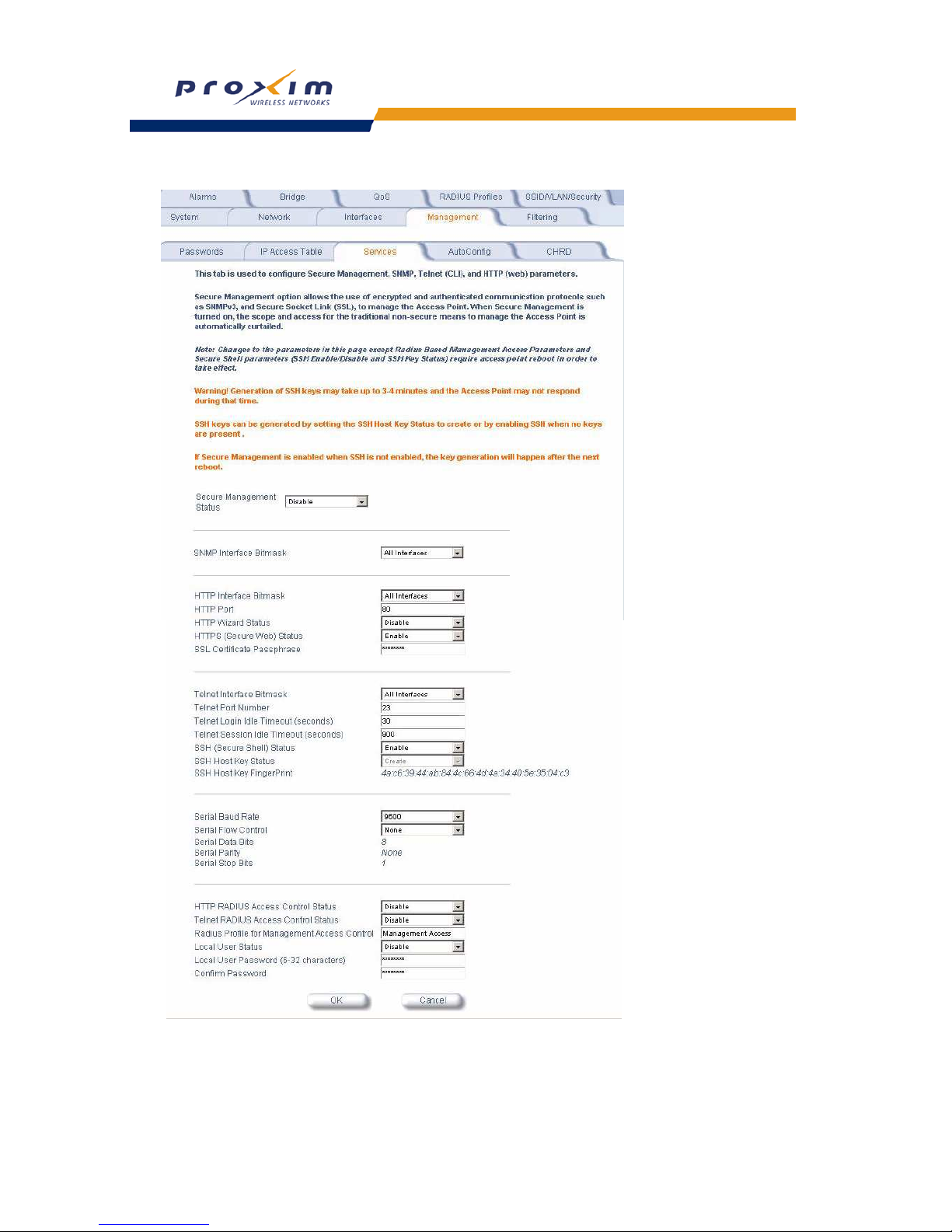
59
Performing Advanced Configuration
Figure 4-12 Management Services Configuration Screen
Page 62

60
Performing Advanced Configuration
Telnet Configuration Settings
• Telnet Interface Bitmask: Select the interface (Ethernet, Wireless, All Interfaces) from which you can manage
the AP via telnet. This parameter can also be used to Disable telnet management.
• Telnet Port: The default port number for Telnet applications is 23. However, you can use this field if you want to
change the Telnet port for security reasons (but your Telnet application also must support the new port number you
select). You must reboot the Access Point if you change the Telnet Port.
• Login Idle Timeout (seconds): Enter the number of seconds the system will wait for a login attempt. The AP
terminates the session when it times out. The range is 1 to 300 seconds; the default is 30 seconds.
• Session Idle Timeout (seconds): Enter the number of seconds the system will wait during a session while there
is no activity. The AP will terminate the session on timeout. The range is 1 to 36000 seconds; the default is 900
seconds.
Secure Shell (SSH) Settings
The AP supports SSH version 2, for secure remote CLI (Telnet) sessions. SSH provides strong authentication and
encryption of session data.
The SSH server (AP) has host keys - a pair of assymetric keys - a private key that resides on the AP and a public
key that is distributed to clients that need to connect to the AP. As the client has knowledge of the server host keys,
the client can verify that it is communicating with the correct SSH server. The client authentication can be performed in
two ways:
• Using asymmetric keys. This method requires all the client keys to be installed on the AP.
• Using a username/password pair to authenticate the user over a secure channel created using SSH.
SSH Session Setup
An SSH session is setup through the following process:
• The SSH server public key is transferred to the client using out-of-band or in-band mechanisms.
• The SSH client verifies the correctness of the server using the server’s public key.
• The user/client authenticates to the server.
• An encrypted data session starts. The maximum number of SSH sessions is limited to two. If there is no activity for
a specified amount of time (the Telnet Session Timeout parameter), the AP will timeout the connection.
SSH Clients
The following SSH clients have been verified to interoperate with the AP’s server. The following table lists the clients,
version number, and the website of the client.
For key generation, OpenSSH client has been verified.
Configuring SSH
Perform the following procedure to enable or disable SSH and set the SSH host key:
1. Click Configure -> Management -> Services.
2. To enable SSH, select “Enable” from the Enable SSH (Secure Shell) drop down menu.
NOTE
When Secure Management is enabled on the AP, SSH will be enabled by default and cannot be disabled.
3. Select the SSH Host Key Status from the drop-down menu.
Host keys must either be generated externally and uploaded to the AP (see Uploading Externally Generated Host
Keys
), generated manually, or auto-generated at the time of SSH initialization if SSH is enabled and no host keys are
present. There is no key present in an AP that is in a factory default state.
Clients Version Website
OpenSSH V3.4-2 http://www.openssh.com
Putty Rel 0.53b http://www.chiark.greenend.org.uk
Zoc 5.00 http://www.emtec.com
Axessh V2.5 http://www.labf.com
Page 63
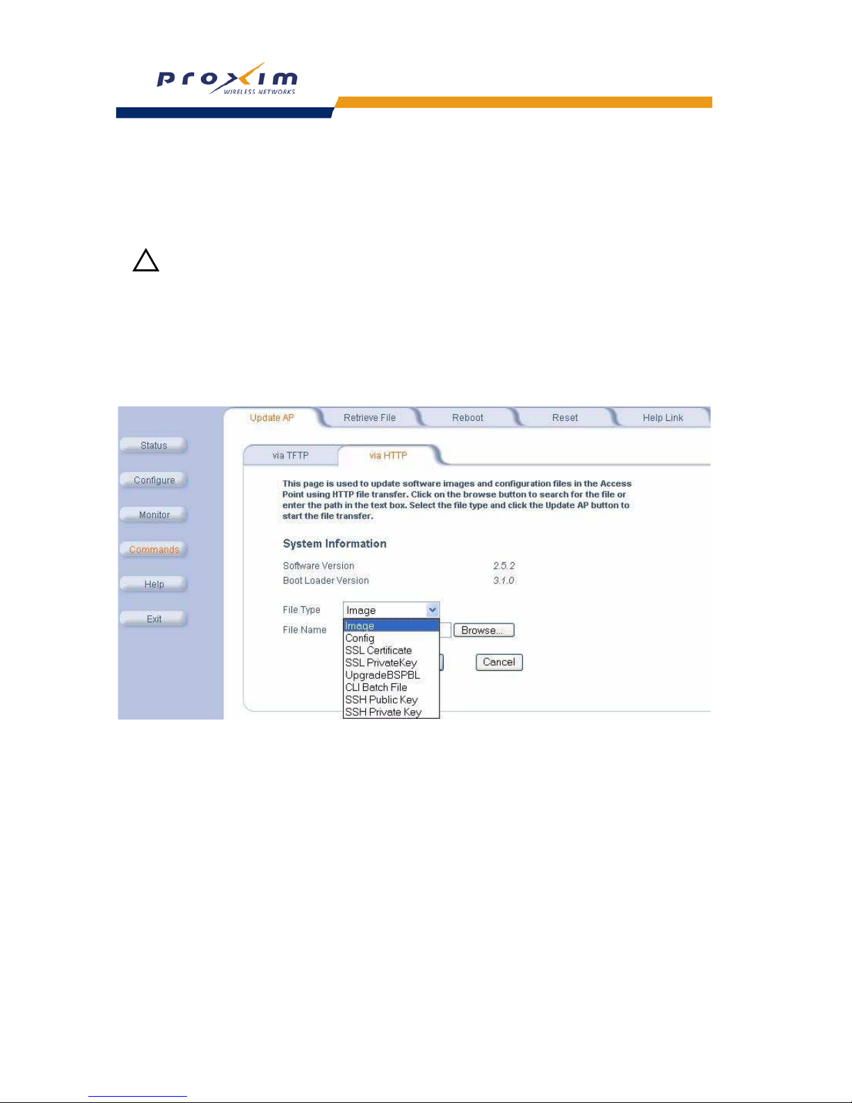
61
Performing Advanced Configuration
To manually generate or delete host keys on the AP:
• Select Create to generate a new pair of host keys.
• Select Delete to remove the host keys from the AP. If no host keys are present, the AP will not allows connections
using SSH. When host keys are created or deleted, the AP updates the fingerprint information displayed on the
Management -> Services page.
WARNING
!
SSH Host key creation may take 3 to 4 minutes during which time the AP may not respond.
Uploading Externally Generated Host Keys
Perform the following procedure to upload externally generated host keys to the AP. You must upload both the SSH
public key and SSH private key for SSH to work.
1. Verify that the host keys have been externally generated. The OpenSSH client has been verify to interoperate with
AP’s SSH server.
2. Click Commands -> Update AP -> via HTTP (or via TFTP).
Figure 4-13 Uploading an Externally Generated SSH Public Key and SSH Private Key
3. Select “SSH Public Key” from the File Type drop-down menu.
4. Click Browse, select the SSH Public Key file on your local machine.
5. Click Open.
6. to initiate the file transfer, click the Update AP button.
7. Select “SSH Private Key” from the File Type drop-down menu.
8. Click Browse, select the SSH Private Key on your local machine.
9. Click Open.
10. To initiate the file transfer, click the Update AP button.
The fingerprint of the new SSH public key will be displayed in the Management -> Services page.
Page 64

62
Performing Advanced Configuration
Serial Configuration Settings
The serial port interface on the AP is enabled at all times. See Setting IP Address using Serial Port for information on
how to access the CLI interface via the serial port. You can configure and view following parameters:
– Serial Baud Rate: Select the serial port speed (bits per second). Choose between 2400, 4800, 9600, 19200,
38400, or 57600; the default Baud Rate is 9600.
– Serial Flow Control: Select either None (default) or Xon/Xoff (software controlled) data flow control.
NOTE
To avoid potential problems when communicating with the AP through the serial port, Proxim recommends
that you leave the Flow Control setting at None (the default value).
• Serial Data Bits: This is a read-only field and displays the number of data bits used in serial communication
(8 data bits by default).
• Serial Parity: This is a read-only field and displays the number of parity bits used in serial communication
(no parity bits by default).
• Serial Stop Bits: This is a read-only field that displays the number of stop bits used in serial communication
(1 stop bit by default).
NOTE
The serial port bit configuration is commonly referred to as 8N1.
RADIUS Based Management Access
User management of APs can be centralized by using a RADIUS server to store user credentials. The AP
cross-checks credentials using RADIUS protocol and the RADIUS server accepts or rejects the user.
HTTP/HTTPS and Telnet/SSH users can be managed with RADIUS. Serial CLI and SNMP cannot be managed by
RADIUS. Two types of users can be supported using centralized RADIUS management:
• Super User: The super user has access to all functionality of a management interface. A super user is configured
in the RADIUS server by setting the filter ID attribute (returned in the RADIUS Accept packet) for the user to a
value of “super user” (not case sensitive). A user is considered a super user if the value of the filter-id attribute
returned in the RADIUS Accept packet for the user is “super user” (not case sensitive).
• Limited User: A limited user has access to only a limited set of functionality on a management interface. All users
who are not super users are considered limited users. However, a limited user is configured in the RADIUS server
by setting the filter-id attribute (returned in the RADIUS Accept packet) to “limited user” (not case sensitive).
Limited users do not have access to the following configuration capabilities:
– Update/retrieve files to and from APs
– Reset the AP to factory defaults
– Reboot the AP
– Change management properties related to RADIUS, management modes, and management passwords.
When RADIUS Based Management is enabled, a local user can be configured to provide Telnet, SSH, and HTTP(S)
access to the AP when RADIUS servers fail. The local user has super user capabilities. When secure management is
enabled, the local user can only login using secure means (i.e., SSH or SSL). When the local user option is disabled
the only access to the AP when RADIUS servers are down will be through serial CLI or SNMP.
The Radius Based Management Access parameters allows you to enable HTTP or Telnet Radius Management
Access, to configure a RADIUS Profile for management access control, and to enable or disable local user access,
and configure the local user password. You can configure and view the following parameters:
• HTTP RADIUS Access Control Status: Enable RADIUS management of HTTP/HTTPS users.
• Telnet RADIUS Access Control Status: Enable RADIUS management of Telnet/SSH users.
• RADIUS Profile for Management Access Control: Specifies the RADIUS Profile to be used for RADIUS Based
Management Access.
• Local User Status: Enables or disables the local user when RADIUS Based Management is enabled. The default
local user ID is root.
• Local User Password and Confirm Password: The default local user password is public. “Root” cannot be
configured as a valid user for Radius based management access when local user access is enabled.
Page 65

63
Performing Advanced Configuration
Automatic Configuration (AutoConfig)
The Automatic Configuration feature which allows an AP to be automatically configured by downloading a specific
configuration file from a TFTP server during the boot up process.
Automatic Configuration is disabled by default. The configuration process for Automatic Configuration varies
depending on whether the AP is configured for dynamic or static IP.
When an AP is configured for dynamic IP, the Configuration filename and the TFTP server IP address are contained in
the DHCP response when the AP gets its IP address dynamically from the DHCP server. When configured for static IP,
these parameters are instead configured in the AP interface.
After setting up automatic configuration you must reboot the AP. When the AP reboots it receives the new
configuration information and must reboot one additional time. If Syslog is configured, a Syslog message will appear
indicating the success or failure of the Automatic Configuration.
Auto Configuration and the CLI Batch File
The Auto Configuration feature allows download of the TLV (tag, length, value) format configuration file or the CLI
Batch file. The AP detects whether the file uploaded is TLV format or a CLI Batch file. If the AP detects a CLI Batch file
(a file with extension .cli), the AP executes the file immediately.
The AP will reboot after executing the CLI Batch file. Auto Configuration will not result in repeated reboots if the CLI
Batch file contains rebootable parameters.
For more information, refer to
CLI Batch File.
Set up Automatic Configuration for Static IP
Perform the following procedure to enable and set up Automatic Configuration when you have a static IP address for
the TFTP server.
1. Click Configure > Management > AutoConfig.
The Automatic Configuration Screen appears.
2. Check Enable Auto Configuration.
3. Enter the Configuration Filename.
4. Enter the IP address of the TFTP server in the TFTP Server Address field.
NOTE
The default filename is “config”. The default TFTP IP address is “169.254.128.133” for AP-600.
5. Click OK to save the changes.
6. Reboot the AP. When the AP reboots it receives the new configuration information and must reboot one additional
time. If a Syslog server was configured, the following messages can be observed on the Syslog server:
• AutoConfig for Static IP
• TFTP server address and configuration filename
• AutoConfig Successful
Page 66
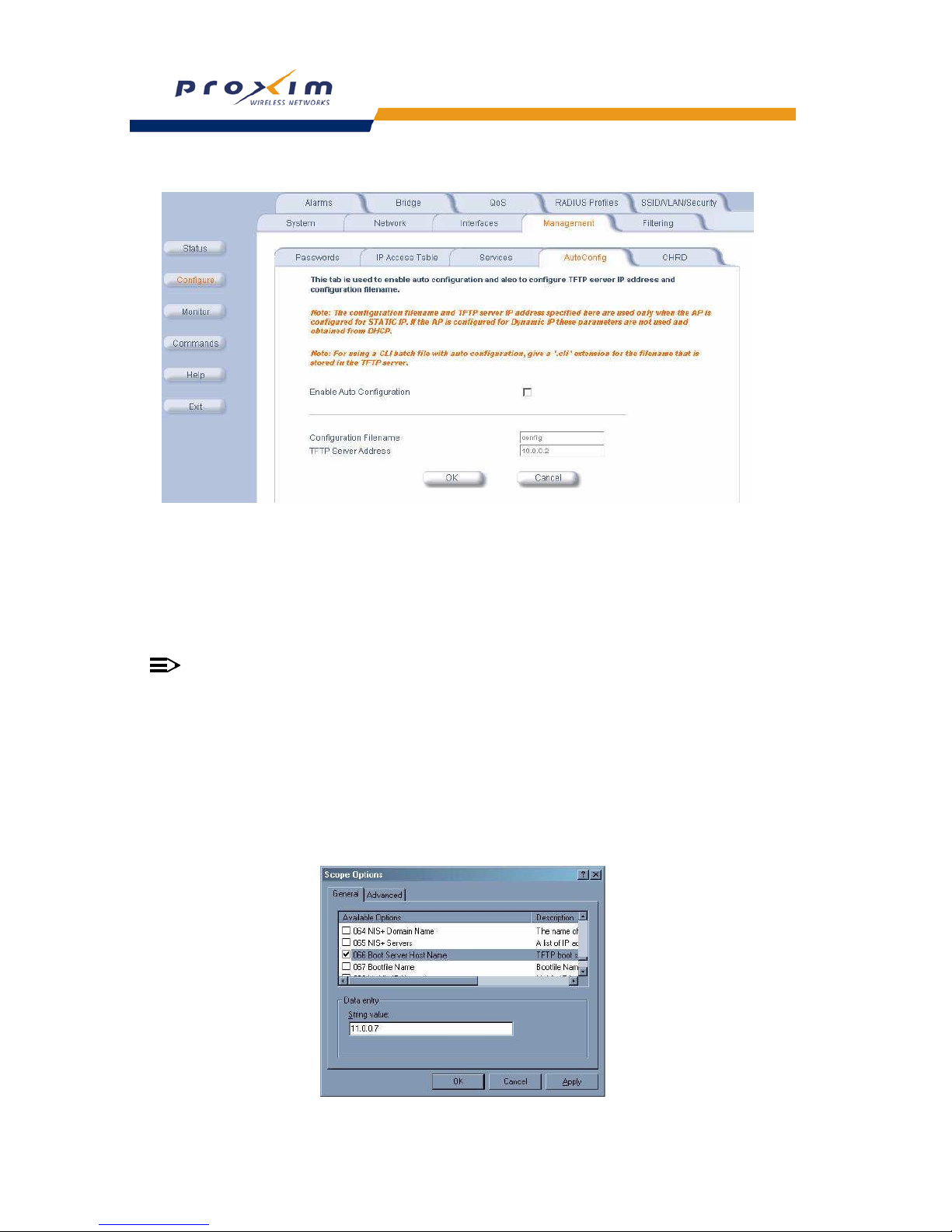
64
Performing Advanced Configuration
Figure 4-14 Automatic Configuration Screen
Set up Automatic Configuration for Dynamic IP
Perform the following procedure to enable and set up Automatic Configuration when you have a dynamic IP address
for the TFTP server via DHCP.
The Configuration filename and the TFTP server IP address are contained in the DHCP response when the AP gets its
IP address dynamically from the DHCP server. A Syslog server address is also contained in the DHCP response,
allowing the AP to send Auto Configuration success and failure messages to a Syslog server.
NOTE
The configuration filename and TFTP server IP address are configured only when the AP is configured for
Static IP. If the AP is configured for Dynamic IP these parameters are not used and obtained from DHCP.
1. Click Configure > Management > AutoConfig.
The Automatic Configuration Screen appears.
2. Check Enable Auto Configuration.
When the AP is Configured with Dynamic IP, the DHCP server should be configured with the TFTP Server IP address
("Boot Server Host Name", option 66) and Configuration file ("Bootfile name", option 67) as follows (note that this
example uses a Windows 2000 server):
3. Select DHCP Server > DHCP Option > Scope.
The DHCP Options: Scope Screen appears.
Page 67
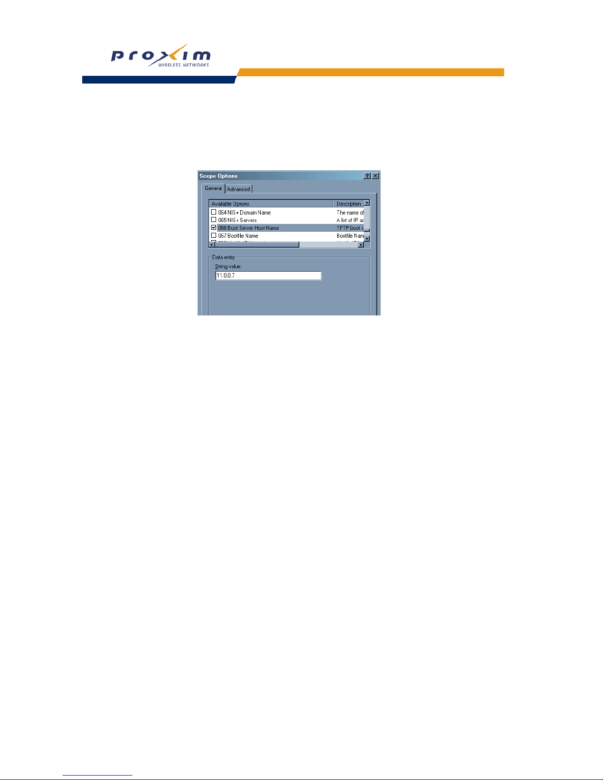
65
Performing Advanced Configuration
Figure 4-15 DHCP Options: Setting the Boot Server Host Name
4. Add the Boot Server Host Name and Boot Filename parameters to the Active Options list.
5. Set the value of the Boot Server Host Name Parameter to the host name or IP Address of the TFTP server. For
example: 11.0.0.7.
Figure 4-16 DHCP Options: Setting the Boot Server Host Name
6. Set the value of the Bootfile Name parameter to the Configuration filename. For example: AP-Config
7. If using Syslog, set the Log server IP address (option 7, Log Servers).
8. Reboot the AP. When the AP reboots it receives the new configuration information and must reboot one additional
time. If a Syslog server was configured, the following messages can be observed on the Syslog server:
• AutoConfig for Dynamic IP
• TFTP server address and configuration filename
• AutoConfig Successful
Page 68

66
Performing Advanced Configuration
Hardware Configuration Reset (CHRP)
Hardware Configuration Reset Status is a parameter that defines the hardware configuration reset behavior of the AP
(i.e., what effect pressing the reload button has on an AP operating in normal operating mode).
If a user loses or forgets the AP’s HTTP/Telnet/SNMP password, the reset button on the AP provides a way to reset
the AP to default configuration values to gain access to the AP. However, in AP deployments where physical access to
the AP is not protected, an unauthorized person could reset the AP to factory defaults and thus gain control of the AP.
The user can disable the hardware configuration reset functionality to prevent unauthorized access.
The hardware configuration reset feature operates as follows:
• When hardware configuration reset is enabled, the user can press the hardware reload button for 10 seconds
when the AP is in normal operational mode in order to delete the AP configuration.
• When hardware configuration reset is disabled, pressing the reload button when the AP is in normal operational
mode does not have any effect on the AP.
• The hardware configuration reset parameter does not have any effect on the functionality of the reload button to
delete the AP image during AP boot loaded execution.
• The default hardware configuration reset status is enabled. When disabling hardware configuration reset, the user
is recommended to configure a configuration reset password. A configuration reset option appears on the serial
port during boot up, before the AP reads its configuration and initializes.
• Whenever the AP is reset to factory default configuration, hardware configuration reset status is enabled and the
configuration reset password is set to the default, “public”.
• If secure mode is enabled in the AP, only secure (SSL, SNMPv3, SSH) users can modify the values of the
Hardware Configuration Reset Status and the configuration reset password.
Configuration Reset via Serial Port During Bootup
If hardware configuration reset is disabled, the user gets prompted by a configuration reset option to reset the AP to
factory defaults during boot up from the serial interface. By pressing a key sequence (ctrl-R), the user gets prompted to
enter a configuration reset password before the configuration is reset.
NOTE
It is important to safely store the configuration reset password. If a user forgets the configuration reset
password, the user will be unable to reset the AP to factory default configuration if the AP becomes
inaccessible and the hardware configuration reset functionality is disabled.
Page 69
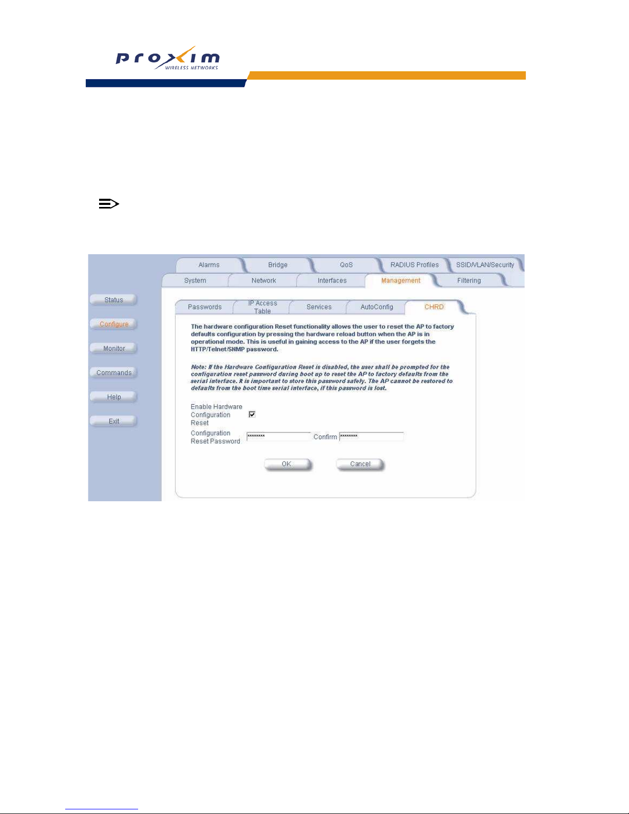
67
Performing Advanced Configuration
Configuring Hardware Configuration Reset
Perform the following procedure to configure Hardware Configuration Reset and to set the Configuration Reset
Password.
1. Click Configure -> Management -> CHRD.
2. Check (enable) or uncheck (disable) the Enable Hardware Configuration Reset checkbox.
3. Change the default Configuration Reset Password in the “Configuration Reset Password” and “Confirm” fields.
NOTE
It is important to safely store the configuration reset password. If a user forgets the configuration reset
password, the user will be unable to reset the AP to factory default configuration if the AP becomes
inaccessible and the hardware configuration reset functionality is disabled.
Figure 4-17 Hardware Configuration Reset
Procedure to Reset Configuration via the Serial Interface
1. During boot up, observe the message output on the serial interface.
The AP prompts the user with the message: “Press ctrl-R in 3 seconds to choose configuration reset option.”
2. Enter ctrl-R within 3 seconds after being prompted.
The AP prompts the user with “Press ctrl-Z to continue with normal boot up or enter password to reset configuration.” If
the user enters ctrl-Z, the AP continues to boot with the stored configuration.
3. Enter the configuration reset password. The default configuration reset password is “public”.
When the correct configuration reset password is entered, the AP gets reset to factory defaults and displays the
message “AP has been reset to Factory Default Settings.” The AP continues to boot up. If an incorrect configuration
reset password is entered, the AP shows an error message and reprompts the user. If the incorrect password is
entered three times in a row, the AP proceeds to boot up.
Page 70

68
Performing Advanced Configuration
Filtering
The Access Point’s Packet Filtering features help control the amount of traffic exchanged between the wired and
wireless networks. There are four sub-tabs under the Filtering tab:
– Ethernet Protocol
– Static MAC
– Advanced
– TCP/UDP Port
Ethernet Protocol
The Ethernet Protocol Filter blocks or forwards packets based on the Ethernet protocols they support.
Follow these steps to configure the Ethernet Protocol Filter:
1. Select the interface or interfaces that will implement the filter from the Ethernet Protocol Filtering drop-down
menu.
• Ethernet: Packets are examined at the Ethernet interface
• Wireless: Packets are examined at the Wireless A interface
• All Interfaces: Packets are examined at both interfaces
• Disabled: The filter is not used
2. Select the Filter Operation Type.
• If set to Passthru, only the enabled Ethernet Protocols listed in the Filter Table will pass through the bridge.
• If set to Block, the bridge will block enabled Ethernet Protocols listed in the Filter Table.
3. Configure the Ethernet Protocol Filter Table. This table is pre-populated with existing Ethernet Protocol Filters,
however, you may enter additional filters by specifying the appropriate parameters.
• To add an entry, click Add, and then specify the Protocol Number and a Protocol Name.
— Protocol Number: Enter the protocol number. See
http://www.iana.org/assignments/ethernet-numbers
for a list of protocol numbers.
— Protocol Name: Enter related information, typically the protocol name.
• To edit or delete an entry, click Edit and change the information, or select Enable, Disable, or Delete from the
Status drop-down menu.
• An entry’s status must be enabled in order for the protocol to be subject to the filter.
4. Reboot the AP for any changes to the Ethernet Protocol Filter Table to take effect.
Static MAC
The Static MAC Address filter optimizes the performance of a wireless (and wired) network. When this feature is
properly configured, the AP can block traffic between wired devices and wireless devices based on MAC address.
For example, you can set up a Static MAC filter to prevent wireless clients from communicating with a specific server
on the Ethernet network. You can also use this filter to block unnecessary multicast packets from being forwarded to
the wireless network.
NOTE
The Static MAC Filter is an advanced feature. You may find it easier to control wireless traffic via other filtering
options, such as Ethernet Protocol Filtering.
Each static MAC entry contains the following fields:
• Wired MAC Address
• Wired Mask
• Wireless MAC Address
• Wireless Mask
• Comment: This field is optional.
• Status
Each MAC Address or Mask is comprised of 12 hexadecimal digits (0-9, A-F) that correspond to a 48-bit identifier.
(Each hexadecimal digit represents 4 bits (0 or 1).)
Page 71
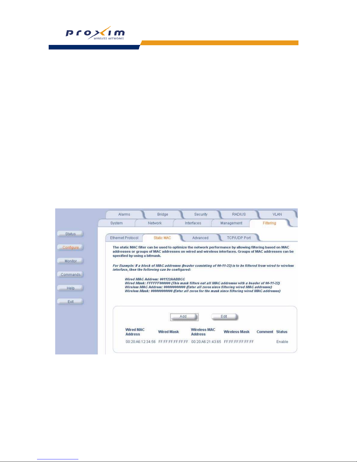
69
Performing Advanced Configuration
Taken together, a MAC Address/Mask pair specifies an address or a range of MAC addresses that the AP will look for
when examining packets. The AP uses Boolean logic to perform an “AND” operation between the MAC Address and
the Mask at the bit level. However, for most users, you do not need to think in terms of bits. It should be sufficient to
create a filter using only the hexadecimal digits 0 and F in the Mask (where 0 is any value and F is the value specified
in the MAC address). A Mask of 00:00:00:00:00:00 corresponds to all MAC addresses, and a Mask of
FF:FF:FF:FF:FF:FF applies only to the specified MAC Address.
For example, if the MAC Address is 00:20:A6:12:54:C3 and the Mask is FF:FF:FF:00:00:00, the AP will examine the
source and destination addresses of each packet looking for any MAC address starting with 00:20:A6. If the Mask is
FF:FF:FF:FF:FF:FF, the AP will only look for the specific MAC address (in this case, 00:20:A6:12:54:C3).
When creating a filter, you can configure the Wired parameters only, the Wireless parameters only, or both sets of
parameters. Which parameters to configure depends upon the traffic that you want block:
– To prevent all traffic from a specific wired MAC address from being forwarded to the wireless network, configure
only the Wired MAC Address and Wired Mask (leave the Wireless MAC Address and Wireless Mask set to all
zeros).
– To prevent all traffic from a specific wireless MAC address from being forwarded to the wired network, configure
only the Wireless MAC address and Wireless Mask (leave the Wired MAC Address and Wired Mask set to all
zeros).
– To block traffic between a specific wired MAC address and a specific wireless MAC address, configure all four
parameters.
To create an entry, click Add and enter the appropriate MAC addresses and Masks to setup a filter. The entry is
enabled automatically when saved. To edit an entry, click Edit. To disable or remove an entry, click Edit and change
the Status field from Enable to Disable or Delete.
Figure 4-18 Static MAC Configuration Screen
Page 72

70
Performing Advanced Configuration
Static MAC Filter Examples
Consider a network that contains a wired server and three wireless clients. The MAC address for each unit is as
follows:
– Wired Server: 00:40:F4:1C:DB:6A
– Wireless Client 1: 00:02:2D:51:94:E4
– Wireless Client 2: 00:02:2D:51:32:12
– Wireless Client 3: 00:20:A6:12:4E:38
Prevent Two Specific Devices from Communicating
Configure the following settings to prevent the Wired Server and Wireless Client 1 from communicating:
• Wired MAC Address: 00:40:F4:1C:DB:6A
• Wired Mask: FF:FF:FF:FF:FF:FF
• Wireless MAC Address: 00:02:2D:51:94:E4
• Wireless Mask: FF:FF:FF:FF:FF:FF
Result: Traffic between the Wired Server and Wireless Client 1 is blocked. Wireless Clients 2 and 3 can still
communicate with the Wired Server.
Prevent Multiple Wireless Devices From Communicating With a Single Wired Device
Configure the following settings to prevent Wireless Clients 1 and 2 from communicating with the Wired Server.
• Wired MAC Address: 00:40:F4:1C:DB:6A
• Wired Mask: FF:FF:FF:FF:FF:FF
• Wireless MAC Address: 00:02:2D:51:94:E4
• Wireless Mask: FF:FF:FF:00:00:00
Result: When a logical “AND” is performed on the Wireless MAC Address and Wireless Mask, the result corresponds
to any MAC address beginning with the 00:20:2D prefix. Since Wireless Client 1 and Wireless Client 2 share the same
prefix (00:02:2D), traffic between the Wired Server and Wireless Clients 1 and 2 is blocked. Wireless Client 3 can still
communicate with the Wired Server since it has a different prefix (00:20:A6).
Prevent All Wireless Devices From Communicating With a Single Wired Device
Configure the following settings to prevent all three Wireless Clients from communicating with Wired Server 1.
• Wired MAC Address: 00:40:F4:1C:DB:6A
• Wired Mask: FF:FF:FF:FF:FF:FF
• Wireless MAC Address: 00:00:00:00:00:00
• Wireless Mask: 00:00:00:00:00:00
Result: The Access Point blocks all traffic between Wired Server 1 and all wireless clients.
Prevent A Wireless Device From Communicating With the Wired Network
Configure the following settings to prevent Wireless Client 3 from communicating with any device on the Ethernet.
• Wired MAC Address: 00:00:00:00:00:00
• Wired Mask: 00:00:00:00:00:00
• Wireless MAC Address: 00:20:A6:12:4E:38
• Wireless Mask: FF:FF:FF:FF:FF:FF
Result: The Access Point blocks all traffic between Wireless Client 3 and the Ethernet network.
Prevent Messages Destined for a Specific Multicast Group from Being Forwarded to the Wireless LAN
If there are devices on your Ethernet network that use multicast packets to communicate and these packets are not
required by your wireless clients, you can set up a Static MAC filter to preserve wireless bandwidth. For example, if
routers on your network use a specific multicast address (such as 01:00:5E:00:32:4B) to exchange information, you
can set up a filter to prevent these multicast packets from being forwarded to the wireless network:
• Wired MAC Address: 01:00:5E:00:32:4B
Page 73

71
Performing Advanced Configuration
• Wired Mask: FF:FF:FF:FF:FF:FF
• Wireless MAC Address: 00:00:00:00:00:00
• Wireless Mask: 00:00:00:00:00:00
Result: The Access Point does not forward any packets that have a destination address of 01:00:5E:00:32:4B to the
wireless network.
Advanced
You can configure the following advanced filtering options:
• Enable Proxy ARP: Place a check mark in the box provided to allow the Access Point to respond to Address
Resolution Protocol (ARP) requests for wireless clients. When enabled, the AP answers ARP requests for wireless
stations without actually forwarding them to the wireless network. If disabled, the Access Point will bridge ARP
requests for wireless clients to the wireless LAN.
• Enable IP/ARP Filtering: Place a check mark in the box provided to allow IP/ARP filtering based on the IP/ARP
Filtering Address and IP Mask. Leave the box unchecked to prevent filtering. If enabled, you should also configure
the IP/ARP Filtering Address and IP/ARP IP Mask.
• IP/ARP Filtering Address: Enter the Network filtering IP Address.
• IP/ARP IP Mask: Enter the Network Mask IP Address.
The following protocols are listed in the Advanced Filter Table:
• Deny IPX RIP
• Deny IPX SAP
• Deny IPX LSP
• Deny IP Broadcasts
• Deny IP Multicasts
The AP can filter these protocols in the wireless-to-Ethernet direction, the Ethernet-to-wireless direction, or in both
directions. Click Edit and use the Status field to Enable or Disable the filter.
TCP/UDP Port
Port-based filtering enables you to control wireless user access to network services by selectively blocking TCP/UDP
protocols through the AP. A user specifies a Protocol Name, Port Number, Port Type (TCP, UDP, or TCP/UDP), and
filtering interfaces (Only Ethernet, Only Wireless, All Interfaces) in order to block access to services, such as Telnet
and FTP, and traffic, such as NETBIOS and HTTP.
For example, an AP with the following configuration would discard frames received on its Ethernet interface with a
UDP destination port number of 137, effectively blocking NETBIOS Name Service packets.
Adding TCP/UDP Port Filters
1. Place a check mark in the box labeled Enable TCP/UDP Port Filtering.
2. Click Add under the TCP/UDP Port Filter Table heading.
3. In the TCP/UDP Port Filter Table, enter the Protocol Names to filter.
4. Set the destination Port Number (a value between 1 and 65535) to filter. See the IANA Web site at
http://www.iana.org/assignments/port-numbers for a list of assigned port numbers and their descriptions.
5. Set the Port Type for the protocol: TCP, UDP, or both (TCP/UDP).
6. Set the Interface to:
• Only Ethernet
• Only Wireless
Protocol Type
(TCP/UDP)
Destination
Port Number
Protocol Name Interface Status
(Enable/Disable)
UDP 137 NETBIOS
Name Service
Ethernet Enable
Page 74

72
Performing Advanced Configuration
• All Interfaces
7. Click OK.
Editing TCP/UDP Port Filters
1. Click Edit under the TCP/UDP Port Filter Table heading.
2. Make any changes to the Protocol Name or Port Number for a specific entry, if necessary.
3. Modify the Port Type, Interface, and Status using the drop down menus, as appropriate.
4. Select OK
.
Page 75
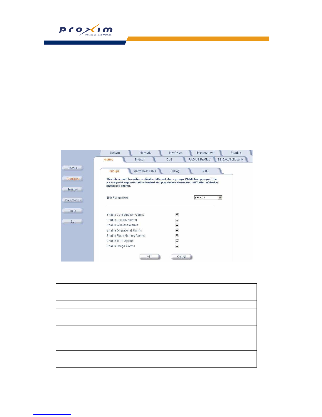
73
Performing Advanced Configuration
Alarms
This tab has three sub-tabs.
– Groups
– Alarm Host Table
– Syslog
– Rogue Access Point Detection (RAD)
Groups
The AP can be configured to generate and send alarms/notifications/traps as version 1 or a version 2c. Use the
drop-down menu to select SNMP alarm type.
There are seven alarm groups that can be enabled or disabled via the Web interface. Place a check mark in the box
provided to enable a specific group. Remove the check mark from the box to disable the alarms. Alarm
Severity Levels
vary.
Figure 4-19 Syslog Configuration Screen
• Configuration Trap Group
Trap Name Description
DNS IP Address not Configured oriTrapDNSIPNotConfigured
RADIUS Authentication not Configured oriTrapRADIUSAuthenticationNotConfigured
RADIUS Accounting not Configured oriTrapRADIUSAccountingNotConfigured
Duplicate IP Address Encountered oriTrapDuplicateIPAddressEncountered
VLAN ID Invalid Configuration oriTrapVLANIDInvalidConfiguration
Auto Configuration Failure oriTrapAutoConfigFailure
CLI Configuration Execution Failure oriTrapBatchExecFailure
CLI Configuration Execution Start oriTrapBatchFileExecStart
CLI Configuration Execution End oriTrapBatchFileExecEnd
Page 76

74
Performing Advanced Configuration
• Security Trap Group
• Wireless Interface/Card Trap Group
• Operational Trap Group
• Flash Memory Trap Group
Trap Name Description
Authentication Failure oriTrapAuthenticationFailure
Unauthorized Manager Detected oriTrapUnauthorizedManagerDetected
RAD Scan Complete oriTrapRADScanComplete
RAD Scan Results oriTrapRADScanResults
Trap Name Description
Wireless Card Not Present oriTrapWLCNotPresent
Wireless Card Failure oriTrapWLCFailure
Wireless Card Removal oriTrapWLCRemoval
Incompatible Firmware oriTrapWLCIncompatibleFirmware
Incompatible Vendor oriTrapWLCIncompatibleVendor
Firmware Download Failure (classic card only) oriTrapWLCFirmwareDownloadFailure
Firmware Failure oriTrapWLCFirmwareFailure
Radar Interference Detected oriTrapWLCRadarInterferenceDetected
Trap Name Description
Unrecoverable Software Error Detected oriTrapUnrecoverableSoftwareErrorDetected
RADIUS Server Not Responding oriTrapRADIUSServerNotResponding
Module Not Initialized oriTrapModuleNotInitialized
Device Rebooting oriTrapDeviceRebooting
Task Suspended oriTrapTaskSuspended
BootP Failed oriTrapBootPFailed
DHCP Client Failed oriTrapDHCPFailed
DNS Client Lookup Failure oriTrapDNSClientLookupFailure
SSL Initialization Failure oriTrapSSLInitializationFailure
SSH Initialization Status oriTrapSSHInitializationStatus
Assigned User VLAN ID oriTrapVLANIDUserAssignment
DHCP Lease Renewal oriTrapDHCPLeaseRenewal
Trap Name Description
Flash Memory Empty oriTrapFlashMemoryEmpty
Page 77

75
Performing Advanced Configuration
• TFTP Trap Group
• Image Trap Group
In addition, the AP supports these standard traps, which are always enabled:
• RFC 1215-Trap
• Bridge MIB (RFC 1493) Alarms
All these alarm groups correspond to System Alarms that are displayed in the System Status screen, including the
traps that are sent by the AP to the SNMP managers specified in the
Alarm Host Table.
Flash Memory Corrupted oriTrapFlashMemoryCorrupted
Restoring Last Known Good Configuration File oriTrapFlashMemoryRestoringLastKnownGoodConfiguration
Trap Name Description
TFTP Operation Failure oriTrapTFTPFailedOperation
TFTP Operation Initiated oriTrapTFTPOperationInitiated
TFTP Operation Completed oriTrapTFTPOperationCompleted
Trap Name Description
Zero Size Image oriTrapZeroSizeImage
Invalid Image oriTrapInvalidImage
Image Too Large oriTrapImageTooLarge
Incompatible Image oriTrapIncompatibleImage
Invalid Image Digital Signature oriTrapInvalidImageDigitalSignature
Trap Name Description
coldStart The AP has been turned on or rebooted.
Trap Severity Level: Informational
linkUp The AP's Ethernet interface link is up (working).
Trap Severity Level: Informational
linkDown The AP's Ethernet interface link is down (not working).
Trap Severity Level: Informational
Trap Name Description
newRoot This trap indicates that the AP has become the new root in the Spanning Tree
network.
Trap Severity Level: Informational
topologyChange This trap is sent by the AP when any of its configured ports transitions from the
Learning state to the Forwarding state, or from the Forwarding state to the
Blocking state.
This trap is not sent if a newRoot trap is sent for the same transition.
Trap Severity Level: Informational
Page 78

76
Performing Advanced Configuration
Severity Levels
There are three severity levels for system alarms:
– Critical
– Major
– Informational
Critical alarms will often result in severe disruption in network activity or an automatic reboot of the AP
Major alarms are usually activated due to a breach in the security of the system. Clients cannot be authenticated or an
attempt at unauthorized access into the AP has been detected.
Informational alarms are there to provide the network administrator with some general information about the activities
the AP is performing.
Alarm Host Table
To add an entry and enable the AP to send SNMP trap messages to a Trap Host, click Add, and then specify the IP
Address and Password for the Trap Host.
NOTE
Up to 10 entries are possible in the Alarm Host table.
• IP Address: Enter the Trap Host IP Address.
• Password: Enter the password in the Password field and the Confirm field.
• Comment: Enter an optional comment, such as the alarm (trap) host station name.
To edit or delete an entry, click Edit. Edit the information, or select Enable, Disable, or Delete from the Status
drop-down menu.
Syslog
The Syslog messaging system enables the AP to transmit event messages to a central server for monitoring and
troubleshooting. The AP can send messages to multiple Syslog servers. The access point logs “Session Start (Log-in)”
and “Session Stop (Log-out)” events for each wireless client as an alternative to RADIUS accounting.
See RFC 3164 at
http://www.rfc-editor.org for more information on the Syslog standard.
Setting Syslog Event Notifications
Syslog Events are logged according to the level of detail specified by the administrator. Logging only urgent system
messages will create a far smaller, more easily read log then a log of every event the system encounters. Determine
which events to log by selecting a priority defined by the following scale:
Configuring Syslog Event Notifications
You can configure the following Syslog settings from the HTTP interface:
• Enable Syslog: Place a check mark in the box provided to enable system logging.
• Syslog Port Number: This field is read-only and displays the port number (514) assigned for system logging.
• Syslog Lowest Priority Logged: The AP will send event messages to the Syslog server that correspond to the
selected priority and above. For example, if set to 6, the AP will transmit event messages labeled priority 0 to 6 to
the Syslog server(s). This parameter supports a range between 1 and 7; 6 is the default.
Event Priority Description
LOG_EMERG 0 system is unusable
LOG_ALERT 1 action must be taken immediately
LOG_CRIT 2 critical conditions
LOG_ERR 3 error conditions
LOG_WARNING 4 warning conditions
LOG_NOTICE 5 normal but significant condition
LOG_INFO 6 informational
LOG_DEBUG 7 debug-level messages
Page 79

77
Performing Advanced Configuration
• Syslog Heartbeat Status: Enables or disables the sending of heartbeat messages from the AP to the configured
Syslog servers.
• Syslog Heartbeat Interval: Specifies the interval (in seconds) at which Syslog Heartbeat messages are sent to
the configured Syslog servers.
• Syslog Host Table: This table specifies the IP addresses of a network servers that the AP will send Syslog
messages to. Click Add to create a new entry. Click Edit to change an existing entry. Each entry contains the
following field:
– IP Address: Enter the IP Address for the management host.
– Comment: Enter an optional comment such as the host name.
– Status: The entry is enabled automatically when saved (so the Status field is only visible when editing an
entry). Disable or delete entries by changing this field’s value.
Syslog Messages
The following messages are supported in the AP:
Message Severity
Auto Configuration via DHCP Informational
Auto Configuration for static IP Informational
TFTP server IP/Config filename missing in DHCP response Minor
AutoConfig TFTP server IP address used is <IP address> Informational
AutoConfig filename used is <filename> Informational
AutoConfig TFTP download failed Minor
Image Error check, invalid image Minor
AP Heartbeat status Minor
Client Authentication State Informational
Accounting Informational
RADIUS Responses Informational
Page 80

78
Performing Advanced Configuration
Rogue Access Point Detection (RAD)
The Rogue AP Detection (RAD) feature provides an additional security level for wireless LAN deployments. Rogue AP
detection provides a mechanism for detecting Rogue Access Points by utilizing the coverage of the trusted Access
Point deployment.
The Rogue AP Scan employs background scanning using low-level 802.11 scanning functions for effective wireless
detection of Access Points in its coverage area with minimal impact on the normal operation of the Access Point.
This RAD feature can be enabled on an Access Point via its HTTP, CLI, or SNMP Interfaces. The scan repetition
duration is configurable. The Access Point will periodically scan the wireless network and report all the available
Access Points within its coverage area using SNMP traps. For additional reliability the results are stored in the Access
Point in a table, which can be queried via SNMP. The BSSID and Channel number of the detected Access Points are
provided in the scan results.
The RAD scan is done on a channel list initialized based on the regulatory domain of the device. The RAD Scan then
performs background scanning on all the channels in this channel list using 802.11 MAC scanning functions. It will
either actively scan the network by sending probe requests or passively scan by only listening for beacons. The access
point information is then gathered from the probe responses and beacons.
To minimize traffic disruption and maximize the scanning efficiency, the RAD feature employs an enhanced
background-scanning algorithm and uses the CTS to Self mechanism to keep the clients silent. The scanning
algorithm allows traffic to be serviced between each channel scan. Before start of every scan (except scan on the
working channel) the CTS to self-mechanism is used to set the NAV values of clients to keep them silent during the
scanning period. In addition, the scan repetition duration can also be configured to reduce the frequency of RAD scan
cycles to maximize Access Point performance.
RAD Configuration Requirements
The RAD feature can be configured/monitored via the HTTP, CLI, or SNMP management interfaces.
The following management options are provided:
• The RAD feature can be enabled or disabled.
• The repetition interval of RAD can be configured.
• SNMP Traps are sent after completion of a RAD scan cycle and also whenever a new Access Point is detected.
Page 81
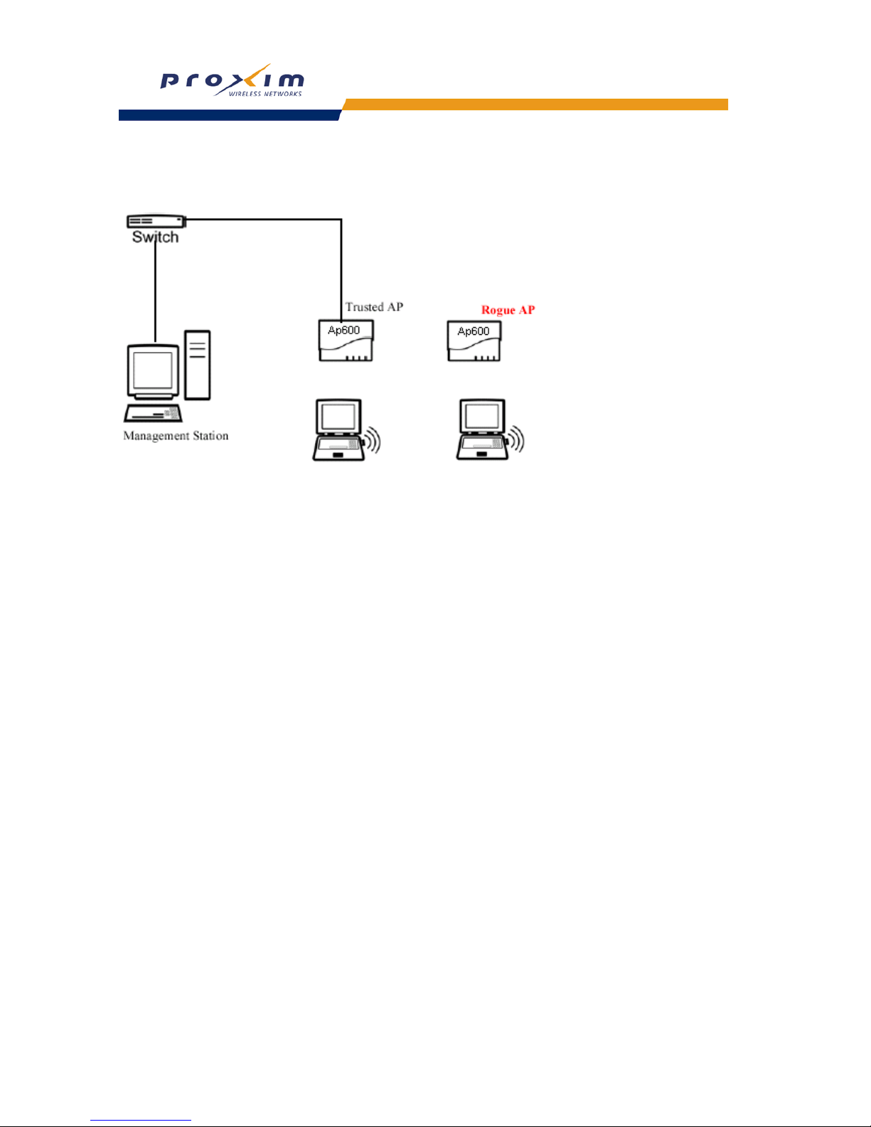
79
Performing Advanced Configuration
Example Rogue AP Detection Deployment
Figure 4-20 Example Rogue AP Detection Deployment
Additionally, the RAD scan results are maintained in a table that can be queried via SNMP. The system administrator
has to enable RAD on the Access Points in the wireless network and also configure the Trap Host on all these Access
Points to the IP address of the management station. The Access Points on detecting a new Access Point sends a RAD
Scan Result Trap to the management station.
An example network deployment is shown. The Trusted AP has Rogue Access Detection enabled and the trap host is
configured to be the management station. The Trusted AP on detecting the Rogue AP will send a trap to the
management station with the Channel and BSSID of the Rogue Access Point.
Configuring RAD
Perform this procedure to enable and configure RAD.
The RAD screen also displays the time of the last scan and the number of new access points detected in the last scan.
1. Enable the Security Alarm Group. Select the Security Alarm Group link from the RAD screen. Configure a Trap
Host to receive the list of access points detected during the scan.
2. Click Configure > Alarms > RAD.
3. Enable RAD by checking Enable Rogue AP Detection.
4. Enter the Scan Interval.
• The Scan Interval specifies the time period in minutes between scans and can be set to any value between 15
and 1440 minutes.
5. Click OK.
The results of the RAD scan be viewed in the Status page in the HTTP interface.
Page 82
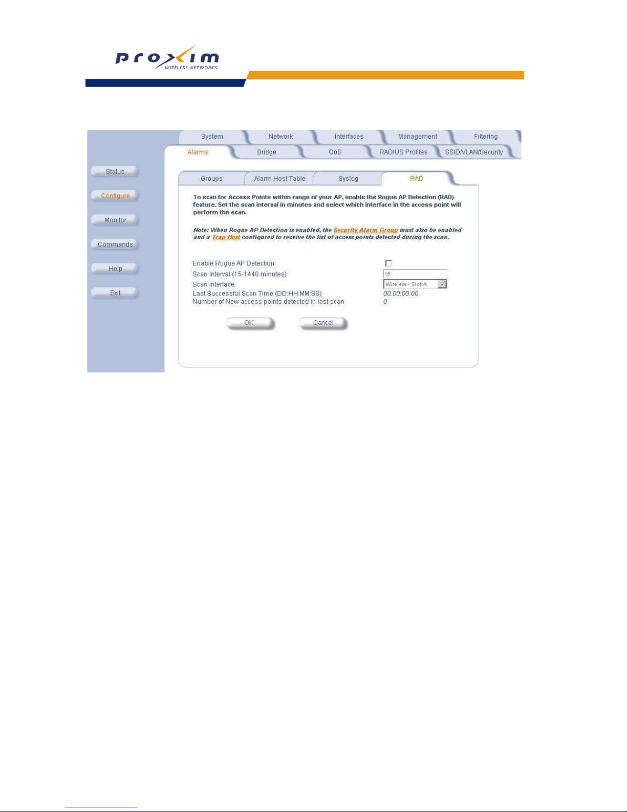
80
Performing Advanced Configuration
Figure 4-21 Rogue Access Point Detection Screen
Page 83

81
Performing Advanced Configuration
Bridge
The AP is a bridge between your wired and wireless networking devices. As a bridge, the functions performed by the
AP include:
• MAC address learning
• Forward and filtering decision making
• Spanning Tree protocol used for loop avoidance
Once the AP is connected to your network, it learns which devices are connected to it and records their MAC
addresses in the Learn Table. The table can hold up to 10,000 entries. To view the Learn Table, click on the Monitor
tab and select the Learn Table tab.
The Bridge tab has four sub-tabs.
–
Spanning Tree
– Storm Threshold
– Intra BSS
– Packet Forwarding (Pkt Fwd)
Spanning Tree
A Spanning Tree is used to avoid redundant communication loops in networks with multiple bridging devices. Bridges
do not have any inherent mechanism to avoid loops, because having redundant systems is a necessity in certain
networks. However, redundant systems can cause Broadcast Storms, multiple frame copies, and MAC address table
instability problems.
Complex network structures can create multiple loops within a network. The Spanning Tree configuration blocks
certain ports on AP devices to control the path of communication within the network, avoiding loops and following a
spanning tree structure.
For more information on Spanning Tree protocol, see Section 8.0 of the IEEE 802.1d standard. The Spanning Tree
configuration options are advanced settings. Proxim recommends that you leave these parameters at their default
values unless you are familiar with the Spanning Tree protocol.
Storm Threshold
Storm Threshold is an advanced Bridge setup option that you can use to protect the network against data overload by:
• Specifying a maximum number of frames per second as received from a single network device (identified by its
MAC address).
• Specifying an absolute maximum number of messages per port.
The Storm Threshold parameters allow you to specify a set of thresholds for each port of the AP, identifying separate
values for the number of broadcast messages/second and Multicast messages/second.
When the number of frames for a port or identified station exceeds the maximum value per second, the AP will ignore
all subsequent messages issued by the particular network device, or ignore all messages of that type.
– Address Threshold: Enter the maximum allowed number of packets per second.
– Ethernet Threshold:
Enter the maximum allowed number of packets per second.
– Wireless Threshold: Enter the maximum allowed number of packets per second.
Intra BSS
The wireless clients (or subscribers) that associate with a certain AP form the Basic Service Set (BSS) of a network
infrastructure. By default, wireless subscribers in the same BSS can communicate with each other. However, some
administrators (such as wireless public spaces) may wish to block traffic between wireless subscribers that are
associated with the same AP to prevent unauthorized communication and to conserve bandwidth. This feature
enables you to prevent wireless subscribers within a BSS from exchanging traffic.
Although this feature is generally enabled in public access environments, Enterprise LAN administrators use it to
conserve wireless bandwidth by limiting communication between wireless clients. For example, this feature prevents
peer-to-peer file sharing or gaming over the wireless network.
Page 84

82
Performing Advanced Configuration
To block Intra BSS traffic, set Intra BSS Traffic Operation to Block. To allow Intra BSS traffic, set Intra BSS Traffic
Operation to Passthru.
Packet Forwarding (Pkt Fwd)
The Packet Forwarding feature enables you to redirect traffic generated by wireless clients that are all associated to
the same AP to a single MAC address. This filters wireless traffic without burdening the AP and provides additional
security by limiting potential destinations or by routing the traffic directly to a firewall. You can redirect to a specific port
(Ethernet or WDS) or allow the bridge’s learning process (and the forwarding table entry for the selected MAC
address) to determine the optimal port.
NOTE
The gateway to which traffic will be redirected should be node on the Ethernet network. It should not be a
wireless client.
To configure interfaces for packet forwarding, specifying interface port(s) to which packets are redirected and a
destination MAC address, as follows:
1. Within the Packet Forwarding Configuration screen, check the box labeled Enable Packet Forwarding.
2. Specify a destination Packet Forwarding MAC Address. The AP will redirect all unicast, multicast, and broadcast
packets received from wireless clients to the address you specify.
3. Select a Packet Forwarding Interface Port from the drop-down menu. You can redirect traffic to:
– Any Interface (traffic is redirected to a port based on the bridge learning process)
– Ethernet
– A WDS connection (see
Wireless Distribution System (WDS) for details)
4. Click OK to save your changes.
QoS (Quality of Service)
This feature is not supported in the AP. Clicking on this tab displays the following message: “The Quality of Service
(QoS) feature is not implemented on the AP-600 and AP-2000.”
Page 85
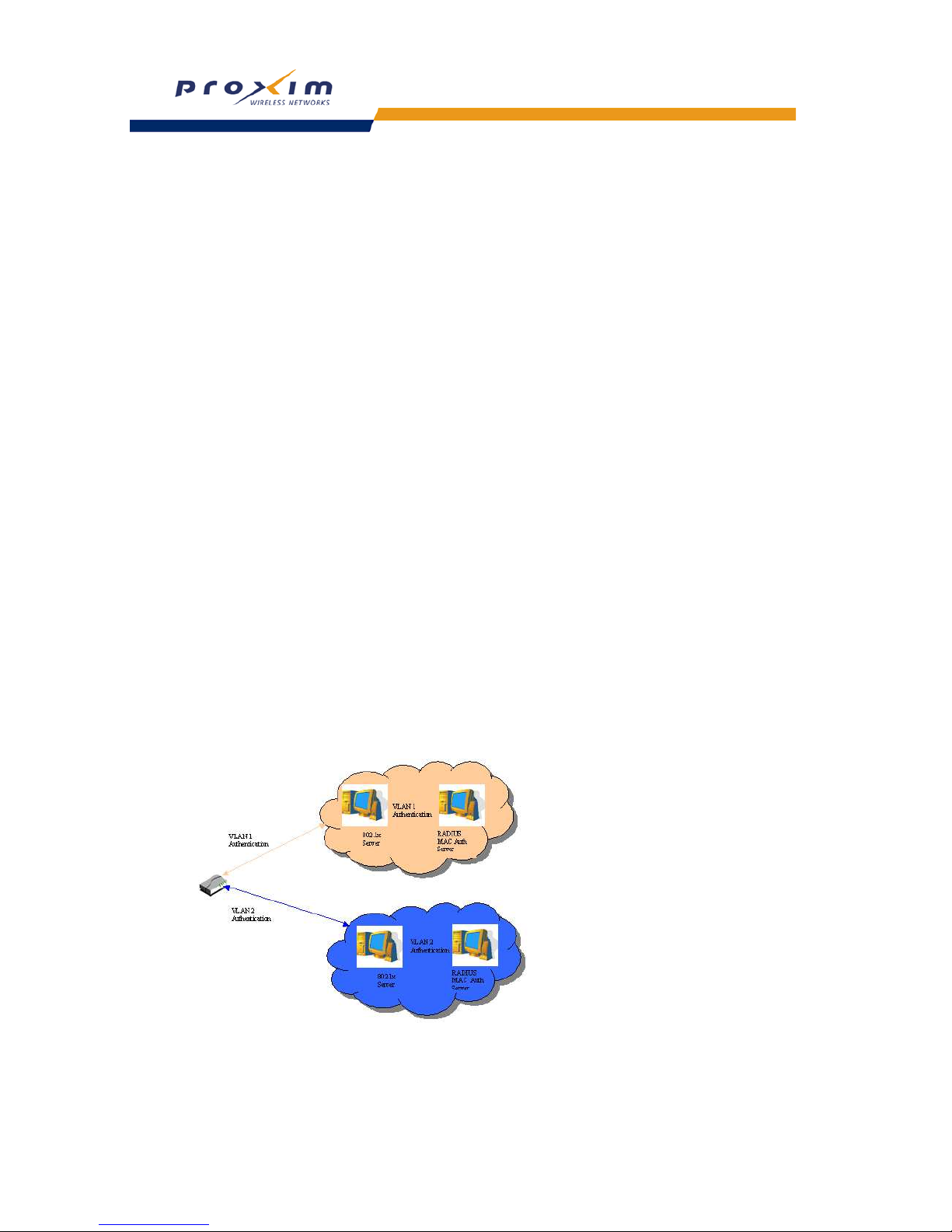
83
Performing Advanced Configuration
RADIUS Profiles
Configuring RADIUS Profiles on the AP define a profile for RADIUS Servers used by the system or by a VLAN. The
network administrator can define RADIUS Servers per Authentication Mode and per VLAN.
The AP communicates with the RADIUS server defined in a profile to provide the following features:
– MAC Access Control Via RADIUS Authentication
– 802.1x Authentication using RADIUS
– RADIUS Accounting
Also, RADIUS Based Management Access allows centralized user management.
The network administrator can configure default RADIUS authentication servers to be used on a system-wide basis, or
in networks with VLANs enabled the administrator can also configure separate authentication servers to be used for
MAC authentication, EAP authentication, or Accounting in each VLAN. You can configure the AP to communicate with
up to six different RADIUS servers per VLAN/SSID:
• Primary Authentication Server (MAC-based authentication)
• Back-up Authentication Server (MAC-based authentication)
• Primary Authentication Server (EAP/802.1x authentication)
• Back-up Authentication Server (EAP/802.1x authentication)
• Primary Accounting Server
• Back-up Accounting Server
The back-up servers are optional, but when configured, the AP will communicate with the back-up server if the primary
server is off-line. After the AP has switched to the backup server, it will periodically check the status of the primary
RADIUS server every five (5) minutes. Once the primary RADIUS server is again online, the AP automatically reverts
from the backup RADIUS server back to the primary RADIUS server. All subsequent requests are then sent to the
primary RADIUS server.
You can view monitoring statistics for each of the configured RADIUS servers.
RADIUS Servers per Authentication Mode and per VLAN
The user can configure separate RADIUS authentication servers for each authentication mode and for each SSID
(VLAN). For example:
• the user can configure separate RADIUS servers for RADIUS MAC authentication and 802.1x authentication
• the user can configure separate RADIUS servers for each VLAN: the Sales VLAN could support only WEP clients,
whereas the Marketing VLAN could support 802.1x and WEP clients.
Figure 4-22 RADIUS Servers per VLAN
This figure shows a network with separate authentication servers for each authentication type and for each VLAN. The
clients in VLAN 1 are authenticated using the authentication servers configured for VLAN 1. The type of authentication
AP
Page 86
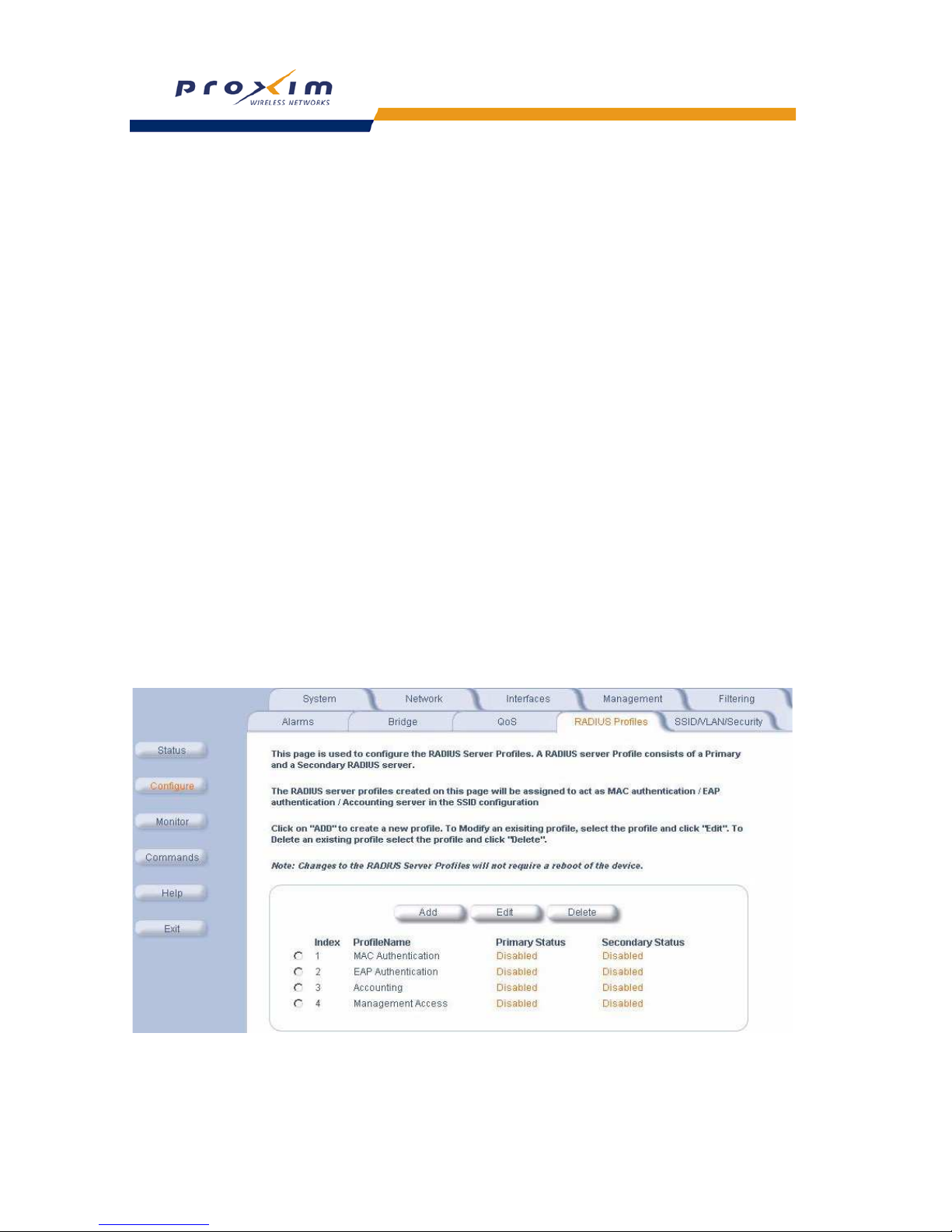
84
Performing Advanced Configuration
server used depends on whether the authentication is done for an 802.1x client or non-802.1x client. The clients in
VLAN 2 are authenticated using a different set of authentication servers configured for authenticating users in VLAN 2.
Authentication servers for each VLAN are configured as part of the configuration options for that VLAN. You can also
configure authentication servers on a system-wide basis; these are called the default authentication servers. For each
VLAN, the user could opt to use the default authentication servers, or to configure separate authentication servers to
be used for a particular authentication type in that VLAN.
RADIUS-based VLAN Assignment
The AP currently supports two methods of assigning a wireless client a VLAN ID. The wireless client can either be
assigned the static VLAN ID configured for the SSID the wireless client is associated to, or the wireless client can be
assigned a VLAN ID which is returned by the RADIUS server during authentication.
A VLAN ID can only be assigned to a wireless client by a RADIUS server if they are associated to an SSID that is
configured to a RADIUS-based authentication security mode/protocol (802.1X, WPA, 802.11i/WPA2, and RADIUS
based MAC Address Authentication). If the wireless client is associated to an SSID that does not provide
RADIUS-based authentication (such as None, WEP, WPA-PSK, and 802.11i/WPA2-PSK), then the wireless client will
be assigned the static VLAN ID configured for respective SSID. See
SSID/VLAN/Security for more information.
RADIUS Servers Enforcing VLAN Access Control
A RADIUS server can be used to enforce VLAN access control in two ways:
• Authorize the SSID the client uses to connect to the AP. The SSID determines the VLAN that the client gets
assigned to.
Assigning the user to a VLAN by specifying the VLAN membership information of the user.
Configuring RADIUS Profiles
A RADIUS server Profile consists of a Primary and a Secondary RADIUS server that get assigned to act as either
MAC Authentication servers, 802.1x/EAP Authentication servers, or Accounting Servers in the VLAN Configuration.
Refer to SSID/VLAN/Security.
The RADIUS Profiles tab allows you to add new RADIUS profiles or modify or delete existing profiles.
Figure 4-23 RADIUS Server Profiles
Page 87
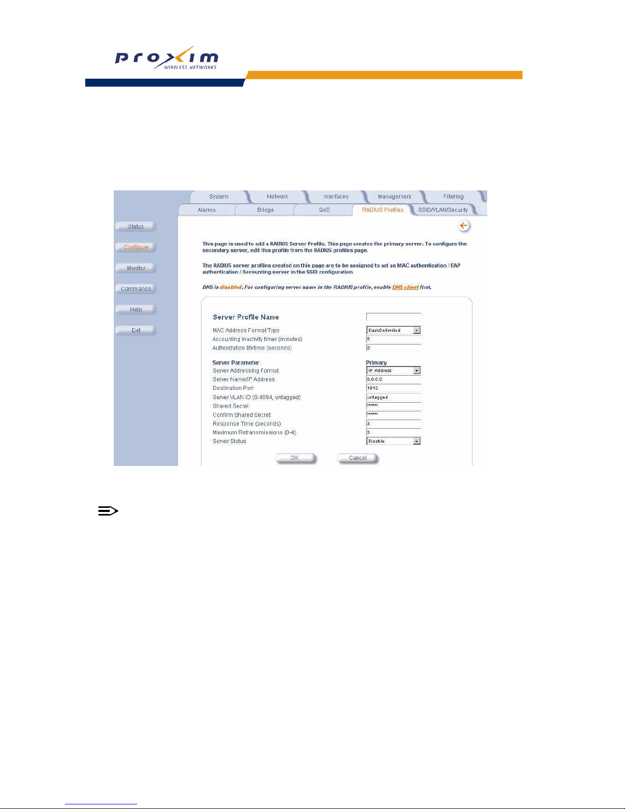
85
Performing Advanced Configuration
Adding or Modifying a RADIUS Server Profile
Perform the following procedure to add a RADIUS server profile and to configure its parameters.
1. Click Add to create a new profile. To Modify an existing profile, select the profile and click Edit. To delete an
existing profile, select the profile and click Delete. You cannot delete a RADIUS server profile if you are using it in
an SSID. Also, the four default RADIUS server profiles cannot be deleted.
Figure 4-24 Add RADIUS Server Profile
Configure the following parameters for the RADIUS Server profile:
NOTE
This page configures only the Primary RADIUS Server associated with the profile. After configuring these
parameters, save them by clicking OK. Then, to configure the Secondary RADIUS Server, edit the profile from
the main page.
• Server Profile Name: the profile name. This is the name used to associated a VLAN to the profile. Refer to
SSID/VLAN/Security.
• MAC Address Format Type: This parameter should correspond to the format in which the clients’ 12-digit MAC
addresses are listed within the RADIUS server. Available options are:
• Dash delimited: dash between each pair of digits: xx-yy-zz-aa-bb-cc
• Colon delimited: colon between each pair of digits: xx:yy:zz:aa:bb:cc
• Single dash delimited: dash between the sixth and seventh digits: xxyyzz-aabbcc
• No delimiters: No characters or spaces between pairs of hexidecimal digits: xxyyzzaabbcc
• Accounting Inactivity Timer: Enter the accounting inactivity timer. This parameter supports a value from 1-60
minutes. The default is 5 minutes.
• Authorization Lifetime: Enter the time, in seconds, each client session may be active before being automatically
re-authenticated. This parameter supports a value between 900 and 43200 seconds. The default is 900 sec.
• Server Addressing Format: select IP Address or Name. If you want to identify RADIUS servers by name, you
must configure the AP as a DNS Client. See DNS Client for details.
Page 88

86
Performing Advanced Configuration
• Server Name/IP Address: Enter the server’s name or IP address.
• Destination Port: Enter the port number which the AP and the server will use to communicate. By default,
RADIUS servers communicate on port 1812.
• Server VLAN ID: Indicates the VLAN that uses this RADIUS server profile. If VLAN is disabled, the text “VLAN is
disabled” will appear.
• Shared Secret and Confirm Shared Secret: Enter the password shared by the RADIUS server and the AP. The
same password must also be configured on the RADIUS server.
• Response Time (seconds): Enter the maximum time, in seconds, that the AP should wait for the RADIUS server
to respond to a request. The range is 1-10 seconds; the default is 3 seconds.
• Maximum Retransmissions (0-4): Enter the maximum number of times an authentication request may be
transmitted. The range is 0 to 4, the default is 3.
• Server Status: Select Enable from the drop-down box to enable the RADIUS Server Profile.
2. Click OK.
3. Select the Profile and click Edit to configure the Secondary RADIUS Server, if required.
4. Reboot the AP.
MAC Access Control Via RADIUS Authentication
If you want to control wireless access to the network and if your network includes a RADIUS Server, you can store the
list of MAC addresses on the RADIUS server rather than configure each AP individually. You can define a RADIUS
Profile that specifies the IP Address of the server that contains a central list of MAC Address values identifying the
authorized stations that may access the wireless network. You must specify information for at least the primary
RADIUS server. The back-up RADIUS server is optional.
NOTE
Each VLAN can be configured to use a separate RADIUS server (and backup server) for MAC authentication.
NOTE
Contact your RADIUS server manufacturer if you have problems configuring the server or have problems
using RADIUS authentication.
802.1x Authentication using RADIUS
You must configure a primary EAP/802.1x Authentication server to use 802.1x security. A back-up server is optional.
NOTE
Each VLAN can be configured to use a separate RADIUS server (and backup server) for 802.1x
authentication. 802.1x authentication (“EAP authentication”) can be separately enabled for each VLAN.
Page 89

87
Performing Advanced Configuration
RADIUS Accounting
Using an external RADIUS server, the AP can track and record the length of client sessions on the access point by
sending RADIUS accounting messages per RFC2866. When a wireless client is successfully authenticated, RADIUS
accounting is initiated by sending an “Accounting Start” request to the RADIUS server. When the wireless client
session ends, an “Accounting Stop” request is sent to the RADIUS server.
Session Length
Accounting sessions continue when a client reauthenticates to the same AP. Sessions are terminated when:
• A client disassociates.
• A client does not transmit any data to the AP for a fixed amount of time.
• A client is detected on a different interface.
If the client roams from one AP to another, one session is terminated and a new session is begun.
NOTE
This feature requires RADIUS authentication using MAC Access Control or 802.1x. Wireless clients
configured in the Access Point’s static MAC Access Control list are not tracked.
Page 90

88
Performing Advanced Configuration
SSID/VLAN/Security
The AP provides several security features to protect your network from unauthorized access.
Virtual Local Area Networks (VLANs) are logical groupings of network hosts. Defined by software settings, other VLAN
members or resources appear (to clients) to be on the same physical segment, no matter where they are attached on
the logical LAN or WAN segment. They simplify traffic flow between clients and their frequently-used or restricted
resources.
The AP uses Security Profiles to define allowed wireless clients, and authentication and encryption types and RADIUS
Profiles to define RADIUS Servers used by the system or by a VLAN.
The SSID/VLAN/Security tab contains the following sub-tabs:
•
Management VLAN
• Security Profiles
• MAC Access
• Wireless-A and Wireless-B
Management VLAN
VLAN Overview
Virtual Local Area Networks (VLANs) are logical groupings of network hosts. Defined by software settings, other VLAN
members or resources appear (to clients) to be on the same physical segment, no matter where they are attached on
the logical LAN or WAN segment. They simplify traffic flow between clients and their frequently-used or restricted
resources.
VLANs now extend as far as the reach of the access point signal. Clients can be segmented into wireless
sub-networks via SSID and VLAN assignment. A Client can access the network by connecting to an AP configured to
support its assigned SSID/VLAN.
AP devices are fully VLAN-ready; however, by default VLAN support is disabled. Before enabling VLAN support,
certain network settings should be configured, and network resources such as a VLAN-aware switch, a RADIUS
server, and possibly a DHCP server should be available.
Once enabled, VLANs are used to conveniently, efficiently, and easily manage your network in the following ways:
– Manage adds, moves, and changes from a single point of contact
– Define and monitor groups
– Reduce broadcast and multicast traffic to unnecessary destinations
• Improve network performance and reduce latency
– Increase security
• Secure network restricts members to resources on their own VLAN
• Clients roam without compromising security
VLAN tagged data is collected and distributed through an AP's wireless interface(s) based on Network Name (SSID).
An Ethernet port on the access point connects a wireless cell or network to a wired backbone. The access points
communicate across a VLAN-capable switch that analyzes VLAN-tagged packet headers and directs traffic to the
appropriate ports. On the wired network, a RADIUS server authenticates traffic and a DHCP server manages IP
addresses for the VLAN(s). Resources like servers and printers may be present, and a hub may include multiple APs,
extending the network over a larger area.
In this figure, the numbered items correspond to the following components:
1. VLAN-enabled access point
2. VLAN-aware switch (IEEE 802.1Q uplink)
3. AP management via wired host (SNMP, Web interface or CLI)
4. DHCP Server
5. RADIUS Server
6. VLAN 1
7. VLAN 2
Page 91
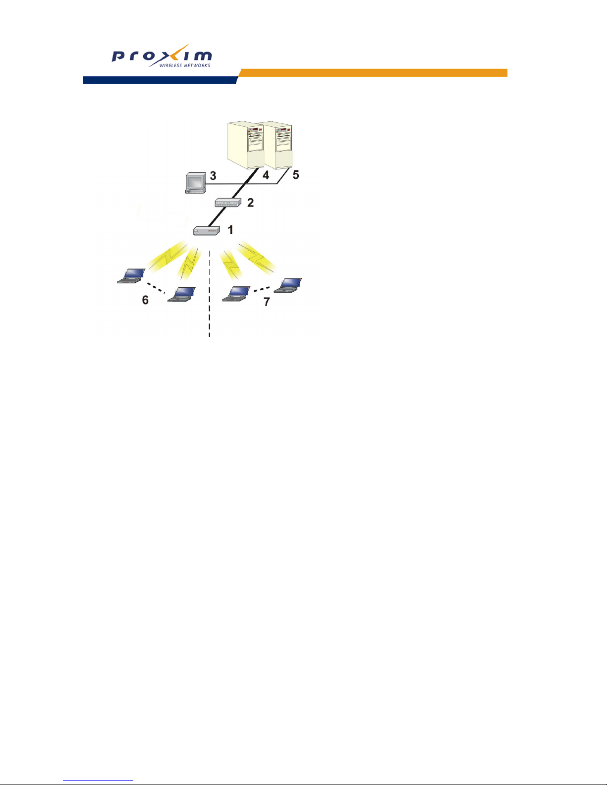
89
Performing Advanced Configuration
Figure 4-25 Components of a typical VLAN
VLAN Workgroups and Traffic Management
Access Points that are not VLAN-capable typically transmit broadcast and multicast traffic to all wireless Network
Interface Cards (NICs). This process wastes wireless bandwidth and degrades throughput performance. In
comparison, VLAN-capable AP is designed to efficiently manage delivery of broadcast, multicast, and unicast traffic to
wireless clients.
The AP assigns clients to a VLAN based on a Network Name (SSID). The AP can support up to 16 VLAN/SSID pairs
per radio (based on model type).
The ability to configure up to 16 VLAN/SSID pairs and to configure a security profile per SSID is available only
for AP-600a/b/g and AP-600b/g.
The AP matches packets transmitted or received to a network name with the associated VLAN. Traffic received by a
VLAN is only sent on the wireless interface associated with that same VLAN. This eliminates unnecessary traffic on
the wireless LAN, conserving bandwidth and maximizing throughput.
In addition to enhancing wireless traffic management, the VLAN-capable AP supports easy assignment of wireless
users to workgroups. In a typical scenario, each user VLAN represents a workgroup; for example, one VLAN could be
used for an EMPLOYEE workgroup and the other, for a GUEST workgroup.
In this scenario, the AP would assign every packet it accepted to a VLAN. Each packet would then be identified as
EMPLOYEE or GUEST, depending on which wireless NIC received it. The AP would insert VLAN headers or “tags”
with identifiers into the packets transmitted on the wired backbone to a network switch.
Finally, the switch would be configured to route packets from the EMPLOYEE workgroup to the appropriate corporate
resources such as printers and servers. Packets from the GUEST workgroup could be restricted to a gateway that
allowed access to only the Internet. A member of the GUEST workgroup could send and receive e-mail and access the
Internet, but would be prevented from accessing servers or hosts on the local corporate network.
Typical User VLAN Configurations
VLANs segment network traffic into workgroups, which enable you to limit broadcast and multicast traffic. Workgroups
enable clients from different VLANs to access different resources using the same network infrastructure. Clients using
the same physical network are limited to those resources available to their workgroup.
The AP can segment users into a maximum of 16 different workgroups (32 if using two cards in a Dual-radio AP)
based on an SSID/VLAN pair (also referred as a VLAN Workgroup or a Sub-network).
The ability to configure up to 16 VLAN/SSID pairs and to configure a security profile per SSID is available only
for AP-600a/b/g and AP-600b/g.
Page 92

90
Performing Advanced Configuration
The three primary scenarios for using VLAN workgroups are as follows:
1. VLAN disabled: Your network does not use VLANs, and you cannot configure the AP to use multiple SSIDs.
2. VLAN enabled, each VLAN workgroup uses a different VLAN ID Tag
3. VLAN enabled, a mixture of Tagged and Untagged workgroups
Enabling/Disabling VLAN Protocol
Control Access to the AP
Management access to the AP can easily be secured by making management stations or hosts and the AP itself
members of a common VLAN. Simply configure a non-zero management VLAN ID and enable VLAN to restrict
management of the AP to members of the same VLAN.
CAUTION
!
If a non-zero management VLAN ID is configured then management access to the AP is restricted to wired or
wireless hosts that are members of the same VLAN. Ensure your management platform or host is a member
of the same VLAN before attempting to manage the AP.
1. Click Configure > SSID/VLAN/Security.
2. Set the VLAN Management ID to a value between -1 and 4094 (a value of 0 disables VLAN management).
3. Place a check mark in the Enable VLAN Protocol box.
Provide Access to a Wireless Host in the Same Workgroup
The VLAN feature can allow wireless clients to manage the AP. If the VLAN Management ID matches a VLAN User ID,
then those wireless clients who are members of that VLAN will have AP management access.
CAUTION
!
Once a VLAN Management ID is configured and is equivalent to one of the VLAN User IDs on the AP, all
members of that User VLAN will have management access to the AP. Be careful to restrict VLAN membership
to those with legitimate access to the AP.
1. Click Configure > SSID/VLAN/Security.
2. Set the VLAN Management ID to use the same VLAN ID as one of the configured SSID/VLAN pairs. See
Typical
User VLAN Configurations for details.
3. Place a check mark in the Enable VLAN Protocol box.
Disable VLAN Management
1. Click Configure > SSID/VLAN/Security.
2. Remove the check mark from the Enable VLAN Protocol box to disable all VLAN functionality.
Page 93
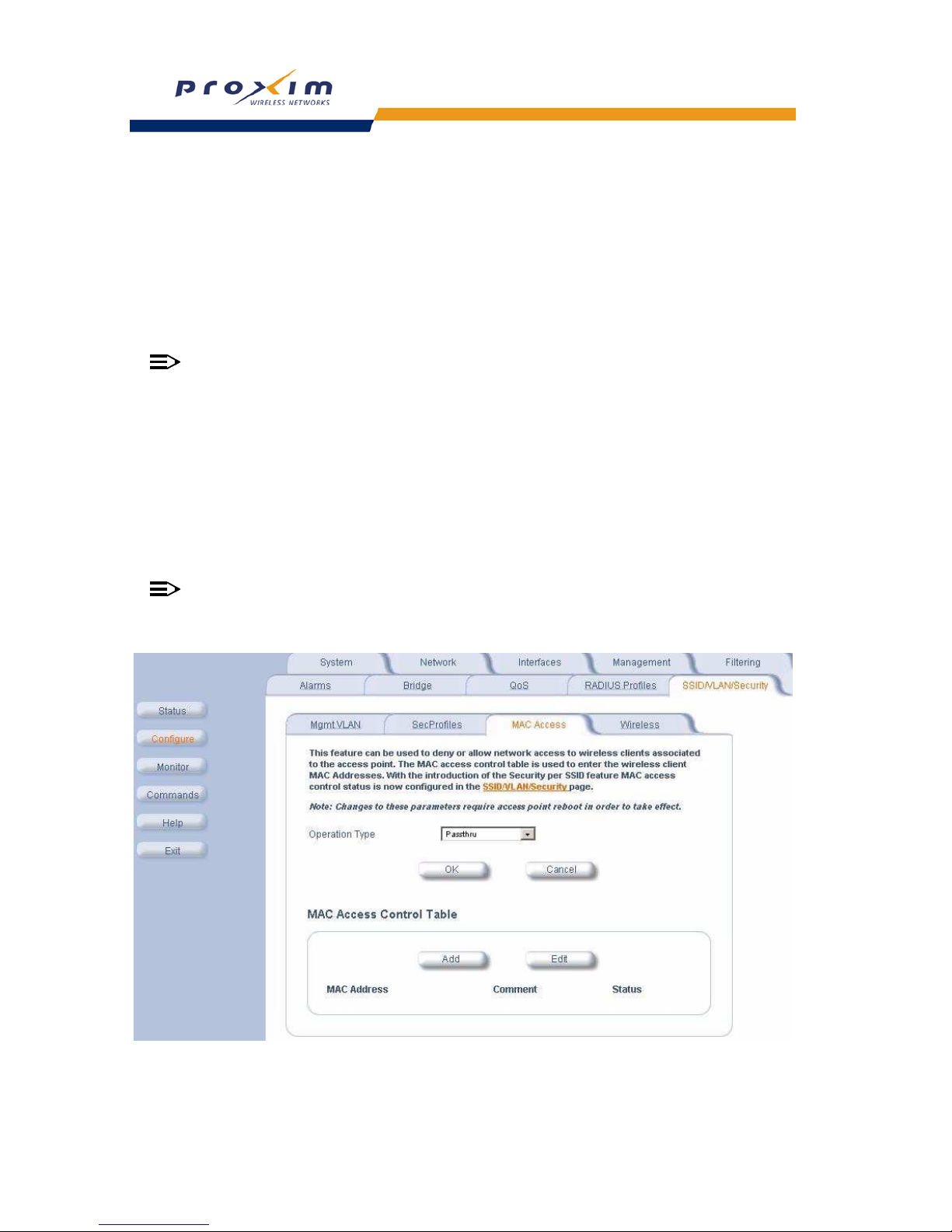
91
Performing Advanced Configuration
MAC Access
The MAC Access sub-tab allows you to build a list of stations, identified by their MAC addresses, authorized to access
the network through the AP. The list is stored inside each AP within your network. Note that you must reboot the AP for
any changes to the MAC Access Control Table to take effect.
The “MAC ACL Status” parameter (configurable on the SSID/VLAN -> Wireless sub-tab) is per VLAN if VLAN
Management is enabled. All other parameters besides “MAC ACL Status” are configured per AP, even if VLAN is
enabled.
Configuring MAC Access
NOTE
MAC Access Control status is enabled or disabled when configuring each Security Profile.
• Operation Type: Choose between Passthru and Block. This determines how the stations identified in the MAC
Access Control Table are filtered.
• If set to Passthru, only the addresses listed in the Control Table will pass through the bridge.
• If set to Block, the bridge will block traffic to or from the addresses listed in the Control Table.
• MAC Access Control Table: Click Add to create a new entry. Click Edit to change an existing entry. Each entry
contains the following field:
– MAC Address: Enter the wireless client’s MAC address.
– Comment: Enter an optional comment such as the client’s name.
• Status: The entry is enabled automatically when saved (so the Status field is only visible when editing an
entry). You can also disable or delete entries by changing this field’s value.
NOTE
For larger networks that include multiple Access Points, you may prefer to maintain this list on a centralized
location using the MAC Access Control Via RADIUS Authentication.
Figure 4-26 MAC Access Configuration Screen
Page 94

92
Performing Advanced Configuration
Security Profiles
The AP supports the following Security features:
• WEP Encryption: The original encryption technique specified by the IEEE 802.11 standard.
• 802.1x Authentication: An IEEE standard for client authentication.
• Wi-Fi Protected Access (WPA): A new standard that provides improved encryption security over WEP.
WEP Encryption
The IEEE 802.11 standards specify an optional encryption feature, known as Wired Equivalent Privacy or WEP, that is
designed to provide a wireless LAN with a security level equal to what is found on a wired Ethernet network. WEP
encrypts the data portion of each packet exchanged on an 802.11 network using an Encryption Key (also known as a
WEP Key).
When Encryption is enabled, two 802.11 devices must have the same Encryption Keys and both devices must be
configured to use Encryption in order to communicate. If one device is configured to use Encryption but a second
device is not, then the two devices will not communicate, even if both devices have the same Encryption Keys.
• An 802.11b AP supports 64-bit and 128-bit encryption:
– For 64-bit encryption, an encryption key is 10 hexadecimal characters (0-9 and A-F) or 5 ASCII characters
(see
ASCII Character Chart).
– For 128-bit encryption, an encryption key is 26 hexadecimal characters or 13 ASCII characters.
• An 802.11a or 802.11b/g AP supports 64-bit, 128-bit, and 152-bit encryption:
– For 64-bit encryption, an encryption key is 10 hexadecimal characters (0-9 and A-F) or 5 ASCII characters
(see ASCII Character Chart).
– For 128-bit encryption, an encryption key is 26 hexadecimal characters or 13 ASCII characters.
– For 152-bit encryption, an encryption key is 32 hexadecimal characters or 16 ASCII characters.
802.1x Authentication
IEEE 802.1x is a standard that provides a means to authenticate and authorize network devices attached to a LAN
port. A port in the context of IEEE 802.1x is a point of attachment to the LAN, either a physical Ethernet connection or
a wireless link to an Access Point. 802.1x requires a RADIUS server and uses the Extensible Authentication Protocol
(EAP) as a standards-based authentication framework, and supports automatic key distribution for enhanced security.
The EAP-based authentication framework can easily be upgraded to keep pace with future EAP types.
Popular EAP types include:
• EAP-Message Digest 5 (MD5): Username/Password-based authentication; does not support automatic key
distribution
• EAP-Transport Layer Security (TLS): Certificate-based authentication (a certificate is required on the server and
each client); supports automatic key distribution
• EAP-Tunneled Transport Layer Security (TTLS): Certificate-based authentication (a certificate is required on the
server; a client’s username/password is tunneled to the server over a secure connection); supports automatic key
distribution
• PEAP - Protected EAP with MS-CHAP v2: Secure username/password-based authentication; supports automatic
key distribution
Different servers support different EAP types and each EAP type provides different features. Refer to the
documentation that came with your RADIUS server to determine which EAP types it supports.
NOTE
The AP supports the following EAP types when Authentication Mode is set to 802.1x, WPA or 802.11i
(WPA2): EAP-TLS, PEAP, and EAP-TTLS. When Authentication Mode is set to Mixed, the AP supports the
following EAP types: EAP-TLS, PEAP, EAP-TLLS, and EAP-MD5 (MD5 does not support automatic key
distribution; therefore, if you choose this method you need to manually configure each client with the network's
encryption key).
Page 95
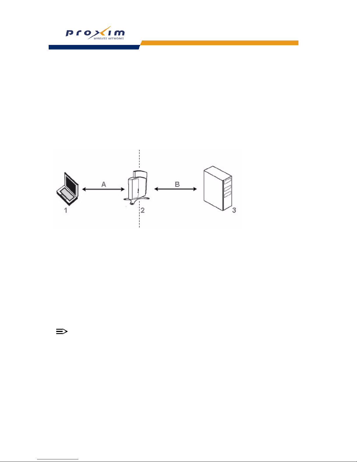
93
Performing Advanced Configuration
Authentication Process
There are three main components in the authentication process. The standard refers to them as:
1. supplicant (client PC)
2. authenticator (Access Point)
3. authentication server (RADIUS server)
When using Authentication Mode to 802.1x, WPA, Mixed mode (802.1x and WEP), or 802.11i, you need to configure
your RADIUS server for authentication purposes.
Prior to successful authentication, an unauthenticated client PC cannot send any data traffic through the AP device to
other systems on the LAN. The AP inhibits all data traffic from a particular client PC until the client PC is authenticated.
Regardless of its authentication status, a client PC can always exchange 802.1x messages in the clear with the AP
(the client begins encrypting data after it has been authenticated).
Figure 4-27 RADIUS Authentication Illustrated
The AP acts as a pass-through device to facilitate communications between the client PC and the RADIUS server. The
AP (2) and the client (1) exchange 802.1x messages using an EAPOL (EAP Over LAN) protocol (A). Messages sent
from the client station are encapsulated by the AP and transmitted to the RADIUS (3) server using EAP extensions (B).
Upon receiving a reply EAP packet from the RADIUS, the message is typically forwarded to the client, after translating
it back to the EAPOL format. Negotiations take place between the client and the RADIUS server. After the client has
been successfully authenticated, the client receives an Encryption Key from the AP (if the EAP type supports
automatic key distribution). The client uses this key to encrypt data after it has been authenticated.
For 802.11a and 802.11b/g clients that communicate with an AP, each client receives its own unique encryption key;
this is known as Per User Per Session Encryption Keys.
Wi-Fi Protected Access (WPA)
Wi-Fi Protected Access (WPA) is a security standard designed by the Wi-Fi Alliance in conjunction with the Institute of
Electrical and Electronics Engineers (IEEE). THE AP supports WPA2, based on the IEEE 802.11i security standard.
NOTE
For Single-radio APs: WPA is available for AP-600a/b/g and AP-600b/g (or APs that have an 802.11a/b/g or
802.11b/g upgrade kit). WPA is NOT available for the AP-600a or AP-600b. Note that while you can select
WPA on AP-600a units, WPA is not supported for the AP-600a unless you have installed an 802.11a/b/g
upgrade kit.
WPA is a replacement for Wired Equivalent Privacy (WEP), the encryption technique specified by the original 802.11
standard. WEP has several vulnerabilities that have been widely publicized. WPA addresses these weaknesses and
provides a stronger security system to protect wireless networks.
WPA provides the following new security measures not available with WEP:
• Improved packet encryption using the Temporal Key Integrity Protocol (TKIP) and the Michael Message Integrity
Check (MIC).
• Per-user, per-session dynamic encryption keys:
Page 96

94
Performing Advanced Configuration
– Each client uses a different key to encrypt and decrypt unicast packets exchanged with the AP
– A client's key is different for every session; it changes each time the client associates with an AP
– The AP uses a single global key to encrypt broadcast packets that are sent to all clients simultaneously
– Encryption keys change periodically based on the Re-keying Interval parameter
– WPA uses 128-bit encryption keys
• Dynamic Key distribution
– The AP generates and maintains the keys for its clients
– The AP securely delivers the appropriate keys to its clients
• Client/server mutual authentication
– 802.1x
– Pre-shared key (for networks that do not have an 802.1x solution implemented)
NOTE
For more information on WPA, see the Wi-Fi Alliance Web site at http://www.wi-fi.org.
The AP supports the following WPA authentication modes:
• WPA: The AP uses 802.1x to authenticate clients. You should only use an EAP that supports mutual authentication
and session key generation, such as EAP-TLS, EAP-TTLS, and PEAP. See 802.1x Authentication for details.
• WPA-PSK (Pre-Shared Key): For networks that do not have 802.1x implemented, you can configure the AP to
authenticate clients based on a Pre-Shared Key. This is a shared secret that is manually configured on the AP and
each of its clients. The Pre-Shared Key must be 256 bits long, which is 64 hexadecimal digits. The AP also
supports a PSK Pass Phrase option to facilitate the creation of the Pre-Shared Key (so a user can enter an
easy-to-remember phrase rather than a string of characters).
• 802.11i (also known as WPA2): The AP authenticates clients according to the 802.11i draft standard, using 802.1x
authentication, an AES cipher, and re-keying.
• 802.11i-PSK (also known as WPA2 PSK): The AP uses an AES cipher, and authenticates clients based on a
Pre-Shared Key. The Pre-Shared Key must be 256 bits long, which is either 64 hexadecimal digits. The AP also
supports a PSK Pass Phrase option to facilitate the creation of the Pre-Shared Key (so a user can enter an
easy-to-remember phrase rather than a string of characters).
Authentication Protocol Hierarchy
There is a hierarchy of authentication protocols defined for the AP.
The hierarchy is as follows, from Highest to lowest:
• 802.1x authentication
• MAC Access Control via RADIUS Authentication
• MAC Access Control through individual APs' MAC Access Control Lists
If you have both 802.1x and MAC authentication enabled, the 802.1x results will take effect. This is required in
order to propagate the WEP keys to the clients in such cases. Once you disable 802.1x on the AP, you will see
the effects of MAC authentication.
VLANs and Security Profiles
The AP600allows you to segment wireless networks into multiple sub-networks based on Network Name (SSID) and
VLAN membership. A Network Name (SSID) identifies a wireless network. Clients associate with Access Points that
share an SSID. During installation, the
Setup Wizard prompts you to configure a Primary Network Name for each
wireless interface.
After initial setup and once VLAN is enabled, the AP can be configured to support up to 16 SSIDs per wireless
interface to segment wireless networks based on VLAN membership.
Each VLAN can be associated to a Security Profile and RADIUS Server Profiles. A Security Profile defines the allowed
wireless clients, and authentication and encryption types. Refer to
VLANs and Security Profiles for configuration
details.
The ability to configure up to 16 VLAN/SSID pairs and to configure a security profile per SSID is available only
for AP-600a/b/g and AP-600b/g.
Page 97
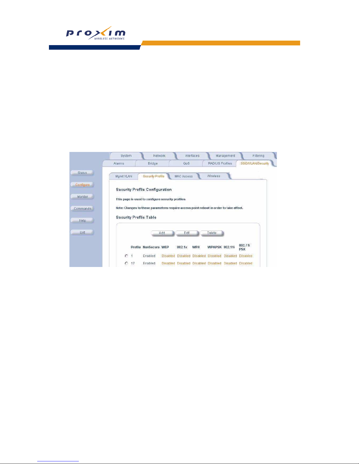
95
Performing Advanced Configuration
Configuring Security Profiles
Security policies can be configured and applied on the AP as a whole, or on a per VLAN basis. When VLAN is disabled
on the AP, the user can configure a security profile for each interface of the AP. When VLANs are enabled and Security
per SSID is enabled, the user can configure a security profile for each VLAN.
The user defines a security policy by specifying one or more values for the following parameters:
• Wireless STA types (WPA station, 802.11i station, 802.1x station, WEP station) that can associate to the AP.
• Authentication mechanisms (802.1x, RADIUS MAC authentication) that are used to authenticate clients for each
type of station.
• Cipher Suites (CCMP, TKIP, WEP) used for encapsulating the wireless data for each type of station.
Up to 16 security profiles can be configured per wireless interface.
1. Click Configure -> SSID/VLAN/Security -> Security Profile.
Figure 4-28 Security Profile Sub-tab
2. Click Add in the Security Profile Table to create a new entry. To modify an existing profile, select the profile and
click Edit. To delete an existing profile, select the profile and click Delete. You cannot delete a Security Profile used
in an SSID. Also, the first Security Profile (index 1.1 to 1.7) cannot be deleted.
3. Configure one or more types of wireless stations (security modes) that are allowed access to the AP under the
security profile. The WEP/PSK parameters are separately configurable for each security mode. To enable a
security mode in the profile (Non Secure Station, WEP Station, 802.1x Station, WPA Station, WPA-PSK Station,
802.11i Station, 802.11i-PSK Station), check the box next to the mode. See
Figure 4-27 on page 92.
If the security mode selected in a profile is WEP, WPA-PSK, or 802.11i-PSK, then you must configure the WEP or
Pre-Shared Keys.
4. Configure the parameters as follows for each enabled security mode. Refer to Figure 4-27 on page 92.
• Non Secure Station:
• Authentication Mode: None. The AP allows access to Stations without authentication.
• Non secure station should be used only with WEP or 802.1x security mode.
• Cipher: None
• WEP Station:
• Authentication Mode: None
• Cipher: WEP
• Encryption Key 0, Encryption Key 1, Encryption Key 2, Encryption Key 3
• Encryption Transmit Key: select Key 0, Key 1, Key 2, or Key 3
• 802.1x Station:
Page 98

96
Performing Advanced Configuration
• Authentication Mode: 802.1x
• Cipher: WEP
• Encryption Key Length: 64 or 128 Bits.
• If 802.1x is enabled simultaneously with WEP, the 802.1x Station’s encryption key length is determined by
the WEP encryption key.
• WPA Station:
• Authentication Mode: 802.1x
• Cipher: TKIP
• WPA-PSK Station:
• Authentication Mode: PSK
• Cipher: TKIP
• PSK Passphrase: an 8-63 character user-defined phrase. It is recommended a passphrase of at least 13
characters, including both letters and numbers, and upper and lower case characters to ensure that the
generated key cannot be easily deciphered by network infiltrators.
• 802.11i Station:
• Authentication Mode: 802.1x
• Cipher: AES
• 802.11i-PSK Station:
• Authentication Mode: PSK
• Cipher: AES
• PSK Passphrase: an 8-63 character user-defined phrase. It is recommended a passphrase of at least 13
characters, including both letters and numbers, and upper and lower case characters to ensure that the
generated key cannot be easily deciphered by network infiltrators.
5. When finished configuring all parameters, click OK.
6. If you selected a Security Mode of 802.1x Station, WPA Station, or 802.11i Station, you must configure a RADIUS
802.1x/EAP server. Refer to the
Configuring RADIUS Profiles section.
Security Profile 1 will be used by default for all wireless interfaces.
7. Refer to the following section for advanced VLAN configuration options:
Adding or Modifying an SSID/VLAN with
VLAN Protocol Disabled and Adding or Modifying an SSID/VLAN with VLAN Protocol Enabled.
8. Reboot the AP.
Page 99
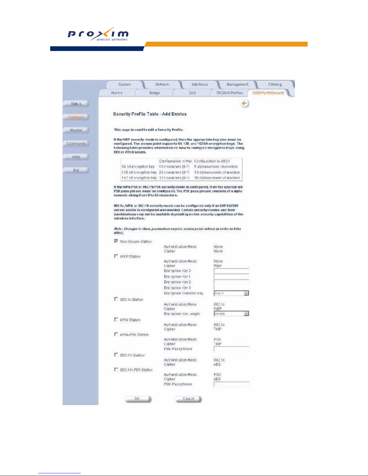
97
Performing Advanced Configuration
Figure 4-29 Security Profile Table - Add Entries
Page 100
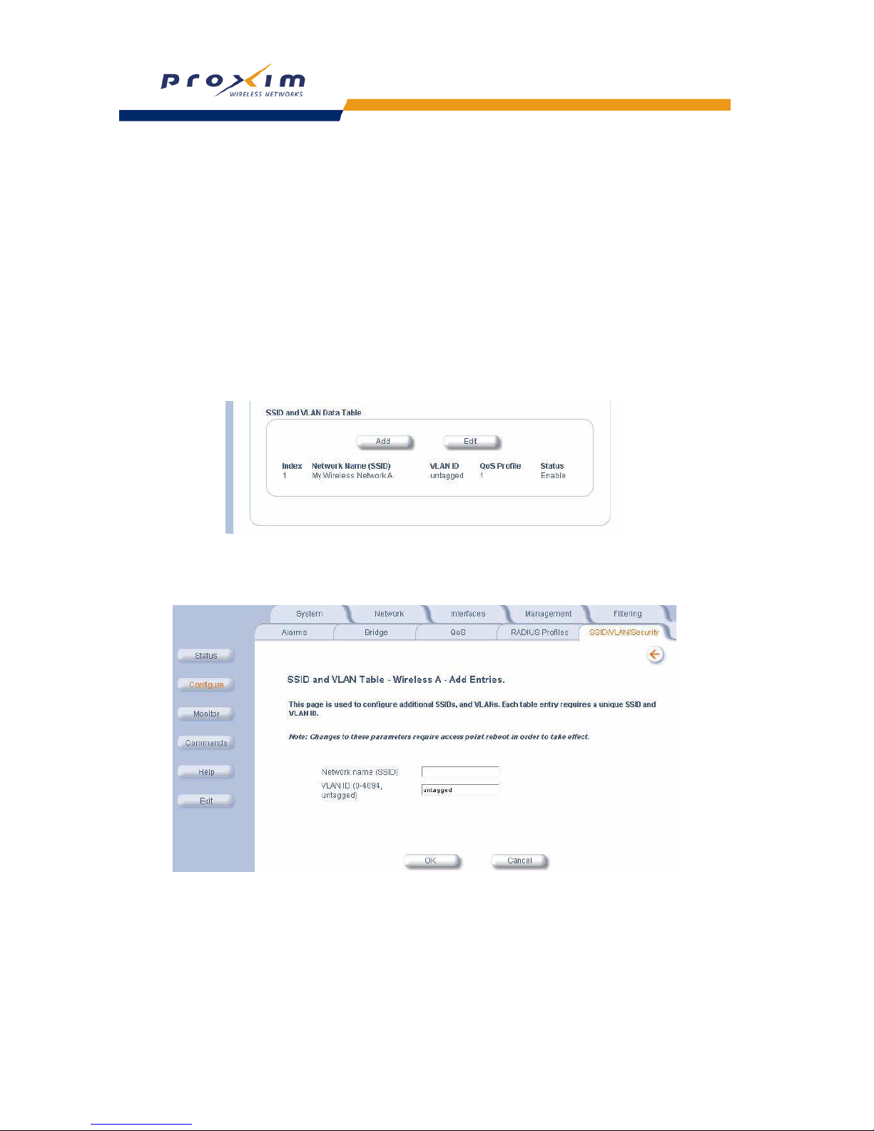
98
Performing Advanced Configuration
Wireless
Each SSID/VLAN can have its own Security Profile that defines its security mode, authentication mechanism, and
encryption, so that customers can have multiple types of clients (non-WEP, WEP, 802.1x, WPA) on the same system,
but separated per VLAN. Refer to the
Security Profiles section for more information. These parameters are
configurable from the Wireless sub-tab.
Adding or Modifying an SSID/VLAN with VLAN Protocol Disabled
1. Click on SSID/VLAN/Security > Wireless-.
This tab allows you to select the index of the SSID/VLAN to be added or edited. It also allows you to configure the
RADIUS Accounting and Authentication Status, the MAC ACL Status, the Rekeying Interval, the Security Profile,
and the RADIUS Server Profiles for the VLAN.
2. Scroll down to the SSID and VLAN table
3. Click Add to configure additional SSIDs, VLANs, and their associated security profiles and RADIUS server
profiles, or click Edit to modify an existing VLAN/SSID. See
Figure 4-28.
Figure 4-30 SSID and VLAN Table
The Add Entry or Edit Entry screen appears. See Figure 4-29 and Figure 4-30 on page 94.
Figure 4-31 SSID/VLAN Add Entries Screen (VLAN Protocol Disabled)
 Loading...