

ORiNG TPS-1080-M12, TPS-1080-M12-BP2-24V, TPS-1080-M12-BP2, TPS-1080-M12-24V Quick Installation Manual
Page 1
Quick InstallationGuide
Version 1.0
Quick Installation Guide
Introduction
PRINTED ON RECYCLED PAPER
QIG
The and are unmanaged PoE
Ethernet switches with 8x10/100Base-T(X)P.S.E. ports.Designed for
industrial applications,such as rollingstock, vehicle, andrailway
applications, these two models boast EN50155compliance and M12
connectors toensure tight androbust connections, andguarantee reliable
operation againstenvironmental disturbances, suchas vibration andshock.
The P.S.E. portsare able toprovide sufficient powerfor those power-hungry
devices withup to 30W per port.Therefore, you canattach an IEEE802.3atcompliant deviceto the switchwithout requiring additionalpower. The-BP2
model alsoprovides two setsof bypass portsthat ensure constantnetwork
connectivity duringpower failure. Evenif the switchloses power, trafficwill
continue toflow unimpeded throughthe link.
TPS-1080-M12/-24V TPS-1080-M12-BP2/-24V
Package Contents
Installation
Wall-mount
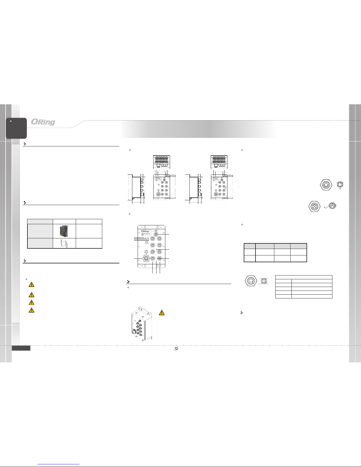
The devicecan be fixedto the wall.Follow the stepsbelow to installthe device onthe wall.
Hold the evice upright against the wall
Insert four screws through the large opening of the keyhole-shaped apertures at the
top and bottom of the unit and fastenthe screw tothe wall witha screwdriver.
Slide the evice downwards and tighten the four screws for added stability.
Step 1:
Step 2:
Step 3:dd
The deviceis shipped withthe following items.If any ofthese items ismissing
or damaged, please contact your customer servicerepresentative for
assistance.
Preparation
Before youbegin installing thedevice, make sureyou have allof the package
contents availableand a PCwith Microsoft InternetExplorer 6.0 orlater, for
using web-basedsystem management tools.
Elevated OperatingAmbient:
ReducedAir Flow:
Mechanical Loading:
Circuit Overloading:
If installedin a closed environment, makesure
the operating ambient temperature is compatible with the maximum
ambient temperature (Tma) specified by the manufacturer.
Make surethe amount ofair flow requiredfor safe operation
of theequipment is notcompromised during installation.
Make surethe mounting ofthe equipment is not in a
hazardous conditiondue to unevenmechanical loading.
Consideration shouldbe given tothe connection ofthe
equipment tothe supply circuitand the effectthat overloading ofthe circuits
might haveon overcurrent protectionand supply wiring.Appropriate
consideration ofequipment nameplate ratingsshould be used when addressing
this concern.
Safety & Warnings
For pinassignments of power,console andrelay output ports,please refer tothe following tables.
Contents
TPS-1080-M12 or
TPS-1080-M12-BP2 or
TPS-1080-M12-24V or
TPS-1080-M12-BP2-24V
Pictures Number
1
QIG
1
Dimension
TPS-1080-M12/-24V TPS-1080-M12-BP2/-24V
Panel Layouts
Front View
1. Powerstatus LED
2. Power1status LED
3. Power2status LED
4. FaultLED
5. Power input port
6.Relayoutputport
7. LANport LNK/ACT LED
8. LANport Duplex/Collision LED
9. Ethernetports
(P5-P8 ofTPS-1080-M12-BP2/-24V are bypassports)
10. PoEstatus LED
Wiring
Grounding
Grounding andwire routing helplimit the effectsof noise dueto electromagnetic interference
(EMI). Runthe ground connectionfrom the groundingpin on thepower connector tothe grounding
surface priorto connecting devices.
Power portpinouts
The devicesupports two setsof power suppliesand uses theM23 5-pin
female connector on the front panel for the dual power inputs.
Insert a power cableto the powerconnector on thedevice.
Rotate theouter ring ofthe cable connectoruntil a snug fit is
achieved. Make sure the connection is tight.
Step 1:
Step 2:
V1+
V1-
V2+
V2-
Relay outputport pinouts
Relay
N.C.
3A@24VDC
Network Connection
The switchhas eight 10/100Base-T(X)Ethernet ports in the form of M12 connector. These
ports are PoE-enabled, and thus can deliver power over the same Ethernet cable.
Depending onthe link type,the switch usesCAT 3,4, 5,5e UTPcables to connectto network
devices (PCs,servers, switches, routers,or hubs). Pleaserefer to thefollowing table forcable
specifications.
TPS-1080-M12 Series
TPS-1080-M12 Series
1907-2-29-TPS1080M12-1.0
Switch
EN50155
EN50155 8-port unmanaged
PoE Ethernet switch
INDUSTRIAL
125.0
196.0
R2.5
R4.00
155.8
65.0 21.3
15.0
7.50
168.4
56.5
86.0
TPS-1080-M12-BP2
FaultPWR2
Power
PWR1PWR
Relay
N.C.
3A@24VDC
RelayOutput
V1+
V1-
V2+
V2-
Power
Failure
Bypass
125.0
196.0
R2.5
R4.00
155.8
65.0 21.3
15.0
7.50
168.4
56.5
86.0
TPS-1080-M12
FaultPWR2
Power
PWR1PWR
Relay
N.C.
3A@24VDC
RelayOutput
V1+
V1-
V2+
V2-
1
2
3
4
5
6
7
8
99 10
Instead ofscrewing the screwsin all theway, itis advised to
leave aspace of about2mm to allowroom for slidingthe switch
between thewall and thescrews.
The switchuses the M12A-coded 5-pinmale connector on
the frontpanel for relayoutput. Use apower cord withan
M12A-coded 5-pin femaleconnector to connectthe relay.
The relaycontacts will detectuser-configured events and
form anopen circuit when an eventis triggered.
Cable Type Max.Length Connector
10BASE-T Cat. 3, 4,5 100-ohm UTP 100 m(32 8ft)
4-pin female M12
D-codingconnector
100BASE-TX Ca t.5 100-ohm UTP UT P100 m( 328ft)
4-pin female M12
D-codingconnector
M12/4P PoEPin Definition
For pinassignments of theLAN ports, pleaserefer to thefollowing tables.
P1 P5
P2 P6
P3 P7
P4 P8
LNK/ACT
DPX/COL
PoE
LNK/ACT
DPX/COL
PoE
LNK/ACT
DPX/COL
PoE
LNK/ACT
DPX/COL
PoE
Tx+
Rx+
Tx-
Rx-
Tx+:PoEVout+
Tx-:PoEVout+
Rx+:PoEVout-
Rx-
:PoEVout-
P1 P5
P2 P6
P3 P7
P4 P8
LNK/ACT
DPX/COL
PoE
LNK/ACT
DPX/COL
PoE
LNK/ACT
DPX/COL
PoE
LNK/ACT
DPX/COL
PoE
Tx+
Rx+
Tx-
Rx-
Tx+:PoEVout+
Tx-:PoEVout+
Rx+:PoEVout-
Rx-
:PoEVout-
TPS-1080-M12
FaultPWR2
Power
PWR1PWR
Relay
N.C.
3A@24VDC
RelayOutput
V1+
V1-
V2+
V2-
P1 P5
P2 P6
P3 P7
P4 P8
LNK/ACT
DPX/COL
PoE
LNK/ACT
DPX/COL
PoE
LNK/ACT
DPX/COL
PoE
LNK/ACT
DPX/COL
PoE
Tx+
Rx+
Tx-
Rx-
Tx+:PoEVout+
Tx-:PoEVout+
Rx+:PoEVout-
Rx-
:PoEVout-
Tx+
Rx+
Tx-
Rx-
10/100Base-T(X) P.S.E. RJ-45port
Pin No. Description
TX+
TX+ with P oE Power inpu t +
TX-
TX- with P oE Power input +
RX+
RX+ with P oE Power input -
RX-
RX- with PoE Po wer input -
Configurations
After installingthe switch and connecting cables, start the evice by turning on
power.The green powerLED should turnon. Please refer to the following tablet
for LED indication.
d
Page 2
QIG
Quick InstallationGuide
PRINTED ON RECYCLED PAPER
Quick Installation Guide
ORing IndustrialNetworking Corp.
Copyright© 2014 ORing
All rightsreserved.
TEL: +886-2-2218-1066
FAX:+886-2-2218-1014
Website: www.oring-networking.com
E-mail: [email protected]
Version 1.0
QIG
Switch
EN50155
EN50155 8-port unmanaged
PoE Ethernet switch
INDUSTRIAL
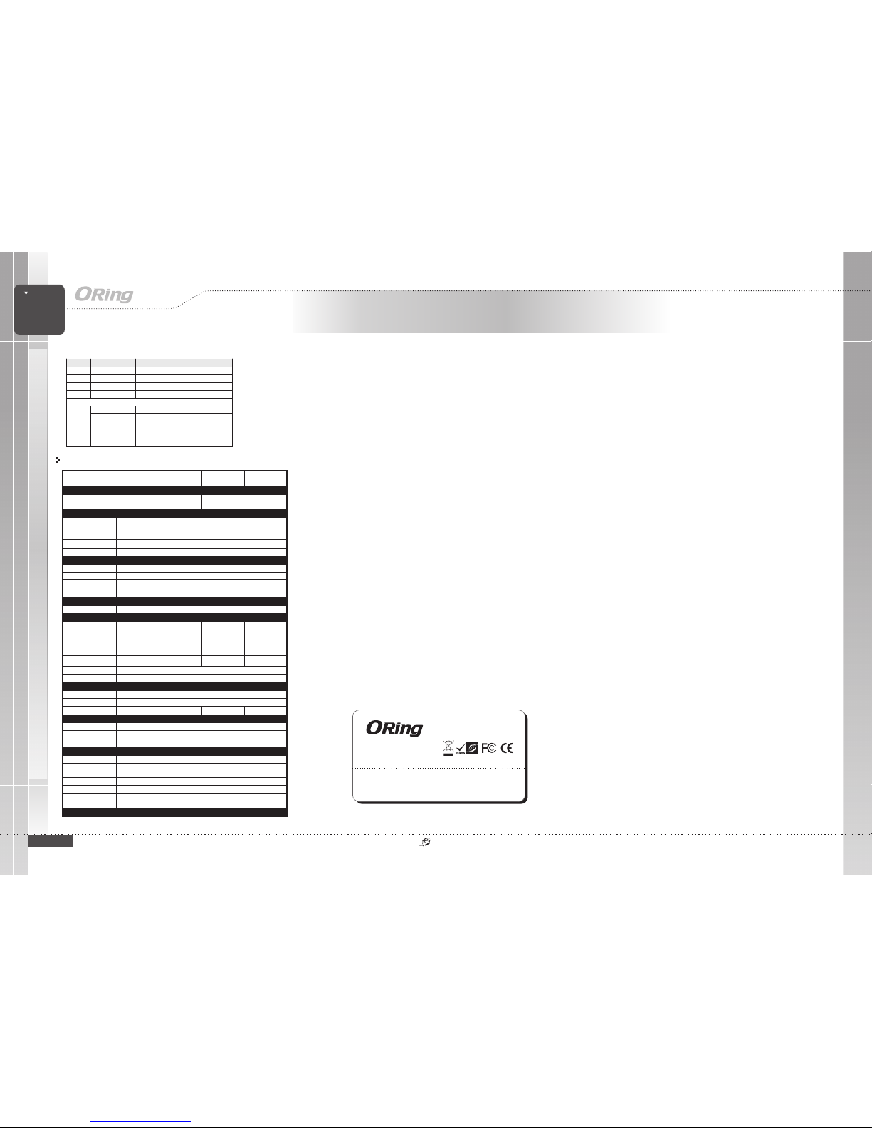
Specifications
Power
RedundantInput Power
PowerConsumption(Typ.)
DualDC inputs.
50~57VDCon 5-pin
M23connector
2.5Watts (power
consumptionof P.S.E.
isnot included)
Physical Characteristic
Enclosure
IP-40
Dimension(WxDxH)
125(W)x 65(D) x196(H) mm (4.92x 2.56 x7.66 inch.)
Weight (g)
996g
Environmental
-40to85C(-40to185F)
oo
StorageTemperature
5%to 95% Non-condensing
OperatingHumidity
Regulatory Approvals
FCCPart 15, CISPR(EN55022) class A,EN50155 (EN50121-3-2, EN55011,EN50121-4)
EMI
EN61000-4-2(ESD), EN61000-4-3 (RS),EN61000-4-4 (EFT), EN61000-4-5(Surge),
EN61000-4-6(CS), EN61000-4-8, EN61000-4-11
EMS
IEC60068-2-27
Shock
IEC60068-2-32
IEC60068-2-6
Vibration
FreeFall
Warranty
5years
LED Indicators
PowerIndicator
Green:Power LED x3
EN60950-1
Safety
FaultIndicator
Amber:IndicatePWR1orPWR2failure
10/100Base-T(X)M12 port
indicatorand PoE indicator
Topfor port Link/Actindicator. Greenfor 1Gbps link,Amber for 10Mbps link.
Middle
Bottom
Amberfor Duplex /Collision indicator
Bluefor PoE powerinjected indicator
Fault Contact
Relay
Relayoutput to carrycapacity of 3Aat 24VDC onM12 connector (5-pinM12 A-coding)
OverloadCurrent Protection
ReversePolarity Protection
Present
Present
-40to70C(-40to158F)
oo
OperatingTemperature
ORing SwitchModel
10/100Base-T(X)Ports
inM12 With P.S.E.
8xM12connector(4pinD-coding)
Physical Ports
Technology
EthernetStandards
IEEE802.3 for 10Base-T
IEEE802.3u for 100Base-TX
IEEE802.3x for Flowcontrol
IEEE802.3at compliant PoEspecification
TPS-1080-M12
8KMAC addresses
MACTable
Store-and-Forward
Processing
TPS-1080-M12-BP2
8 x M12 connector(4-pin D-coding,
bypass function included on port5~8)
1018g
LED Color Status Desc ription
Power Green On Power is on
PWR1 Green On DC power modul e 1 activated
PWR2 Green On DC power modul e 2 activated
Fault Am ber On Errors occur (power f ailure or port link d own)
10/100Base-T( X)
Green On Port running at 100Mbps
LNK/ACT
Amber On Port runni ng at 10Mbps
Duplex /
Collision
Amber On
Collision occurs
PoE Blue On Port pr oviding power to PD dev ices
TPS-1080-M12-24V
TPS-1080-M12
-BP2-24V
DualDC inputs.
24(12~57VDC) VDC on
5-pinM23 connector
DualDC inputs.
50~57VDCon 5-pin
M23connector
DualDC inputs.
24(12~57VDC) VDC on
5-pinM23 connector
2.5Watts (power
consumptionof P.S.E.
isnot included)
7.5Watts (power
consumptionof P.S.E.
isnot included)
7.5Watts (power
consumptionof P.S.E.
isnot included)
PoEOutputPower
240Watts240Watts
60Watts (12~24VDC)/
120Watts (24~57VDC)
60Watts (12~24VDC)/
120Watts (24~57VDC)
1054g 1076g
TPS-1080-M12 Series
TPS-1080-M12 Series
 Loading...