

ORiNG TGAR-1062PLUS-3GS-M12, TGAR-1062PLUS-4GS-M12, TGAR-2062PLUS-3GS-M12, TGAR-2062PLUS-4GS-M12, TGAR-1662PLUS-3GS-M12 Quick Installation Manual
...
Quick InstallationGuide
Version 1.0
Quick Installation Guide
Introduction
PRINTED ON RECYCLED PAPER
QIG
1907-2-29-TGAR+GPS-1.0
Designed forindustrial and rollingstock wireless applicationswith two LAN
ports inM12 connectors andEN50155 compliance, the
are IEEE802.11 a/b/g/nrouters capable of
providing afast and effectiveway to communicatewith the Internetover
wired orwireless LANs. Theseries includes PoE models and3G/4G models
with GPSfunctions. The seriesof devices canbe configured tooperate in 3
modes ofrouting function: dynamic/staticIP route, PPPoEauthentication,
and cellularmodem dial up.You canset up WLANenvironment to fulfill
demands ofvarious applications rapidlyby dialing upcellular modem. With
dual Ethernetports in switchmode, you canuse Daisy Chainto reduce the
usage ofEthernet switch ports.The router alsoprovides VPN capabilities
which createencrypted virtual tunnelson the Internet,allowing remote or
mobile usersto connect tothe network ofyour office.
TGAR-
1062/2062/1662+ series
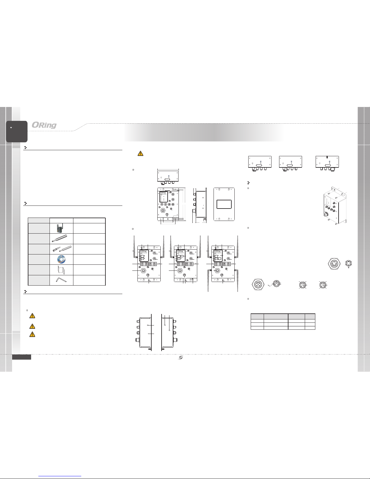
Package Contents
Installation
Wall-mount
The devicecan be fixedto the wall.Follow the stepsbelow
to installthe device onthe wall.
Hold the evice upright against the wall
Insert four screws through the large opening of
the keyhole-shaped apertures at the top and bottom of
the unit and fastenthe screw tothe wall witha screwdriver.
Slide the evice downwards and tighten the four
screws for added stability.
Step 1:
Step 2:
Step 3:dd
The devicesare shipped withthe following items.If any ofthese items is
missing ordamaged, please contactyour customer servicerepresentative for
assistance.
Preparation
Before youbegin installing thedevice, make sureyou have allof the package
contents availableand a PCwith Microsoft InternetExplorer 6.0 orlater, for
using web-basedsystem management tools.
Elevated OperatingAmbient:
ReducedAir Flow:
Mechanical Loading:
If installedin a closed environment, makesure
the operating ambient temperature is compatible with the maximum
ambient temperature (Tma) specified by the manufacturer.
Make surethe amount ofair flow requiredfor safe operation
of theequipment is notcompromised during installation.
Make surethe mounting ofthe equipment is not in a
hazardous conditiondue to unevenmechanical loading.
Safety & Warnings
For pinassignments of power,console andrelay output ports,please refer tothe following tables.
Contents
CD
3G or4G Antenna
Router
Pictures Number
1
1
QIG
1
2.4GHz/5GHz Wi-Fi
Antenna
2 (TGAR-1062+/2062+)or
4 (TGAR-1662+)
Dimension
Panel Layouts
Front Panel
Power
DO DI
ETH2
(P.O.E)
ETH1
Console
RelayOutput
1BI_DC+
2BI_DD+
3BI_DD4BI_DA5BI_DB+
6BI_DA+
7BI_DC8BI_DB-
4
5
6
7
8
21
3
V1+
V1-
V2+
V2-
RSVD
RxD
RS-232,115200bps,8,N,1
GND
TxD
N.C.
Relay
N.C.
1A@24VDC
DI1
COM
DI2
DI3DI4
GND
DO1 DO2
DO3DO4
TGAR-1062+-GPS-M12
PWR1
PWR2
(P.O.E)
ETH1
ETH2
Fault
WLAN
1
3
2
5
6
7
8
9
10
TGAR-1062+-3/4GS-M12
11
TGAR-1662+-3/4GS-M12
1. PWRstatus LED
(PW2 withPoE indicator)
2. LANport status LED
3. Faultstatus LED
4. WANstatus LED
Wireless
EN50155
ACCESS POINTROUTER
EN50155 Industrial Wireless LAN
PoE Access Point Router
Wiring
Grounding
Grounding andwire routing helplimit the effectsof noise dueto electromagnetic interference
(EMI). Runthe ground connectionfrom the groundingpin on thepower connector tothe grounding
surface priorto connecting devices.
Power portpinouts
The devicesupports two setsof power suppliesand uses theM23 5-pin
female connector on the front panel for the dual power inputs.
Insert a power cableto the powerconnector on thedevice.
Rotate theouter ring ofthe cable connectoruntil a snug fit is
achieved. Make sure the connection is tight.
Step 1:
Step 2:
V1+
V1-
V2+
V2-
Relay outputport pinouts
Relay
N.C.
1A@24VDC
DI/DO PortPinouts
DODI
DI1
COM
DI2
DI3DI4
GND
DO1 DO2
DO3DO4
Network Connection
TheAP router hastwo 10/100/1000 Base-T(X)Ethernet ports. Accordingto the linktype, theAP
router uses CAT 3,4, 5, 5e,UTP cables to connect to any other network device (PCs, servers,
evicees, routers, or hubs). Please refer to the following table for cable specifications.d
Cable Type Max. Length Connector
10Base-T Cat. 3, 4, 5 100-ohm UTP 100 m (328 f t) M12
100Base-TX Cat. 5 100-ohm UTP UTP 100 m (328 f t) M12
1000Base-T Cat. 5/Cat. 5e 100 -ohm UTP UTP 100 m ( 328 ft) M12
1 (TGAR-1062+/1662+)or
2 (TGAR-2062+)
SIMCardSlot
Cellular
ANT.
Power
DO DI
ETH2
(P.O.E)
ETH1
Console
RelayOutput
1BI_DC+
2BI_DD+
3BI_DD4BI_DA5BI_DB+
6BI_DA+
7BI_DC8BI_DB-
4
5
6
7
8
21
3
V1+
V1-
V2+
V2-
RSVD
RxD
RS-232,115200bps,8,N,1
GND
TxD
N.C.
Relay
N.C.
1A@24VDC
DI1
COM
DI2
DI3DI4
GND
DO1 DO2
DO3DO4
TGAR+GPSSeries
PWR1
PWR2
(P.O.E)
ETH1
ETH2
Fault
WAN
WLAN1
WLAN2
R2.5
168.4
7.50
R4.0
86.0
56.5
3.50
WIFI1
ANT.1
WIFI2
ANT.1
Reset
196.1
125.6
15.0
6519.1
12.5
WAN
TGAR-2062+-3/4GS-M12
5. WLANstatus LED
6.Relayoutputport
7. Consoleport
8. EthernetLAN ports
(ETH2withPoE)
4
1312
Power
DO DI
ETH2
(P.O.E)
ETH1
Console
RelayOutput
1BI_DC+
2BI_DD+
3BI_DD4BI_DA5BI_DB+
6BI_DA+
7BI_DC8BI_DB-
4
5
6
7
8
21
3
V1+
V1-
V2+
V2-
RSVD
RxD
RS-232,115200bps,8,N,1
GND
TxD
N.C.
Relay
N.C.
1A@24VDC
DI1
COM
DI2
DI3DI4
GND
DO1 DO2
DO3DO4
TGAR-2062+-GPS-M12
PWR1
PWR2
(P.O.E)
ETH1
ETH2
Fault
WLAN
1
3
2
5
6
7
8
9
10
11
WAN1
4
1312
WAN2
Power
DO DI
ETH2
(P.O.E)
ETH1
Console
RelayOutput
1BI_DC+
2BI_DD+
3BI_DD4BI_DA5BI_DB+
6BI_DA+
7BI_DC8BI_DB-
4
5
6
7
8
21
3
V1+
V1-
V2+
V2-
RSVD
RxD
RS-232,115200bps,8,N,1
GND
TxD
N.C.
Relay
N.C.
1A@24VDC
DI1
COM
DI2
DI3DI4
GND
DO1 DO2
DO3DO4
TGAR-1662+-GPS-M12
PWR1
PWR2
(P.O.E)
ETH1
ETH2
Fault
WLAN1
1
3
2
5
6
7
8
9
10
11
WAN
4
1312
WLAN2
WIFI
ANT.1
Reset
1
2
1. 3G/4GAntenna connector
2. Resetbutton
3. GPSantenna connector
Side Panel
Allen Key
1
PoE
Circuit Overloading:Consideration should begiven to theconnection of theequipment to
the supplycircuit and theeffect that overloadingof the circuitsmight have onovercurrent
protection andsupply wiring.Appropriate consideration ofequipment nameplate ratings
should beused when addressingthis concern.
9. DI/DOports
10. Powerconnector
11. 2.4/5GHzWi-Fi antenna
12. Cellularantenna connector
13. SIMcard slot
14. Ground
WIFI
ANT.1
GPS
ANT
1 3
Bottom Panel
TGAR-2062+-3/4GS-M12
SIMCardSlot2
Cellular2
ANT.
TopPanel
SIMCardSlot
Cellular
ANT.
SIMCardSlot
Cellular
ANT.
TGAR-1062+/1662+
-3/4GS-M12
TGAR-2062+-3/4GS-M12
TGAR+ GPS Series
TGAR+ GPS Series
14
1413 12 14

QIG
Quick InstallationGuide
PRINTED ON RECYCLED PAPER
Quick Installation Guide
Version 1.0
QIG
Configurations
After installingthe router and connecting cables, start the evice by
turning onpower. Thegreen power LEDshould turn on. Please refer to
the following tablet for LED indication.
d
1. Launchthe Internet Explorerand type inIP address ofthe device.The default static
IP addressis 192.168.10.1
Specifications
Follow thesteps below tolog in andaccess the system:
2. Login with defaultuser name andpassword (both are ).admin
3.After logging in,you should seethe following screen.For more informationon
configurations, pleaserefer to theuser manual. Forinformation on operatingthe device
using ORing’sOpen-Vision management utility, pleasego to ORingwebsite.
Power
RedundantInput Power
DualPower Inputs. 12~48VDC on M23connector (24 VDCTyp.)
Physical Characteristic
Enclosure
IP-40
Dimension(WxDxH)
125(W)x 65(D) x196(H) mm (4.92x 2.56 x7.72 inch.)
Weight (g)
Environmental
-40to85C(-40to185F)
oo
StorageTemperature
5%to 95% Non-condensing
OperatingHumidity
Regulatory Approvals
FCCPart 15, CISPR(EN55022) class A,EN50155 (EN50121-3-2, EN55011,EN50121-4)
EMI
EN61000-4-2(ESD), EN61000-4-3 (RS),EN61000-4-4 (EFT), EN61000-4-5 (Surge),
EN61000-4-6(CS), EN61000-4-8, EN61000-4-11
EMS
IEC60068-2-27,EN61373
Shock
IEC60068-2-32
IEC60068-2-6
Vibration
Free Fall
Warranty
5years
Frequency Band
TransmissionRate
Encryption Security
WEP: (64-bit,128-bit keysupported)
WPA/WPA2:(WEP and AESencryption)
WPA-PSK(256-bit key pre-sharedkey supported)
802.1X Authenticationsupported
TKIP encryption
802.11i
Wireless Security
SSIDbroadcast disable
TransmitPower
ReceiverSenstivity
Protocol Support
Protocol
ARP,BOOTP,DHCP,DNS,HTTP,IP,ICMP,SNTP,TCP,UDP,RADIUS,SNMP,PPPoE,STP(IEEE802.1D)
EN60950-1
Safety
-25to70C(-13to158F)
oo
OperatingTemperature
ORing WLANAccess
Point Model
10/100/1000Base-T(X)Ports in
M12 AutoMDI/MDIX
(8-pin A-coding)
2 (PoEP.D. present atETH2 Fully compliantwith IEEE 802.3af)
Physical Ports
Technology
Modulation
WLAN Interface
Antenna andConnector
4 xExternal reverseSMA type
antenna connector
RadioFrequency Type DSSS,OFDM
TGAR-1062+
-3GS-M12
IEEE802.11b:CCK, DQPSK, DBPSK
IEEE802.11g:OFDM with BPSK,QPSK, 16QAM, 64QAM
IEEE802.11a:OFDM with BPSK,QPSK, 16QAM, 64QAM
IEEE802.11n:BPSK, QPSK, 16-QAM,64-QAM
America /FCC : 2.412~2.462 GHz (11channels)
5.180~5.240 GHz& 5.745~5.825 GHz(9channels)
EuropeCE/ETSI:2.412~2.472Ghz(13channels)
5.180~5.240 Ghz(4 channels)
802.11a: -68dBm±2.0dB@ 54 Mbps
802.11b: -82dBm dB @ 11Mbps
802.11g: -68dBm dB @ 54Mbps
802.11gn HT20:-64dBm
±2.0
±2.0
±2.0dB @150Mbps
802.11gn HT40:-60dBm±2.0dB @300Mbps
802.11an HT20:-64dBm±2.0dB @150Mbps
802.11an HT40:-60dBm±2.0dB @300Mbps
985g
IEEE801.11b: 1/2/ 5.5/ 11Mbps
IEEE801.11a/g: 6/9/ 12/ 18/24/ 36/ 48/54 Mbps
IEEE802.11n: upto 300Mbps
802.11a: 12dBm dBm
802.11b: 18dBm dBm
802.11g: 15dBm dBm
802.11gn HT20:13dBm m@150Mbps
802.11gn HT40:12dBm m@300Mbps
802.11an HT20:12dBm m@150Mbps
802.11an HT40:12dBm dBm@300Mbps
±1.5
±1.5
±1.5
±1.5 dB
±1.5 dB
±1.5 dB
±1.5
DI/DOportinM12
(5-pin A-coding)
RS-232ConsoleportinM12
(5-pin A-coding)
RelayportinM12
(5-pin A-coding)
2(DIx4andDOx4)
115200, 8,N ,1
1A@24VDC
2 xExternal reverseSMA type antennaconnector
Resetting
Torestore the device configurations back to the factory defaults, press the button for a
few seconds. Once the power indicator starts to flash, release the button. The device will
then reboot and return to factory defaults.
Reset
TGAR-1062+
-4GS-M12
TGAR-2062+
-3GS-M12
TGAR-2062+
-4GS-M12
TGAR-1662+
-3GS-M12
TGAR-1662+
-4GS-M12
SIMCardSlot
1 21
Cellular Interface
Cellular Standard
GSM/GPRS/
EGPRS/EDGE /
WCDMA/HSDPA
/HSUPA
GSM/GPRS/
EGPRS/EDGE/
WCDMA/HSDPA
/HSUPA /HSPA+
/LTE
GSM/GPRS/
EGPRS/EDGE/
WCDMA/HSDPA
/HSUPA
GSM/GPRS/
EGPRS/EDGE/
WCDMA/ HSDPA
/HSUPA /HSPA+
/LTE
GSM/GPRS/
EGPRS/EDGE /
WCDMA/ HSDPA
/HSUPA
GSM/ GPRS/
EGPRS/EDGE/
WCDMA/HSDPA
/HSUPA /HSPA+
/LTE
Antenna Connector
1x Reverse
SMAFemale
Dual-band:
HSUPA1900/
2100MHZ
Quad-band:
GSM/GPRS/
EDGE850/900/
1800/1900Hz
WCDMA/HSDPA
850/900/1900/
2100MHz
Band Option
America(US)
Europe(EU)
LTE:700/1700/
2100MHZ
UMTS/HSDPA/
HSUPA/HSPA+/
DC-HSPA+:800
/850/1900/2100
MHZ
GSM/GPRS/
EDGE:850/900/
1800/1900MHz
LTE:800/900/
1900/2100/2600
MHZ
UMTS/HSDPA/
HSUPA/HSPA+/
DC-HSPA+:900
/2100MHZ
GSM/GPRS/
EDGE:900/1800
/1900MHZ
Dual-band:
HSUPA1900/
2100MHZ
Quad-band:
GSM/GPRS/
EDGE850/900/
1800/1900Hz
WCDMA/HSDPA
850/900/1900/
2100MHz
America(US)
Europe(EU)
LTE:700/1700/
2100MHZ
UMTS/HSDPA/
HSUPA/HSPA+/
DC-HSPA+:800
/850/1900/2100
MHZ
GSM/GPRS/
EDGE:850/900/
1800/1900MHz
LTE:800/900/
1900/2100/
2600MHZ
UMTS/HSDPA/
HSUPA/HSPA+/
DC-HSPA+:900
/2100MHZ
GSM/GPRS/
EDGE:900/1800
/1900MHZ
Fault Contact
Relay
Relayoutput to carrycapacity of 1Aat 24VDC
PowerConsumption(Typ.)
9Watts 15Watts9.5Watts 13Watts 14Watts13Watts
OverloadCurrent Protection
Present
ReversePolarity Protection
Present
968g 1030 g 1033 g
1114g1098g
1x Reverse
SMAFemale
2x Reverse
SMAFemale
M12/8P PinDefinition
PIN Definition
1BI_DC+
2BI_DD+
3BI_DD-
4BI_DA-
5BI_DB+
6BI_DA+
7BI_DC-
8BI_DB-
Console PortPin Definition
4
5
6
7
8
21
3
RSVD
RxD
RS-232,115200bps, 8,N, 1
GND
TxD
N.C.
LED Color Status Descri ption
PWR1 G reen On DC power 1 activ ated.
PWR2 (Po E) Green On
DC power 2 ac tivated or PoE enabled (when
device is not connect ed to power suppl y)
On Port is linked
ETH1 G reen
Blinking Datatransmitted.
On Port is linked
ETH2 G reen
Blinking Datatransmitted.
On WLAN isactivated
WLAN 1 (2) Green
Blinking Transmitting data
WAN1 ( 2 ) Gr een On Modem is connec ted
Fault Red On Error occurs (power fa ils or port disconnec ted)
Wireless
EN50155
ACCESS POINTROUTER
EN50155 Industrial Wireless LAN
PoE Access Point Router
TGAR+ GPS Series
TGAR+ GPS Series
PoE
GPS
Antenna andConnector
Frequency 1575.42MHz
1 xExternal SMA antenna
connector
1 xExternal SMA antenna
connector
1 xExternal SMA antenna
connector
ORing IndustrialNetworking Corp.
Copyright© 2014 ORing
Allrights reserved.
TEL:+886-2-2218-1066
FAX:+886-2-2218-1014
Website:www.oring-networking.com
E-mail:support@oring-networking.com
1x SMA Female 2x SMA Female 1 x SMAFemale
 Loading...