

ORiNG TGAR-1062-M12-3G, TGAR-2062-M12-3G, TGAR-1662-M12-3G, TGAR-1662-M12-4G, TGAR-1062-M12-4G User Manual
TTGGAARR--11006622//22006622//11666622 SSeerriieess
IIEEEEEE 880022..1111 aa//bb//gg//nn AAcccceessss PPooiinntt RRoouutteerr
UUsseerr M
Maannuuaall
VVeerrssiioonn 11..00
FFeebb,, 22001144
wwwwww..oorriinngg--nneettwwoorrkkiinngg..ccoomm

TGAR-1062/2062/1662 Series User Manual
ORing Industrial Networking Corp. 1
COPYRIGHT NOTICE
Copyright © 2014 ORing Industrial Networking Corp.
All rights reserved.
No part of this publication may be reproduced in any form without the prior written consent of
ORing Industrial Networking Corp.
TRADEMARKS
is a registered trademark of ORing Industrial Networking Corp.
All other trademarks belong to their respective owners.
REGULATORY COMPLIANCE STATEMENT
Product(s) associated with this publication complies/comply with all applicable regulations.
Please refer to the Technical Specifications section for more details.
WARRANTY
ORing warrants that all ORing products are free from defects in material and workmanship for a
specified warranty period from the invoice date (5 years for most products). ORing will repair or
replace products found by ORing to be defective within this warranty period, with shipment
expenses apportioned by ORing and the distributor. This warranty does not cover product
modifications or repairs done by persons other than ORing-approved personnel, and this
warranty does not apply to ORing products that are misused, abused, improperly installed, or
damaged by accidents.
Please refer to the Technical Specifications section for the actual warranty period(s) of the
product(s) associated with this publication.
DISCLAIMER
Information in this publication is intended to be accurate. ORing shall not be responsible for its
use or infringements on third-parties as a result of its use. There may occasionally be
unintentional errors on this publication. ORing reserves the right to revise the contents of this
publication without notice.
CONTACT INFORMATION
ORing Industrial Networking Corp.
3F., No.542-2, JhongJheng Rd., Sindian District, New Taipei City 23148, Taiwan (R.O.C.)
Tel: +886-2-2218-1066 // Fax: +886-2-2218-1014
Website: www.oring-networking.com
Technical Support
E-mail: support@oring-networking.com
Sales Contact
E-mail: sales@oring-networking.com (Headquarters)
sales@oring-networking.com.cn (China)

TGAR-1062/2062/1662 Series User Manual
ORing Industrial Networking Corp. 2
Tables of Content
Getting Started ............................................................................................... 1
1.1 About TGAR-1062/2062/1662 Series ...................................................................... 1
1.2 Software Features .................................................................................................. 1
1.3 Hardware Features ................................................................................................. 2
2.1 Front Panel ............................................................................................................ 3
2.1.1 Ports and Connectors ......................................................................................... 3
2.1.2 Front Panel LEDs ............................................................................................... 5
2.2 Side Panel.............................................................................................................. 5
2.2 Top Panel ................................ ................................................................ ............... 6
2.3 Bottom Panel.......................................................................................................... 7
Hardware Installation .................................................................................... 8
3.1 Wall Mounting Installation ....................................................................................... 8
3.2 Wiring................................................................................................................... 11
3.2.1 Grounding ............................................................................................................ 11
3.2.2 Fault Relay ........................................................................................................... 11
3.2.3 Redundant Power Inputs ...................................................................................... 12
Cables and Antenna .................................................................................... 13
4.1 Ethernet Pin Definition .......................................................................................... 13
4.2 Console Port Pin Definition ................................................................................... 13
4.3 DI/DO ................................................................................................................... 14
4.4 Wireless Antenna ................................................................................................. 14
4.5 Cellular Antenna ................................................................................................... 15
Management ................................................................................................ 16
5.1 Network Connection ............................................................................................. 16
5.2 Configuration ........................................................................................................ 17
5.2.1 Basic Setting .................................................................................................... 17
WAN......................................................................................................................... 18
LAN .......................................................................................................................... 22
DHCP ....................................................................................................................... 22
Wireless AP .............................................................................................................. 24
DDNS ....................................................................................................................... 30
Date & Time ............................................................................................................. 30
5.2.2 Networking Setting ........................................................................................... 31
Wireless Setting – Advanced Setting......................................................................... 31
Wireless Setting – MAC Filter ................................................................................... 33
NAT Setting - Virtual Server ...................................................................................... 34
NAT Setting – DMZ ................................................................................................... 35
NAT Setting – UPnP ................................................................................................. 35

TGAR-1062/2062/1662 Series User Manual
ORing Industrial Networking Corp. 3
Firewall Setting – IP Filter ................................................................ ......................... 36
Firewall Setting – MAC Filter..................................................................................... 37
Vpn Setting – Open Vpn ........................................................................................... 38
Vpn Setting – PPTP VPN ................................................................ .......................... 40
Vpn Setting – PPTP Client ........................................................................................ 42
VRRP ....................................................................................................................... 43
Routing Protocol – Routing Setting ........................................................................... 45
5.2.3 System Tools .................................................................................................... 48
Login Setting ............................................................................................................ 48
Router Restart .......................................................................................................... 48
Firmware Upgrade .................................................................................................... 49
Save/Restore Configurations .................................................................................... 49
Miscellaneous........................................................................................................... 50
Event Warning .......................................................................................................... 50
E-mail ....................................................................................................................... 52
DIDO ........................................................................................................................ 54
5.2.4 System Status .................................................................................................. 55
System Info .............................................................................................................. 55
System Log .............................................................................................................. 55
Traffic Statistics ........................................................................................................ 55
Wireless Link List...................................................................................................... 56
Technical Specifications ............................................................................. 57
Compliance ............................................................................................ 62
TGAR-1062/2062/1662 Series User Manual
ORing Industrial Networking Corp. 1
Getting Started
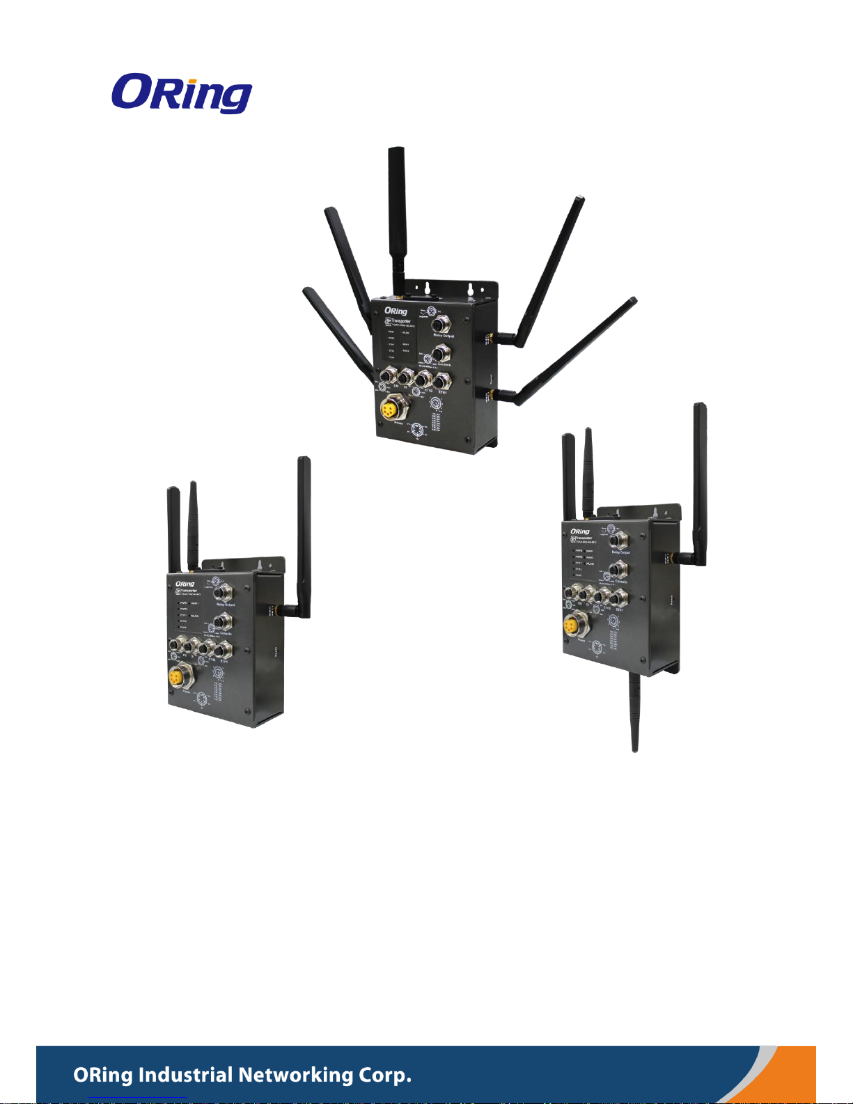
1.1 About TGAR-1062/2062/1662 Series
Designed for industrial and rolling stock wireless
applications with two LAN ports in M12 connectors and
EN50155 compliance, the ORing TGAR-1062/2062/1662
series are IEEE802.11 a/b/g/n routers capable of providing
a fast and effective way to communicate with the Internet
over wired or wireless LANs. Consisting of 3G and 4G
models, the series of devices can be configured to operate
in 3 modes of routing function: dynamic/static IP route,
PPPoE authentication, and cellular modem dial up. Users
can set up WLAN environment to fulfill demands of various applications rapidly by dialing up
cellular modem. With dual Ethernet ports in switch mode, you can use Daisy Chain to reduce
the usage of Ethernet switch ports. The router also provides VPN capabilities which create
encrypted virtual tunnels on the Internet, allowing remote or mobile users to connect to the
network of your office.
1.2 Software Features
High-speed air connectivity for up to 300Mbps
High security with support for WEP/WPA/WPA-PSK(TKIP,AES)/
WPA2/WPA2-PSK(TKIP,AES)/802.1X authentication
Secure management by HTTPs
Various kinds of WAN connections supported, including dynamic/static IP, PPPoE, and
modem dial up
Configurable IP tables to prevent unauthorized access
Supports VPN for secure network connection (Open VPN , PPTP VPN)
Supports NAT setting (virtual server , port trigger , DMZ , UPnP)
Supports DHCP forwarding through PPTP
3.5G HSDPA modem dial up (3G models)
4G LTE modem dial up (4G models)
Supports redundant mode (Recovery time < 10ms) and switch mode in M12 connector
(A-coding)
Wireless connection status monitoring
Event warning by Syslog, e-mail, SNMP trap, and relay output

TGAR-1062/2062/1662 Series User Manual
ORing Industrial Networking Corp. 2
1.3 Hardware Features
2 x 10/100/1000 Base-T(X) Ethernet ports in M12 connectors
2 x WLAN antenna connectors (TGAR-1062/2062 series) or 4 x WLAN antenna connectors
(TGAR-1662 series)
1 x cellular antenna connectors (TGAR-1062/1662 series) or 2 x cellular antenna
connectors (TGAR-2062 series)
EN50155 compliance
Redundant power inputs: 12~48 VDC
Casing: IP-40
Dimensions: 125.6mm (W) x 65mm (D) x 196.1mm (H) (4.94 x 2.55 x 7.72 inch)
Operating temperature: -25 to 70°C
Storage temperature: -40 to 85°C
Operating humidity: 5% to 95%, non-condensing
Wall mounting enabled

TGAR-1062/2062/1662 Series User Manual
ORing Industrial Networking Corp. 3
Hardware Overview
2.1 Front Panel
2.1.1 Ports and Connectors
The series is equipped with the following ports and features on the front panel.
Port
Description
10/100/1000 Base-T(X) Ethernet ports
with M12 connectors (D-coding)
2 x 10/100/1000 Base-T(X) ports supporting
auto-negotiation.
Relay output with M12 (A-coding)
connector
1 x relay output to carry capacity of 1A at 24VDC
M23 power connector with redundant
power inputs
Dual power inputs for 12~48 VDC
DIDO with M12 connector (D-coding)
4 x digital input / 4 x digital output
TGAR-1062 Series

TGAR-1062/2062/1662 Series User Manual
ORing Industrial Networking Corp. 4
TGAR-2062 Series
TGAR-1662 Series
TGAR-1062/2062/1662 Series User Manual
ORing Industrial Networking Corp. 5
2.1.2 Front Panel LEDs
LED
Color
Status
Description
PWR1
Green
On
DC power 1 activated.
PWR2
Green
On
DC power 2 activated.
ETH1
Green
On
Port is linked
Blinking
Data transmitted.
ETH2
Green
On
Port is linked
Green
Blinking
Transmitting data
On
Port is linked
WLAN 1 (2)
Green
On
WLAN is activated
Blinking
Transmitting data
WAN1 (2)
Green
On
Modem is connected
Fault
Red
On
Error occurs (power fails or port disconnected)
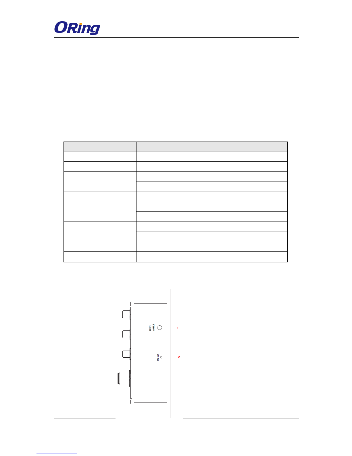
2.2 Side Panel
1. Power status LED
2. LAN port status LED
3. Fault status LED
4. WAN status LED
5. WLAN status LED
6. Relay output port
1. Antenna connector
2. Reset button
7. Console & Backup unit port
8. Ethernet LAN ports
9. DI/DO ports
10. Power connector
11. 2.4/5GHz antenna
12. Cellular antenna connector
13. SIM card slot
TGAR-1062/2062/1662 Series User Manual
ORing Industrial Networking Corp. 6
Note: to restore the device configurations back to the factory defaults, press the Reset button
for a few seconds. Once the power indicator starts to flash, release the button. The device will
then reboot and return to factory defaults.
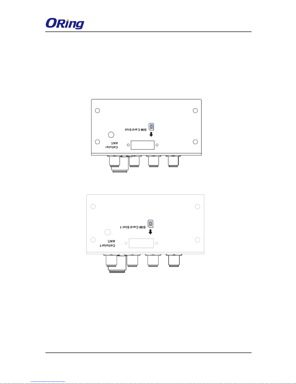
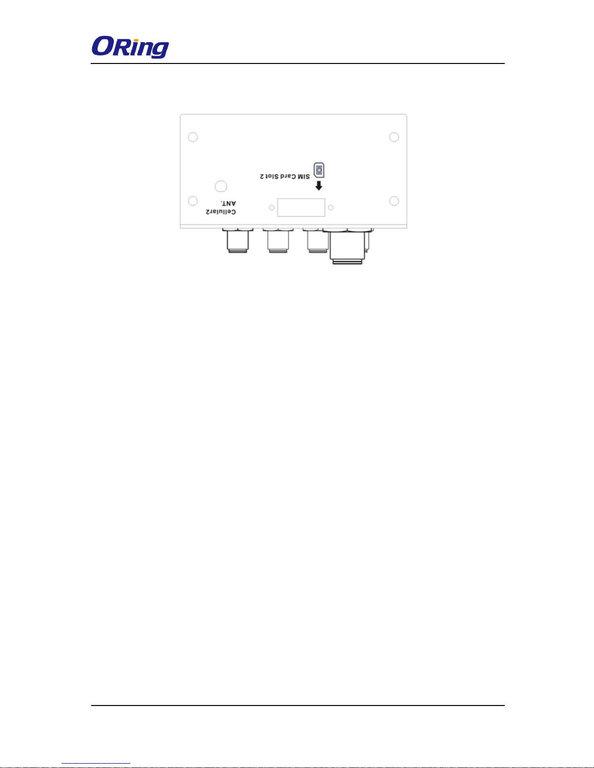
2.2 Top Panel
On the top panel sits a SIM card slot and a cellular antenna connector, as show as below.
TGAR-1062/1662 Series
TGAR-2062 Series
TGAR-1062/2062/1662 Series User Manual
ORing Industrial Networking Corp. 7
2.3 Bottom Panel
TGAR-2062 Series
TGAR-1062/2062/1662 Series User Manual
ORing Industrial Networking Corp. 8
Hardware Installation
Elevated Operating Ambient: If installed in a closed environment, make sure the
operating ambient temperature is compatible with the maximum ambient
temperature (Tma) specified by the manufacturer.
Reduced Air Flow: Make sure the amount of air flow required for safe operation of
the equipment is not compromised during installation.
Mechanical Loading: Make sure the mounting of the equipment is not in a
hazardous condition due to uneven mechanical loading.
Circuit Overloading: Consideration should be given to the connection of the
equipment to the supply circuit and the effect that overloading of the circuits might
have on overcurrent protection and supply wiring. Appropriate consideration of
equipment nameplate ratings should be used when addressing this concern.
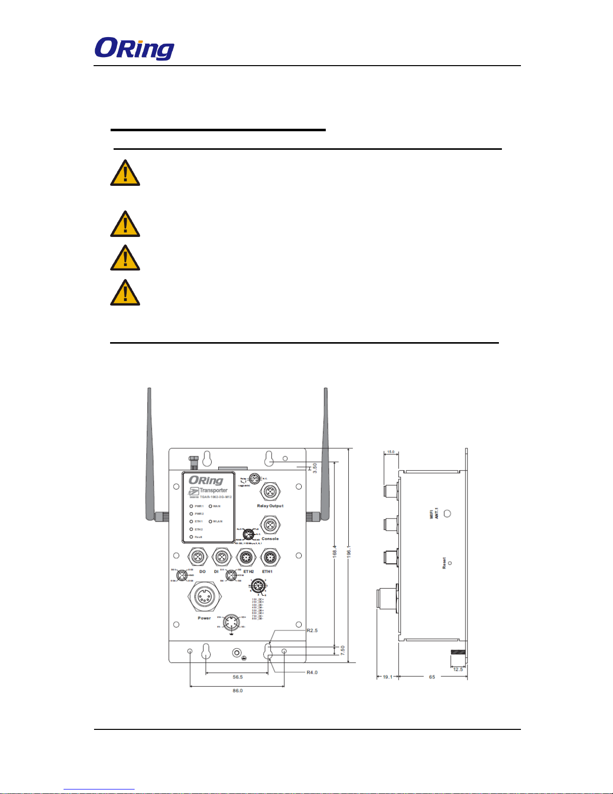
3.1 Wall Mounting Installation
TGAR-1062 Series Wall-mount Kit Measurement

TGAR-1062/2062/1662 Series User Manual
ORing Industrial Networking Corp. 9
TGAR-2062 Series Wall-mount Kit Measurement
TGAR-1062/2062/1662 Series User Manual
ORing Industrial Networking Corp. 10
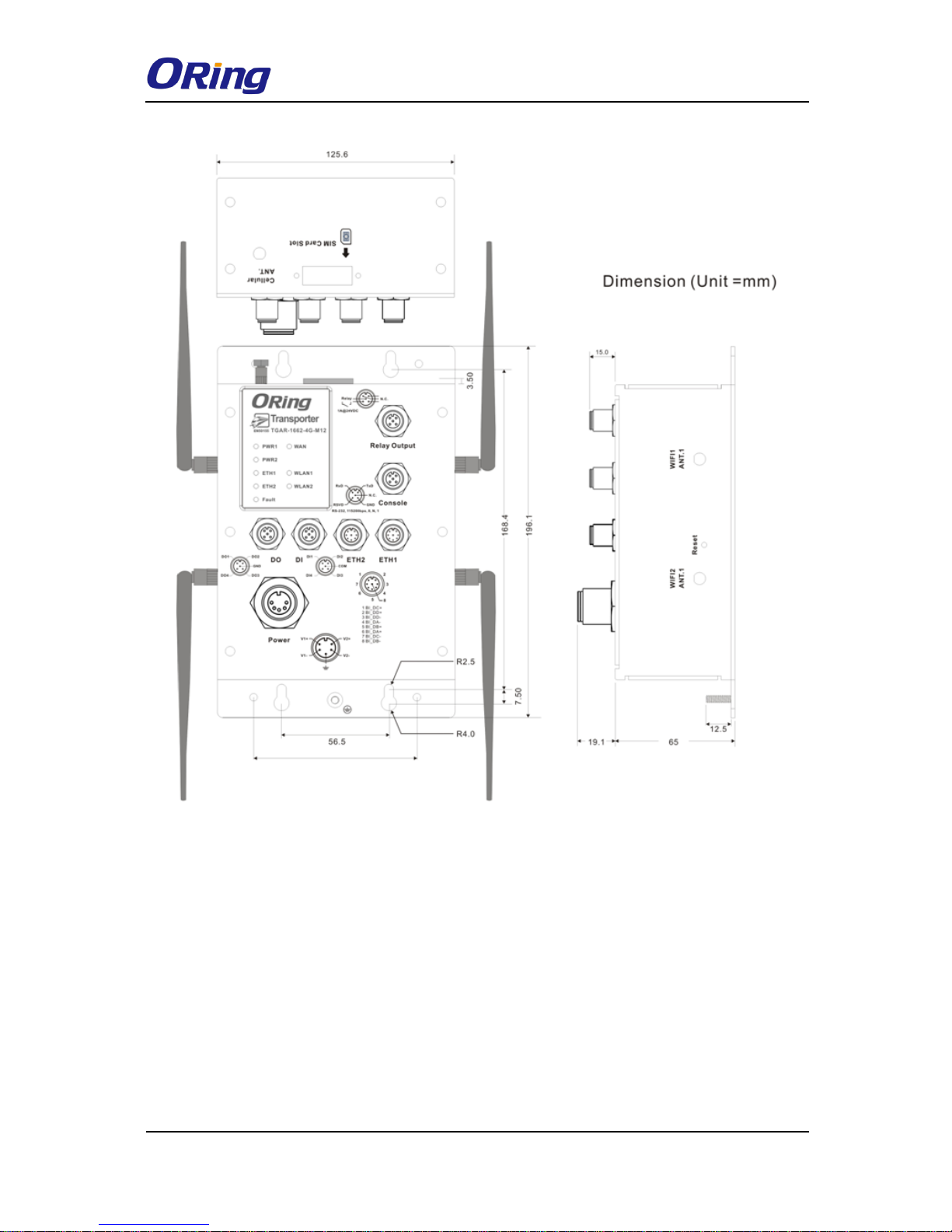
TGAR-1662 Series Wall-mount Kit Measurement
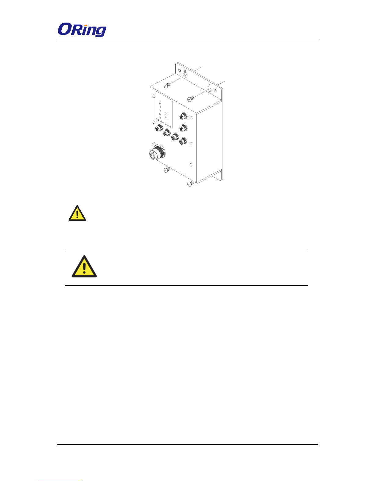
The device can be fixed to the wall. Follow the steps below to install the device on the wall.
Step 1: Hold the router upright against the wall
Step 2: Insert four screws through the large opening of the keyhole-shaped apertures at the
top and bottom of the unit and fasten the screw to the wall with a screwdriver.
Step 3: Slide the router downwards and tighten the four screws for added stability.
TGAR-1062/2062/1662 Series User Manual
ORing Industrial Networking Corp. 11
Instead of screwing the screws in all the way, it is advised to leave a space of
about 2mm to allow room for sliding the switch between the wall and the screws.
3.2 Wiring
WARNING
Be sure to switch off the power and make sure the area is not hazardous
before disconnecting modules or wires. The devices may only be connected to
the supply voltage shown on the type plate.
3.2.1 Grounding
Grounding and wire routing help limit the effects of noise due to electromagnetic interference
(EMI). Run the ground connection from the ground pin on the power connector to the
grounding surface prior to connecting devices.
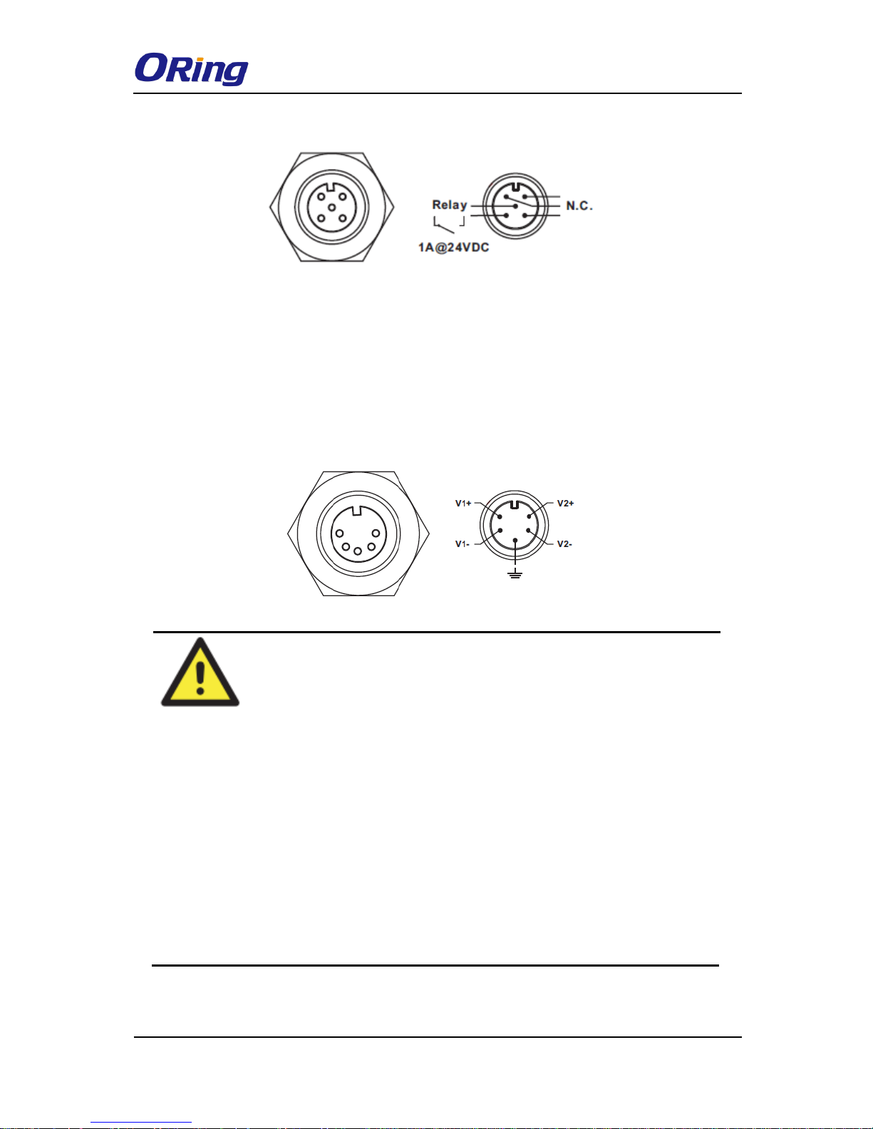
3.2.2 Fault Relay
The router uses a M12 A-coded 5-pin male connector on the front panel for relay output. Use
a power cord with an M12 A-coded 5-pin female connector to connect the relay. The relay
contacts will detect user-configured events and form an open circuit when an event is
triggered.
TGAR-1062/2062/1662 Series User Manual
ORing Industrial Networking Corp. 12
3.2.3 Redundant Power Inputs
The device supports two sets of power supplies and uses the M23 5-pin female connector on
the front panel for the dual power inputs.
Step 1: Insert a power cable to the power connector on the device.
Step 2: Rotate the outer ring of the cable connector until a snug fit is achieved. Make sure
the connection is tight
ATTENTION
1. Be sure to disconnect the power cord before installing and/or wiring your
routers.
2. Calculate the maximum possible current in each power wire and
common wire. Observe all electrical codes dictating the maximum
current allowable for each wire size.
3. If the current goes above the maximum ratings, the wiring could
overheat, causing serious damage to your equipment.
4. Use separate paths to route wiring for power and devices. If power
wiring and device wiring paths must cross, make sure the wires are
perpendicular at the intersection point.
5. Do not run signal or communications wiring and power wiring through
the same wire conduit. To avoid interference, wires with different signal
characteristics should be routed separately.
6. You can use the type of signal transmitted through a wire to determine
which wires should be kept separate. The rule of thumb is that wiring
sharing similar electrical characteristics can be bundled together
7. You should separate input wiring from output wiring
8. It is advised to label the wiring to all devices in the system
TGAR-1062/2062/1662 Series User Manual
ORing Industrial Networking Corp. 13
Cables and Antenna
4.1 Ethernet Pin Definition
The routers have two 10/100/1000 Base-T(X) Ethernet ports. According to the link type, the
AP uses CAT 3, 4, 5, 5e, UTP cables to connect to any other network device (PCs, servers,
switches, routers, or hubs). Please refer to the following table for cable specifications.
Cable
Type
Max. Length
Connector
10Base-T
Cat. 3, 4, 5 100-ohm
UTP 100 m (328 ft)
RJ45
100Base-T(X)
Cat. 5 100-ohm UTP
UTP 100 m (328 ft)
RJ45
1000Base-T(X)
Cat 5e,6
UTP 100 m (328 ft)
RJ45
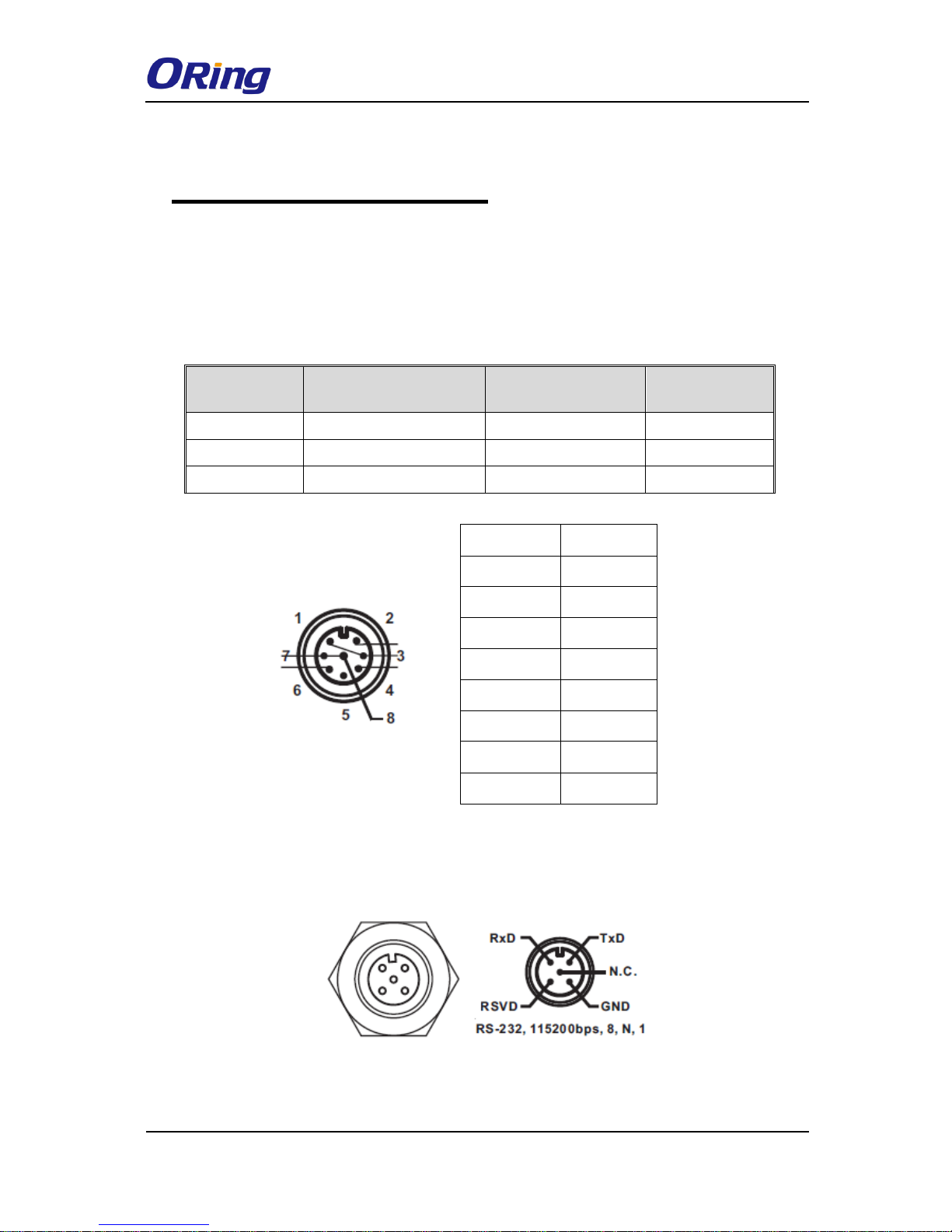
4.2 Console Port Pin Definition
PIN
Definition
1
BI_DC+
2
BI_DD+
3
BI_DD-
4
BI_DA-
5
BI_DB+
6
BI_DA+
7
BI_DC-
8
BI_DB-
TGAR-1062/2062/1662 Series User Manual
ORing Industrial Networking Corp. 14
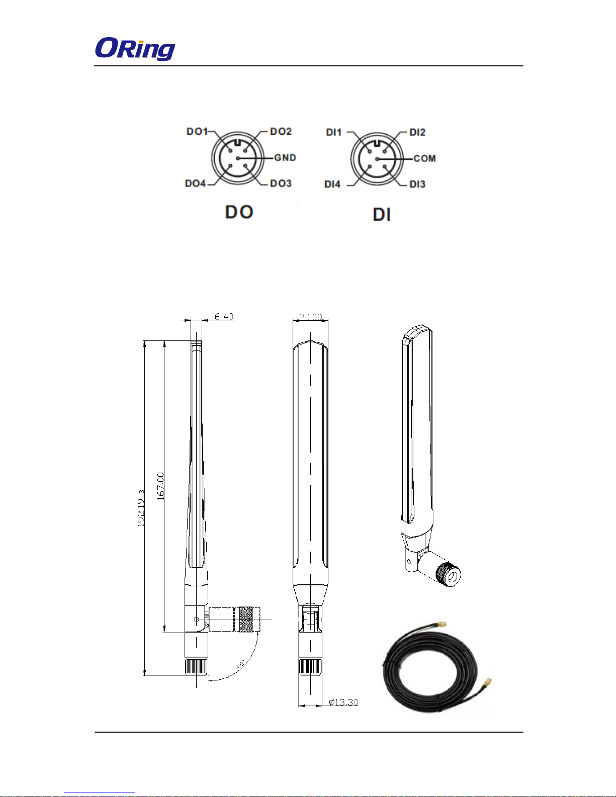
4.3 DI/DO
4.4 Wireless Antenna
The series uses 2.4GHz/5GHz antennas with reversed SMA connectors. You can also use
external RF cables and antennas with the connectors.
TGAR-1062/2062/1662 Series User Manual
ORing Industrial Networking Corp. 15
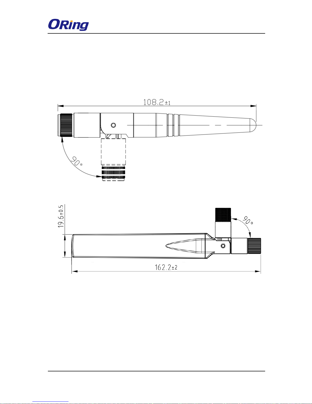
4.5 Cellular Antenna
The series are packed with one or two 3G and 4G antennas. External RF cables and antennas
can also be used with the connector.
3G Cellular Antenna
4G LTE Antenna
TGAR-1062/2062/1662 Series User Manual
ORing Industrial Networking Corp. 16
Management
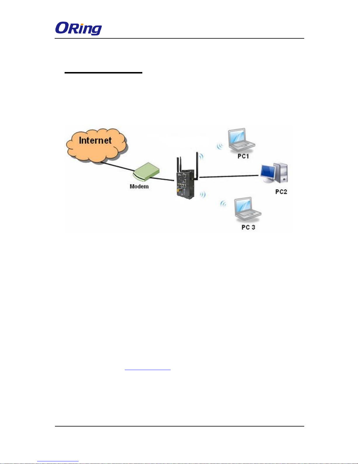
5.1 Network Connection
Before installing the router, you need to be able to access the router via a computer equipped
with an Ethernet card or wireless LAN interface. To simplify the connection, it is
recommended to use an Ethernet card to connect to a LAN.
Network Connection of the Router
Before installing the router, you need a computer equipped with an Ethernet card or wireless
LAN interface. To simplify the connection, it is recommended to use an Ethernet card to
connect to a LAN. Follow the steps below to install and connect the router to PCs:
Step 1: Select a power source. The router can be powered by +12~48V DC power input, or
via a PoE (Power over Ethernet) PSE Ethernet switch.
Step 2: Connect a computer to the router. Use either a straight-through Ethernet cable or
cross-over cable to connect the ETH1 port of the router to a computer. Once the LED of the
LAN port lights up, which indicates the connection is established, the computer will initiate a
DHCP request to retrieve an IP address from the AP router.
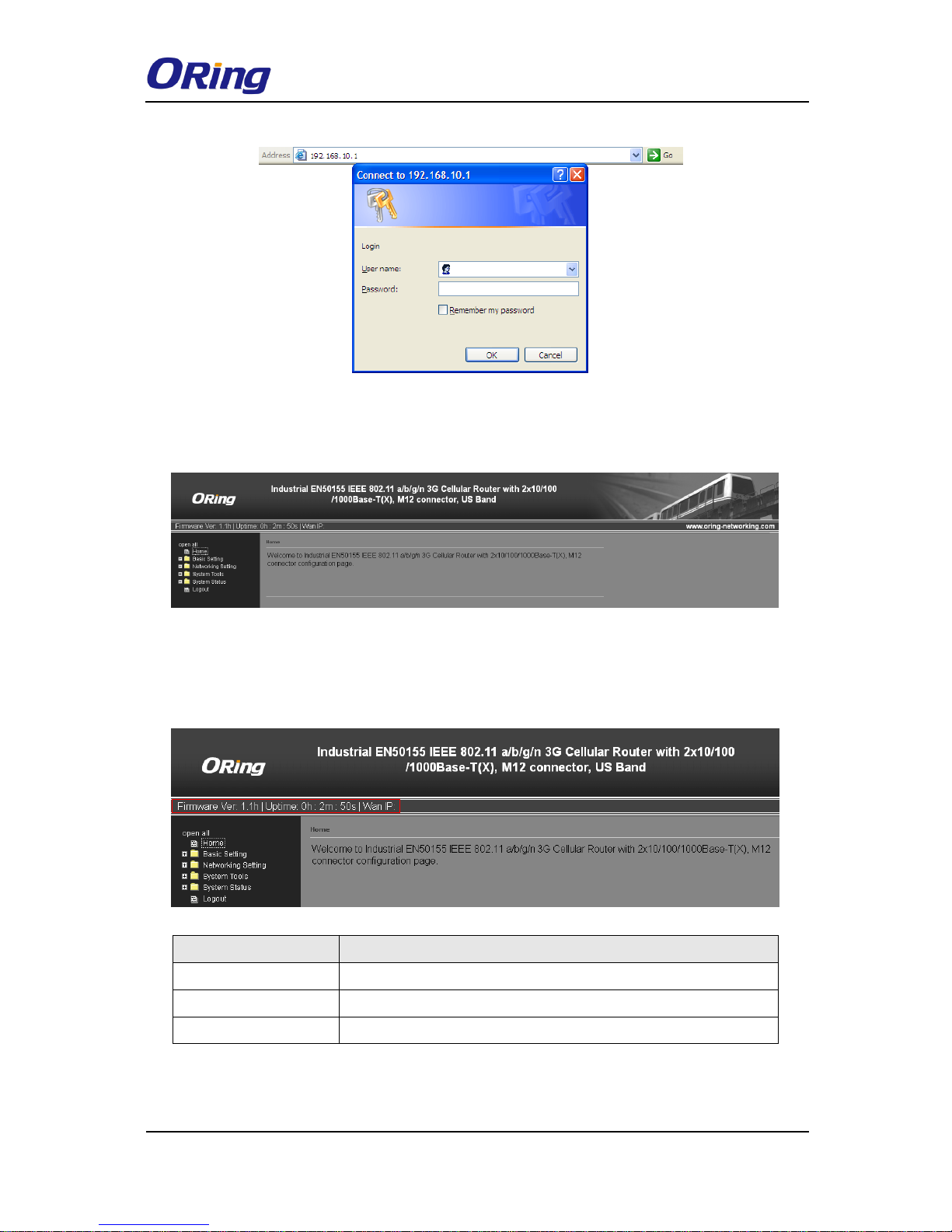
Step 3: Configure the router on a web-based management utility. Open a web browser on
your computer and type http://192.168.10.1 (default gateway IP of the router) in the address
box to access the webpage. A login window will pop up where you can enter the default login
name admin and password admin. For security reasons, we strongly recommend you to
change the password. Click on System Tools > Login Setting after logging in to change the
password.
TGAR-1062/2062/1662 Series User Manual
ORing Industrial Networking Corp. 17
After you log in successfully, a Web interface will appear, as shown below. On the left hand
side of the interface is a list of functions where you can configure the settings. The details of
the configurations will be shown on the right screen.
5.2 Configuration
On top of the Home screen shows information about the firmware version, uptime, and WAN
IP address.
Label
Description
Firmware
Shows the current firmware version
Uptime
Shows the elapsed time since the AP router is started
Wan IP
Shows WAN IP address
5.2.1 Basic Setting
This section will guide you through the general settings for the router.
 Loading...