

ORiNG TGAP-W6610+-M12, TGAP-W610+-M12 Quick Installation Manual
Quick InstallationGuide
Version 1.0
Quick Installation Guide
Introduction
PRINTED ON RECYCLED PAPER
The are reliable outdoor WLAN access points
with one or dual 802.11 a/b/g/n wireless
modules alongside one Gigabit LANport in M12connector. With EN50155
compliance and M12 connectors to ensure tight and robust connections,
the devices guarantee reliable operation against vibration and shock, and
are ideal for rolling stock applications. The devices havean IP-67
waterproof housingto protect themfrom damage inharsh weather when
installed outdoors.Featuring two orfour N-Type connectorsthat can house
any N-Type antennasfor extended communicationsdistances, the devices
are idealfor the toughestindustrial environments. Inaddition, the LANport of
the devicesis PoE-enabled, allowingthe device tobe powered overthe
existing network cable.The APscan be configuredto operate in
AP/Client/Bridge/AP-Client modesand support MACfilters for security
control. Configurationsand management canbe done viaa Window utilityor
Web interfaceon LAN orWLAN networks.
TGAP-W610+-/W6610+-M12
(TGAP-W610+) (TGAP-W6610+)
Package Contents
Wall-mount
Follow thesteps below toinstall the device to the wall.
Attach the mounting plate to the back of the device using four screws. The plate can
be attached vertically or horizontally to the device depending onthe space available.
Step 1:
The are shipped with the following items.If any
of these items is missing or damaged,please contact your customer service
representative for assistance.
TGAP-W610+/6610+-M12
For pinassignments of power,console andrelay output ports,please refer tothe following tables.
Contents
CD
TGAP-W6610+-M12
TGAP-W610+-M12
Pictures Number
1
1
1
2.4GHz/5GHz
Antenna
2 (TGAP-W610+-M12)or
4 (TGAP-W6610+-M12)
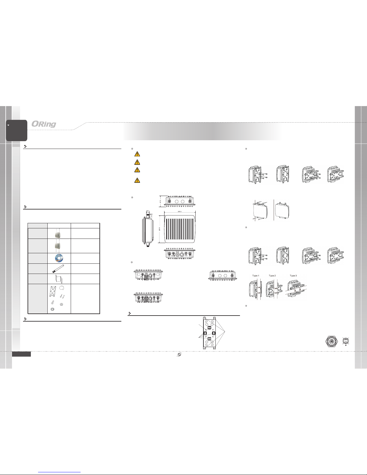
Dimension
Wireless
EN50155
ACCESS POINT
EN50155 Industrial IP-67 PoE
Outdoor Access Point
Wiring
Grounding
Grounding andwire routing helplimit the effectsof noise dueto electromagnetic interference
(EMI). Runthe ground connectionfrom the groundingpin on thepower connector tothe grounding
surface priorto connecting devices.
POWER PORTPINOUTS
The devicesupports two setsof power suppliesand uses theM12 5-pin
female connector on the front panel for the dual power inputs.
Insert a power cableto the powerconnector on thedevice.
Rotate theouter ring ofthe cable connectoruntil a snug fit is
achieved. Make sure the connection is tight.
Step 1:
Step 2:
QIG
1907-2-29-TGAPW-1.0
TGAP-W610+/6610+-M12 Series
TGAP-W610+/6610+-M12 Series
1
Preparation
Before youbegin installing thedevice, make sureyou have allof the package
contents availableand a PCwith Microsoft InternetExplorer 6.0 orlater, for
using web-basedsystem management tools.
When installedoutdoors, make surethe connectors onthe panel arefacing
down toprevent water intrusion.
Do not remove the water-proof casing, and do not touch or move the
device when the antennasare transmitting orreceiving signals.
When installingthe device, makesure to keepthe radiating ata minimum
distance of20 cm (7.9inches) from allpersons to minimizethe potential for
human contactduring normal operation.
Do notoperate the device near unshielded blasting caps or in an otherwise
explosive environment unless thedevice has beenmodified for suchuse by
qualified personnel.
Safety & Warnings
IP-67
PoE
Panel Layouts
Bottom Panel
1
TGAP-W6610+-M12
1. Powerconnector
2. LEDfor PWR1 status
3. LEDfor PWR2 status
4. LEDfor PoE status
5. LEDfor WLAN2 connection
6. LEDfor WLAN1 connection
7. LEDfor LAN portconnection
8. Resetbutton
9. LANport
10. Connectorfor WiFi2 antenna
342675
8 9 1010
1
TGAP-W610+-M12
342675
8 9
TopPanel
1 1
1. Antennaconnector
forWiFi(WiFi1)
Installation
The devicecan be fixedto a poleor the wall
using the supplied mounting plate. Make
sure theconnectors on thebottom panel are
facing downwhen installing toprevent water
intrusion.
Wallmount x1
Stainlesstie
backstraps x2
WoodScrew x4
Wood/Gyprock Plug x4
M6x12Screw x4
Washerx4
SpringWasher x4
QIG
Mounting
Installation
Package
1
Wall-mount
screw holes
Strap slotsfor
pole mounting
Screw holesfor
attaching the
plate tothe
unit
Vertical Horizontal
Step 2:
Step 3:
Hold the device upright against the wall.
Insert four screws through the holes at thetop and bottomof the plateand fasten the
screws to the wall.
Pole-mount
Youcan mount thedevice to apole using theadjustable steel bandstraps included inthe kit. Follow
the steps below:
Attach the mounting plate to the back of the device using four screws.The plate canbe
attached verticallyor horizontally tothe device basedon the spaceavailable.
Step 1:
Vertical Horizontal
Step 2: Thread the two supplied metal mounting straps through the large slots on the
mounting plateand then putthe straps aroundthe pole.
V1+
V1-
V2+
V2-
V1+
V1-
V2+
V2-
V1+
V1-
V2+
V2-
QIG
Quick InstallationGuide
Quick Installation Guide
ORing IndustrialNetworking Corp.
Copyright© 2014 ORing
All rightsreserved.
TEL: +886-2-2218-1066
FAX:+886-2-2218-1014
Website:www.oring-networking.com
E-mail: support@oring-networking.com
Version 1.0
QIG
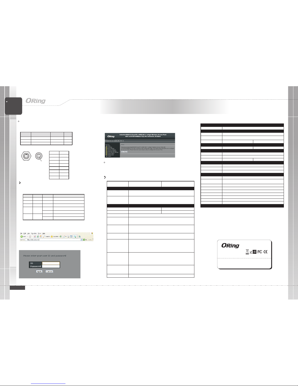
Configurations
After installingthe router and connecting cables, start the evice by
turning onpower. Thegreen power LEDshould turn on. Please refer to
the following tablet for LED indication.
d
1. Launchthe Internet Explorerand type inIP address ofthe device.The default static
IP addressis 192.168.10.2
Specifications
Follow thesteps below tolog in andaccess the system:
2. Login with defaultuser name andpassword (both are ).admin
3.After logging in,you should seethe following screen.For more informationon configurations, please
refer tothe user manual.For information onoperating the deviceusing ORing’s Open-Visionmanagement
utility,please go toORing website.
Resetting
Torestore the device configurations back to the factory defaults, press the button for a few
seconds. Once the power indicator starts to flash, release the button. The device will then reboot
and return to factory defaults.
Reset
Regulatory Approvals
FCCPart 15, CISPR(EN55022) class A,EN50155 (EN50121-3-2, EN55011,EN50121-4)
EMI
EN61000-4-2(ESD), EN61000-4-3 (RS),EN61000-4-4 (EFT), EN61000-4-5 (Surge),
EN61000-4-6(CS), EN61000-4-8, EN61000-4-11
EMS
IEC60068-2-27,EN61373
Shock
IEC60068-2-32
IEC60068-2-6,En61373
Vibration
Free Fall
Warranty
5years
Frequency Band
TransmissionRate
Encryption Security
WEP: (64-bit,128-bit keysupported)
WPA/WPA2:(WEP and AESencryption)
WPA-PSK(256-bit key pre-sharedkey supported)
802.1X Authenticationsupported
TKIP encryption
802.11i
Wireless Security
SSIDbroadcast disable
TransmitPower
ReceiverSenstivity
Protocol Support
Protocol
ARP,BOOTP,DHCP,DNS,HTTPs,IP,ICMP,SNTP,TCP,UDP,RADIUS,SNMP,STP,RSTP
LED Indicators
PowerIndicator
10/100/1000Base-T(X)port
Indicator
3x LEDs, PW1/PW2/ PoE GreenOn : Poweris on andbooting up PW1/PW2/ PoE
1x LED, Greenfor port Link/Act
WLAN LED
EN60950-1
Safety
ORing WLANAccess
Point Model
10/100/1000Base-T(X)Ports in
M12 AutoMDI/MDIX
(8-pin A-coding)
1
Physical Ports
Technology
Modulation
WLAN Interface
OperatingMode
Antenna andConnector
2 xExternal N typeantenna connector
RadioFrequency Type DSSS,OFDM
TGAP-W6610+-M12
IEEE802.11b:CCK, DQPSK, DBPSK
IEEE802.11g:OFDM with BPSK,QPSK, 16QAM, 64QAM
IEEE802.11a:OFDM with BPSK,QPSK, 16QAM, 64QAM
IEEE802.11n:OFDM with BPSK,QPSK, 16QAM, 64QAM
America /FCC : 2.412~2.462 GHz (11channels)
5.180~5.240 GHz& 5.745~5.825 GHz(9channels)
EuropeCE/ETSI:2.412~2.472Ghz(13channels)
5.180~5.240 Ghz(4 channels)
802.11a: -68dBm±2.0dB@ 54 Mbps
802.11b: -82dBm dB@ 11Mbps
802.11g: -68dBm dB@ 54Mbps
802.11gn HT20:-64dBm
±2.0
±2.0
±2.0dB @150Mbps
802.11gn HT40:-60dBm±2.0dB @300Mbps
802.11an HT20:-64dBm±2.0dB @150Mbps
802.11an HT40:-60dBm±2.0dB @300Mbps
2x LEDs, Greenfor WLAN Link/Ack
IEEE801.11b: 1/2/ 5.5/ 11Mbps
IEEE801.11a/g: 6/9/ 12/ 18/24/ 36/ 48/54 Mbps
IEEE802.11n: upto 300Mbps
802.11a: 12dBm dBm
802.11b: 18dBm dBm
802.11g: 15dBm dBm
802.11gn HT20:13dBm m@150Mbps
802.11gn HT40:12dBm m@300Mbps
802.11an HT20:12dBm m@150Mbps
802.11an HT40:12dBm dBm@300Mbps
±1.5
±1.5
±1.5
±1.5 dB
±1.5 dB
±1.5 dB
±1.5
TGAP-W610+-M12
PoEP.D.port
Present atETH
Fully compliantwith IEEE 802.3afPower Devicespecification
Overload & shortcircuit protection
IsolationVoltage:1000VDCmin.
Isolation Resistance: 10 ohms min
8
Dual AP/DualClient /Bridge /AP-ClientMode
4 xExternal N typeantenna connector
1x LED, Greenfor WLAN Link/Ack
Network Connection
TheAP has one10/100/1000 Base-T(X) Ethernetports. According tothe link type,the APuses
CAT3, 4, 5,5e, UTP cables to connect to any other network device (PCs,servers,
evicees, routers, or hubs). Please refer to the following table for cable specifications.d
Cable Type Max. Length Connector
10Base-T Ca t. 3, 4, 5 100-ohm UTP 100 m (328 f t) M12
100Base-T Cat. 5 100-ohm UTP UTP100 m (328 f t) M12
1000Base-T Cat. 5/Cat. 5e 100- ohm UTP UT P 100 m (328 f t) M12
M12/8P PinDefinition
4
5
6
7
8
21
3
PIN Definition
1BI_DC+
2BI_DD+
3BI_DD-
4BI_DA-
5BI_DB+
6BI_DA+
7BI_DC-
8BI_DB-
LED Color Status Descr iption
PWR1 Green On DC power 1 ac tivated
PWR2 Green On DC power 2 ac tivated
PoE Green On Power is suppl ied over E thernet cabl e
On Port is linked
ETH Green
Blinking Transmitting Data
On WLAN activatedWLAN
(1/2)
Green
Blinking Transm itting WLAN data
Power
PowerConsumption(Typ.)
11Watts
Physical Characteristic
Enclosure
IP-67
Dimension(WxDxH)
310(W)x 310(D) x87(H) mm (12.2x 12.2 x3.4 inch.)
Weight (g)
Environmental
-40to85C(-40to185F)
oo
StorageTemperature
5%to 95% Non-condensing
OperatingHumidity
-25to70C(-13to158F)
oo
OperatingTemperature
3980g
9Watts
3900g
EN50155
RailTraffic
EN60068-2-1
EN60068-2-2
Dry Heat
Cooling
Wireless
EN50155
ACCESS POINT
EN50155 Industrial IP-67 PoE
Outdoor Access Point
TGAP-W610+/6610+-M12 Series
IP-67
PoE
AP/Client /Bridge/AP-Client Mode
TGAP-W610+/6610+-M12 Series
 Loading...