

ORiNG TGAP-620-M12, TGAP-6620-M12 User Manual

TTGGAAPP--662200--//66662200--MM1122 SSeerriieess
IIEEEEEE 880022..1111 aa//bb//gg//nn AAcccceessss PPooiinntt wwiitthh
SSiinnggllee//DDuuaall RRFF
UUsseerr M
Maannuuaall
VVeerrssiioonn 11..00
JJaannuuaarryy,, 22001144
wwwwww..oorriinngg--nneettwwoorrkkiinngg..ccoomm

TGAP-620-/6620-M12 Series User Manual
ORing Industrial Networking Corp
1
COPYRIGHT NOTICE
Copyright © 2014 ORing Industrial Networking Corp.
All rights reserved.
No part of this publication may be reproduced in any form without the prior written consent of
ORing Industrial Networking Corp.
TRADEMARKS
is a registered trademark of ORing Industrial Networking Corp.
All other trademarks belong to their respective owners.
REGULATORY COMPLIANCE STATEMENT
Product(s) associated with this publication complies/comply with all applicable regulations.
Please refer to the Technical Specifications section for more details.
WARRANTY
ORing warrants that all ORing products are free from defects in material and workmanship
for a specified warranty period from the invoice date (5 years for most products). ORing will
repair or replace products found by ORing to be defective within this warranty period, with
shipment expenses apportioned by ORing and the distributor. This warranty does not cover
product modifications or repairs done by persons other than ORing-approved personnel, and
this warranty does not apply to ORing products that are misused, abused, improperly
installed, or damaged by accidents.
Please refer to the Technical Specifications section for the actual warranty period(s) of the
product(s) associated with this publication.
DISCLAIMER
Information in this publication is intended to be accurate. ORing shall not be responsible for
its use or infringements on third-parties as a result of its use. There may occasionally be
unintentional errors on this publication. ORing reserves the right to revise the contents of this
publication without notice.
CONTACT INFORMATION
ORing Industrial Networking Corp.
3F., No.542-2, Zhongzheng Rd., Xindian Dist., New Taipei City 23148, Taiwan (R.O.C.)
Tel: +886-2-2218-1066 // Fax: +886-2-2218-1014
Website: www.oring-networking.com
Technical Support
E-mail: support@oring-networking.com
Sales Contact
E-mail: sales@oring-networking.com (Headquarters)
sales@oring-networking.com.cn (China)

TGAP-620-/6620-M12 Series User Manual
ORing Industrial Networking Corp
2
Table of Content
Getting Started .............................................................................................. 4
1.1 About TGAP-620-/6620-M12................................................................................. 4
1.2 Software Features ................................................................ ................................ 4
1.3 Hardware Features ............................................................................................... 4
Hardware Overview ....................................................................................... 5
2.1 Front Panel ........................................................................................................... 5
2.1.1 Ports and Connectors ............................................................................................... 5
2.1.2 Front Panel LEDs ...................................................................................................... 7
2.2 Side Panel ............................................................................................................ 7
Hardware Installation .................................................................................... 8
3.1 Wall Mounting Installation ................................ ..................................................... 8
3.2 Wiring ................................................................................................................... 9
3.2.1 Grounding .................................................................................................................. 9
3.2.2 Power Port Pinouts ................................................................................................... 9
3.2.3 Relay Output Port Pinouts ...................................................................................... 10
Cables and Antenna ..................................................................................... 11
4.1 Ethernet Pin Definition ........................................................................................ 11
4.2 Console Port Pin Definition ................................................................................. 11
4.3 DI/DO ................................................................................................................. 12
4.4 Wireless Antenna ................................................................................................ 12
Management ................................................................................................ 13
5.1 Network Connection ........................................................................................... 13
5.2 Open-Vision Configuration ..................................................................................... 13
5.3 UPnP Equipment ................................................................................................ 14
5.4 Web Browser Management ................................................................................. 15
5.5 Configurations .................................................................................................... 16
5.5.1 Overview ........................................................................................................ 16
5.5.2 Basic Setting ................................................................ ............................................ 17
5.5.3 Wireless Setting ...................................................................................................... 21
5.5.4 Advanced Setting .................................................................................................... 32
5.5.5 Event Warning Settings .......................................................................................... 34
5.5.6 System status .......................................................................................................... 37

TGAP-620-/6620-M12 Series User Manual
ORing Industrial Networking Corp
3
5.5.7 Administrator ................................................................................................ .. 38
Technical Specifications ............................................................................ 41
Compliance .................................................................................................. 43
TGAP-620-/6620-M12 Series User Manual
ORing Industrial Networking Corp
4
Getting Started
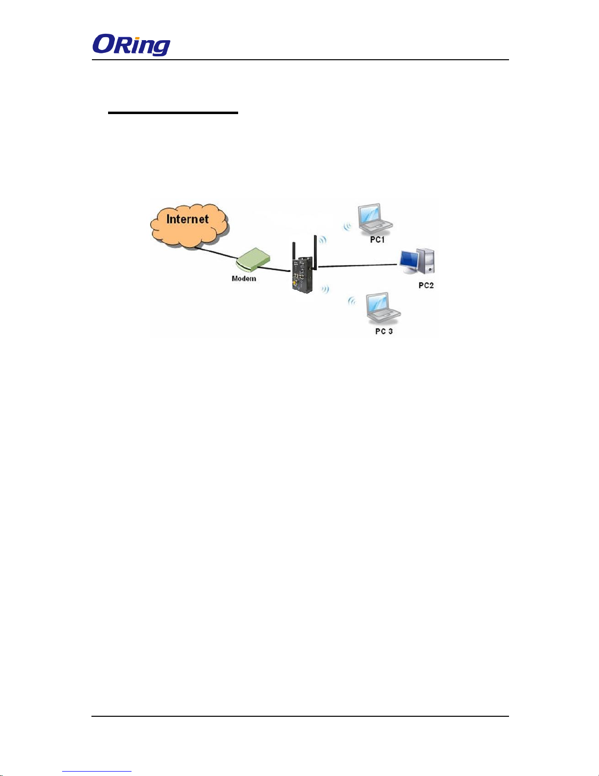
1.1 About TGAP-620-/6620-M12
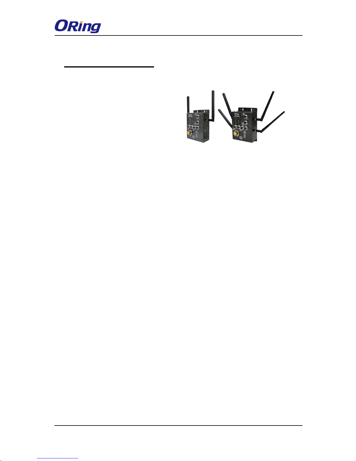
The TGAP-620-/6620-M12 are reliable
outdoor WLAN access points with one
(TGAP-620-M12) or dual (TGAP-6620-M12)
802.11 a/b/g/n wireless modules alongside
two Gigabit LAN ports in M12 connectors.
The two Ethernet ports allow you to form
Daisy Chain structure to reduce the use of
the ports. With EN50155 compliance and M12 connectors to ensure tight and robust
connections, the devices guarantee reliable operation against environmental disturbances,
such as vibration and shock, and are ideal for rolling stock applications. The APs can be
configured to operate in AP/Client/Bridge/AP-Client modes and support MAC filters for
security control. The devices can be configured and managed via a Window utility or Web
interface on LAN or WLAN networks.
1.2 Software Features
High speed air connectivity with support up to 300Mbps
Highly secure transmission with WEP/WPA/WPA2/Radius/TKIP supported
Supports AP/Client/Bridge/AP-Client modes
Supports Daisy Chain to reduce use of AP ports
Secure management with HTTPS
Event warning via Syslog, e-mail, SNMP traps, and relay
1.3 Hardware Features
2 x 10/100/1000 Base-T(X) Ethernet ports
Operating temperature: -25 to 70°C
Storage temperature: -40 to 85°C
Operating humidity: 5% to 95%, non-condensing
Dimensions(W x D x H): 125.6(W) x 65(D) x 196.1(H) mm
TGAP-620-/6620-M12 Series User Manual
ORing Industrial Networking Corp
5
Hardware Overview
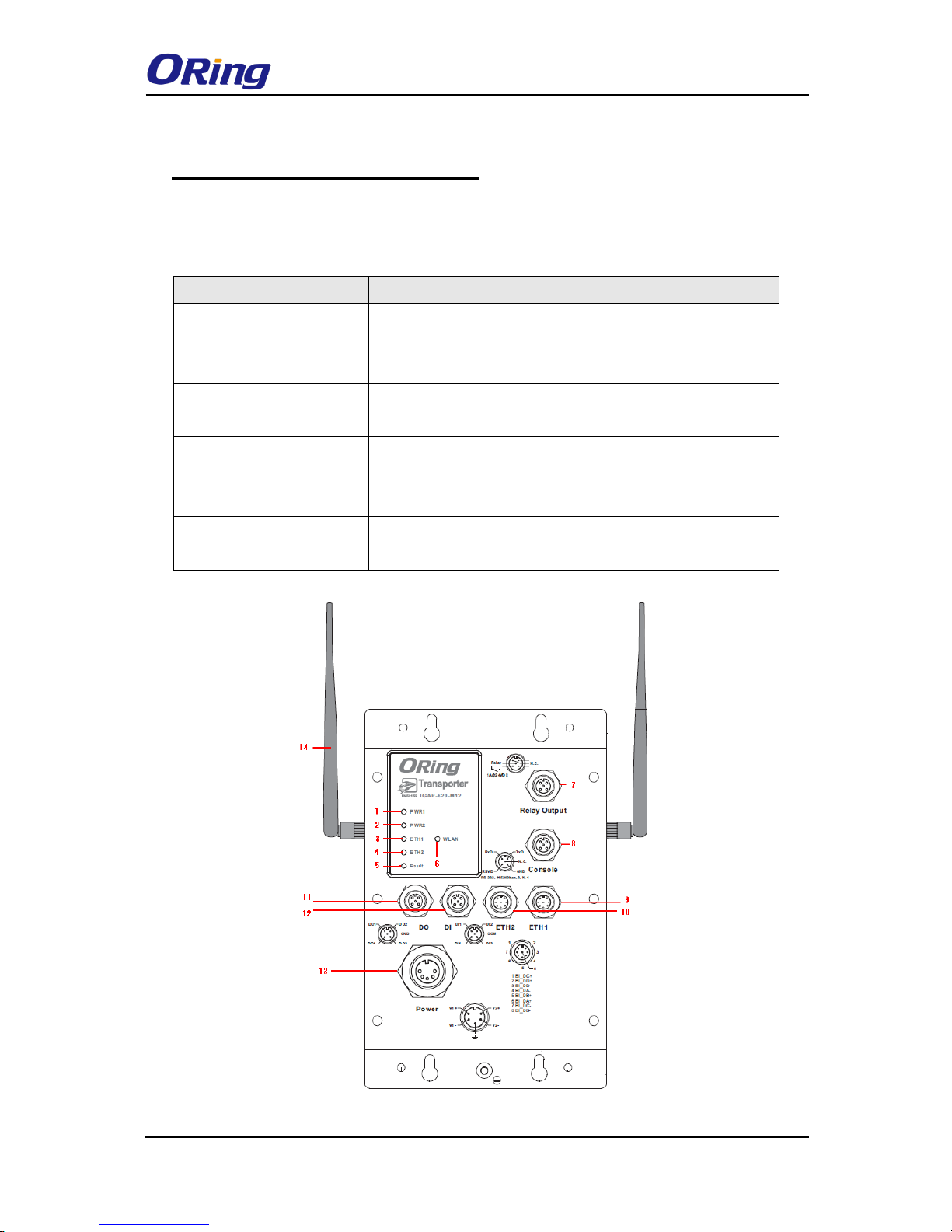
2.1 Front Panel
2.1.1 Ports and Connectors
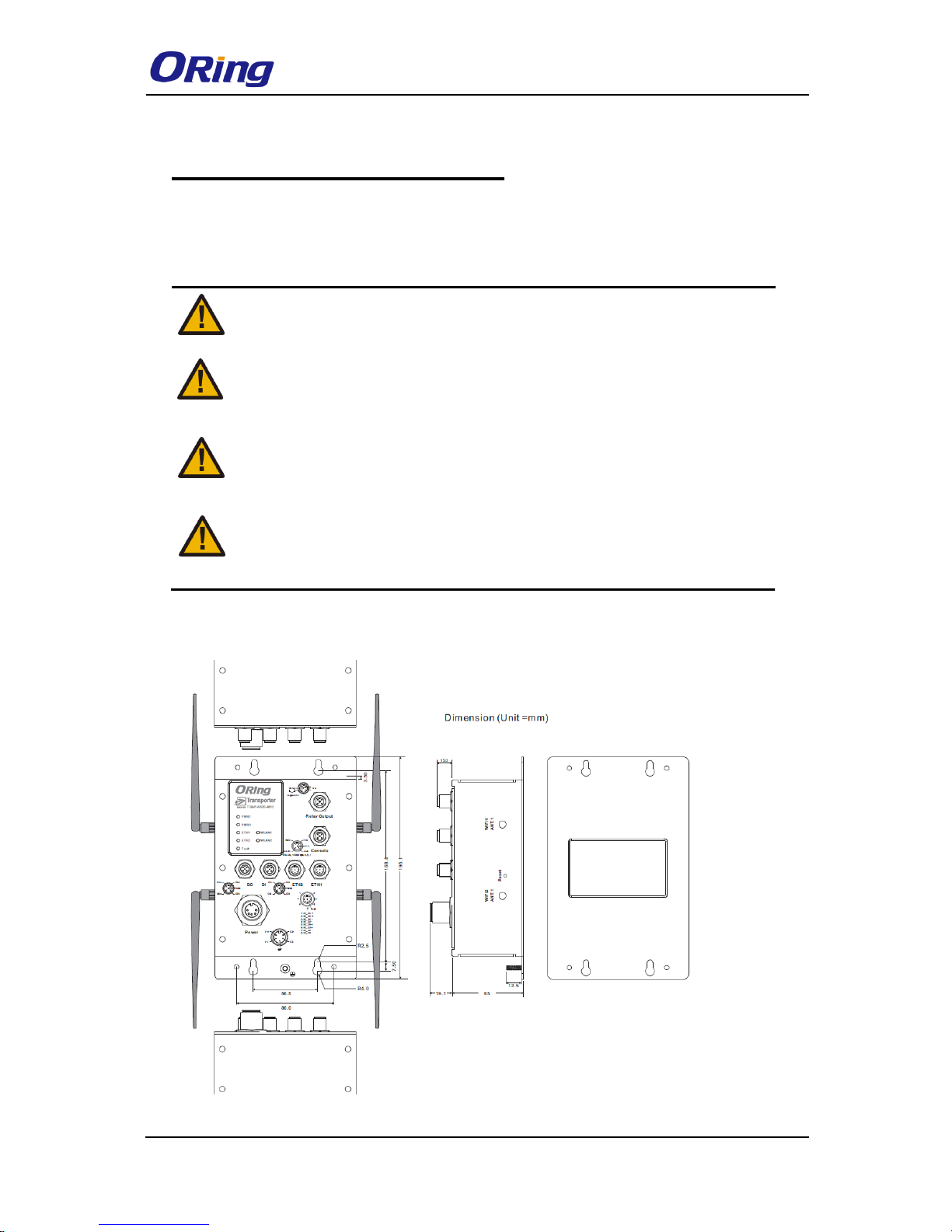
The devices are equipped with the following ports and features on the front panel.
Port
Description
10/100/1000 Base-T(X)
Ethernet ports with M12
connectors (D-coding)
2 x 10/100/1000 Base-T(X) ports supporting
auto-negotiation.
Relay output with M12
(A-coding) connector
1 x relay output to carry capacity of 3A at 24VDC
M23 power connector
with redundant power
inputs
Dual power inputs for 12~48 VDC
DIDO with M12 connector
(D-coding)
4 x digital input / 4 x digital output
TGAP-620-M12
TGAP-620-/6620-M12 Series User Manual
ORing Industrial Networking Corp
6
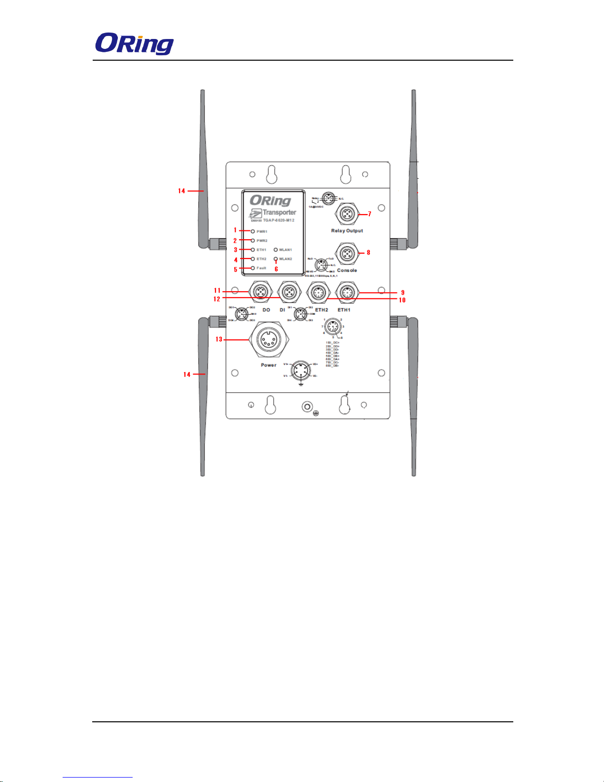
TGAP-6620
1. LED for PWR1 status
2. LED for PWR2 status
3. LED for Ethernet port 1 status
4. LED for Ethernet port 2 status
5. LED for fault relay
6. LED for WLAN connection
7. Fault relay connector
8. Console & Backup unit port
9. Ethernet port 1
10. Ethernet port 2
11. Digital output
12. Digital input
13. Power connector
14. 2.4/5GHz antenna
TGAP-620-/6620-M12 Series User Manual
ORing Industrial Networking Corp
7
2.1.2 Front Panel LEDs
LED
Color
Status
Description
PWR1
Green
Green On
DC power 1 activated
PWR2
Green
Green On
DC power 2 activated
ETH1
Green
On
Port is linked link
Blinking
Transmitting data
ETH2
Green
On
Port is linked link
Blinking
Transmitting data
WLAN (1/2)
Green
On
WLAN activated
Blinking
Transmitting WLAN data
Fault
Red
On
Fault relay. Power failure or Port
down/fail.
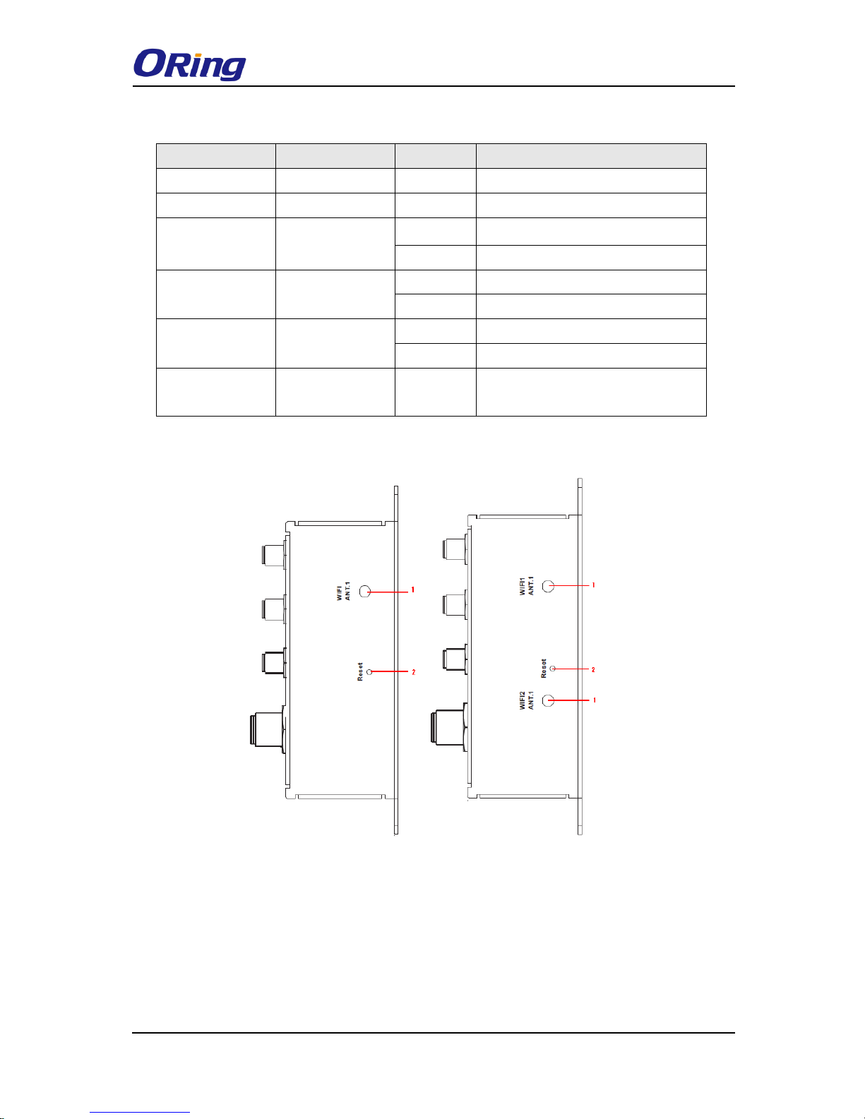
2.2 Side Panel
TGAP-620-M12 TGAP-6620-M12
Note: to restore the device configurations back to the factory defaults, press the Reset button
for a few seconds. Once the power indicator starts to flash, release the button. The device
will then reboot and return to factory defaults.
1. Antenna connector
2. Reset button
TGAP-620-/6620-M12 Series User Manual
ORing Industrial Networking Corp
8
Hardware Installation
Before installing the devices, make sure you have all of the package contents available and a
PC with Microsoft Internet Explorer 6.0 or later, for using web-based system management
tools.
When installed outdoors, make sure the connectors on the panel are facing down
to prevent water intrusion.
Do not remove the water-proof casing, and do not touch or move the device when
the antennas are transmitting or receiving signals.
When installing the device, make sure to keep the radiating at a minimum
distance of 20 cm (7.9 inches) from all persons to minimize the potential for
human contact during normal operation.
Do not operate the device near unshielded blasting caps or in an otherwise
explosive environment unless the device has been modified for such use by
qualified personnel.
3.1 Wall Mounting Installation
Wall-mount Measurements

TGAP-620-/6620-M12 Series User Manual
ORing Industrial Networking Corp
9
The device can be fixed to the wall. Follow the steps below to install the device on the wall.
Step 1: Hold the AP upright against the wall
Step 2: Insert four screws through the large opening of the keyhole-shaped apertures at the
top and bottom of the unit and fasten the screw to the wall with a screwdriver.
Step 3: Slide the AP downwards and tighten the four screws for added stability.
Instead of screwing the screws in all the way, it is advised to leave a space of
about 2mm to allow room for sliding the AP between the wall and the screws.
3.2 Wiring
For pin assignments of power, console and relay output ports, please refer to the following
tables.
3.2.1 Grounding
Grounding and wire routing help limit the effects of noise due to electromagnetic interference
(EMI). Run the ground connection from the grounding pin on the power connector to the
grounding surface prior to connecting devices.
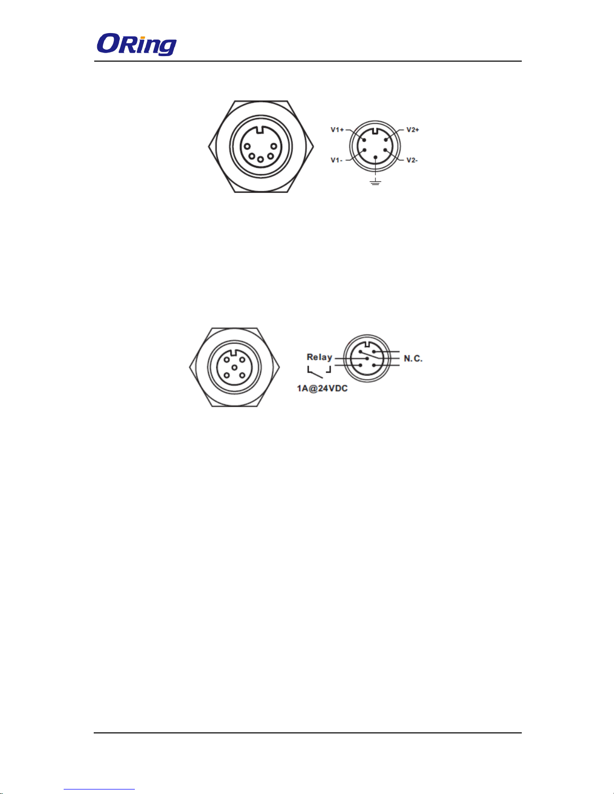
3.2.2 Power Port Pinouts
The device supports two sets of power supplies and uses the M23 5-pin female connector on
the front panel for the dual power inputs.
Step 1: Insert a power cable to the power connector on the device.
Step 2: Rotate the outer ring of the cable connector until a snug fit is achieved. Make sure
the connection is tight.
TGAP-620-/6620-M12 Series User Manual
ORing Industrial Networking Corp
10
3.2.3 Relay Output Port Pinouts
The APs use the M12 A-coded 5-pin male connector on the front panel for relay output. Use
a power cord with an M12 A-coded 5-pin female connector to connect the relay. The relay
contacts will detect user-configured events and form an open circuit when an event is
triggered.
TGAP-620-/6620-M12 Series User Manual
ORing Industrial Networking Corp
11
Cables and Antenna
4.1 Ethernet Pin Definition
The AP has two 10/100/1000 Base-T(X) Ethernet ports. According to the link type, the AP
uses CAT 3, 4, 5, 5e, UTP cables to connect to any other network device (PCs, servers,
switches, routers, or hubs). Please refer to the following table for cable specifications.
Cable
Type
Max. Length
Connector
10Base-T
Cat. 3, 4, 5 100-ohm
UTP 100 m (328 ft)
M12
100Base-T(X)
Cat. 5 100-ohm UTP
UTP 100 m (328 ft)
M12
1000BASE-T
Cat. 5/Cat. 5e 100-ohm UTP
UTP 100 m (328ft)
M12
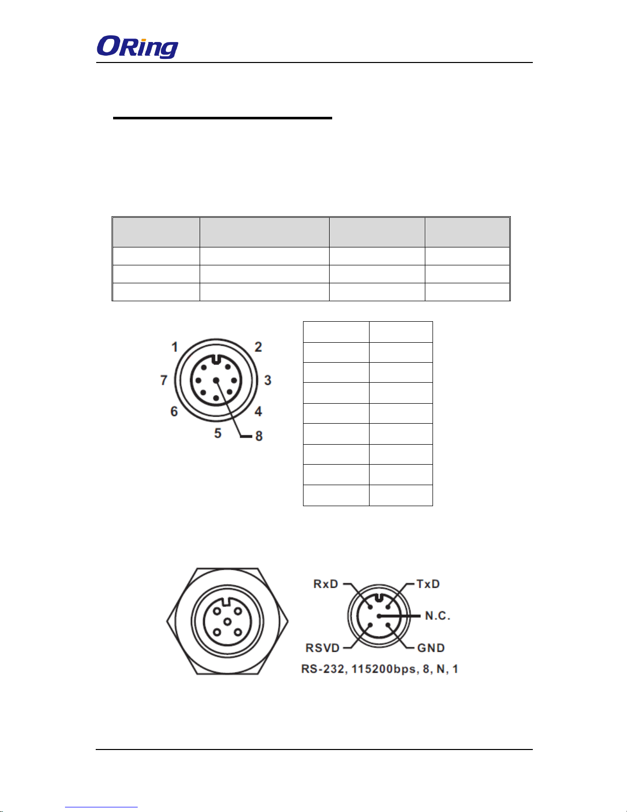
4.2 Console Port Pin Definition
PIN
Definition
1
BI_DC+
2
BI_DD+
3
BI_DD-
4
BI_DA-
5
BI_DB+
6
BI_DA+
7
BI_DC-
8
BI_DB-
TGAP-620-/6620-M12 Series User Manual
ORing Industrial Networking Corp
12
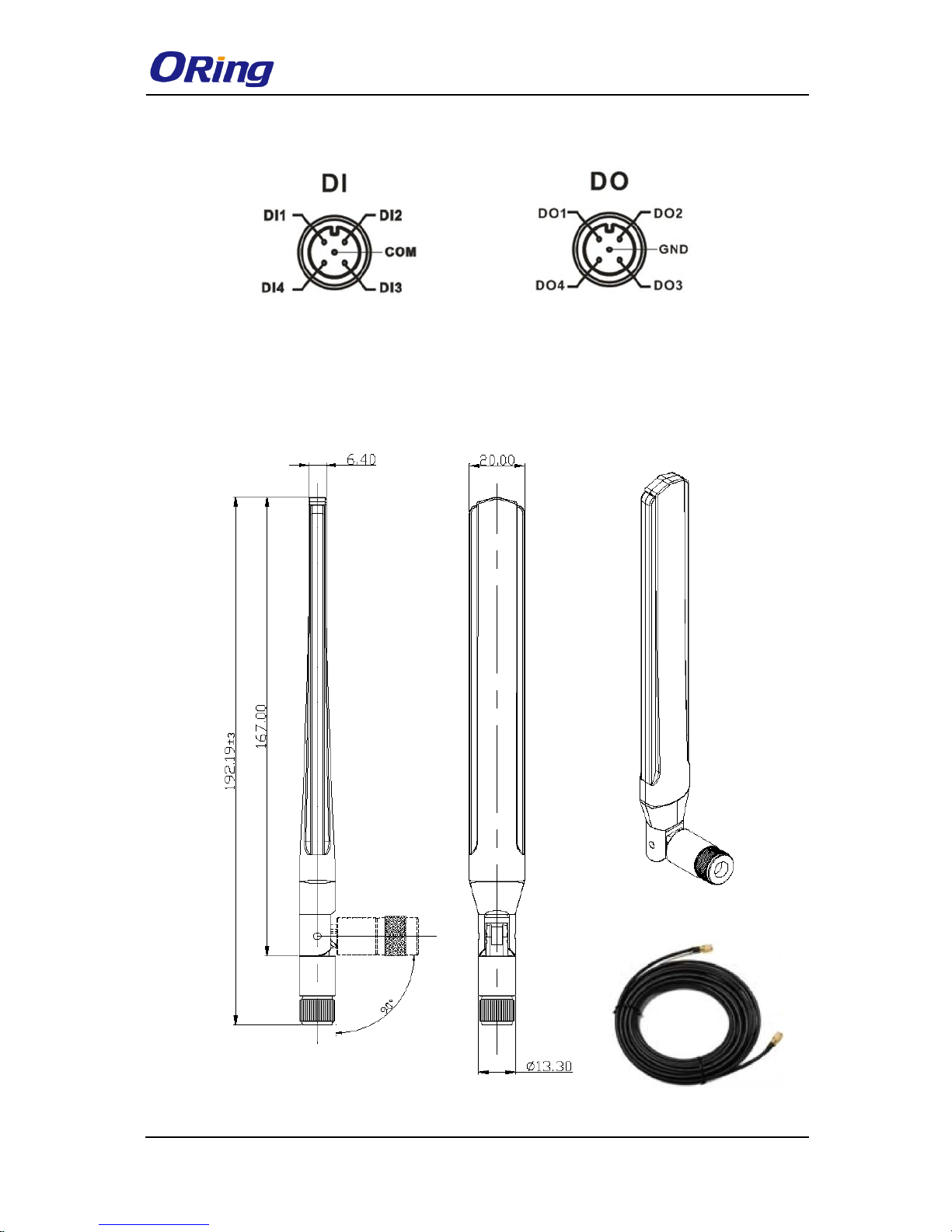
4.3 DI/DO
4.4 Wireless Antenna
The series uses 2.4GHz/5GHz antennas with reversed SMA connectors. You can also use
external RF cables and antennas with the connectors.
TGAP-620-/6620-M12 Series User Manual
ORing Industrial Networking Corp
13
Management
5.1 Network Connection
Before installing the device, you need to be able to access the device via a computer
equipped with an Ethernet card or wireless LAN interface. To simplify the connection, it is
recommended to use an Ethernet card to connect to a LAN.
Follow the steps below to install and connect the device to PCs:
Connect a computer to the device. Use either a straight-through Ethernet cable or cross-over
cable to connect the LAN port of the device to a computer. Once the LED of the LAN port
lights up, which indicates the connection is established, the computer will initiate a DHCP
request to retrieve an IP address from the AP.
5.2 Open-Vision Configuration
The device can be configured using ORing’s proprietary Windows utility Open-Vision. Follow
the steps below to set up the device in Open-Vision.
Step 1: Open the commander and click Discover, a list of AP devices will be shown.
Step 2: Choose your access point. The functions of the AP will be shown in a tree structure.
Step 3: Type in the username and password to log in to setup the AP.
 Loading...