

ORiNG TES-180-M12 Quick Installation Manual
Version 1.0
Cable Type Max.Length Connector
10BASE- T Cat. 3 , 4, 5 100-o hm UTP 100 m (32 8f t)
4-pin fem ale M12
D-coding connector
100BAS E-TX Cat. 5 100 -ohm UTP UTP 10 0m (328 ft)
4-pin fem ale M12
D-coding connector
Pin No. Descri ption
#1
RD+
#2
TD+
#3
RD-
#4
TD-
LED Color Status Descr iption
PWR Green On DC power modul e is activate d
10/100Base- T(X)
On Port i s Linked
LNK/ACT G reen
Blink ing Transmitti ng data
On Port i s in duplex m odeDupl ex /
Collision
Amber
Blinking Colli sion occurs
EN50155
Switch
INDUSTRIAL
Quick Installation Guide
Introduction
The unmanaged Ethernet switche is designed for industrial
TES-180-M12
applications, such as rolling stock, vehicle, and railway applications. The
switch boasts EN50155 compliance and M12 connectors to ensure tight
and robust connections, and guarantee reliable operation against
environmental disturbances, such as vibration and shock. With eight
10/100Base-T(X) ports, the switch provides a wide operating temperature
range from -40 C to 70 C.
Package Contents
The device is shipped with the following items. If any of these items is missing
or damaged, please contact your customer service representative for
assistance.
TES-180-M12
QIG
Preparation
Before you begin installing the device, make sure you have all of the package
contents available and a PC with Microsoft Internet Explorer 6.0 or later, for
using web-based system management tools.
Safety & Warnings
oo
Contents
Pictures Number
1
1
Elevated OperatingAmbient:
If installed in a closed environment, make sure
the operating ambient temperature is compatible with the maximum
ambient temperature (Tma) specified by the manufacturer.
Reduced Air Flow:
Make surethe amount of airflow required for safeoperation
of the equipment is not compromised during installation.
Mechanical Loading:
Make surethe mounting of theequipment is not in a
hazardous condition due to uneven mechanical loading.
Circuit Overloading:
Consideration shouldbe given to theconnection of the
equipment to the supply circuit andthe effect that overloading of the circuits
might have on overcurrent protection andsupply wiring. Appropriate
consideration ofequipment nameplate ratings shouldbe used when addressing
this concern.
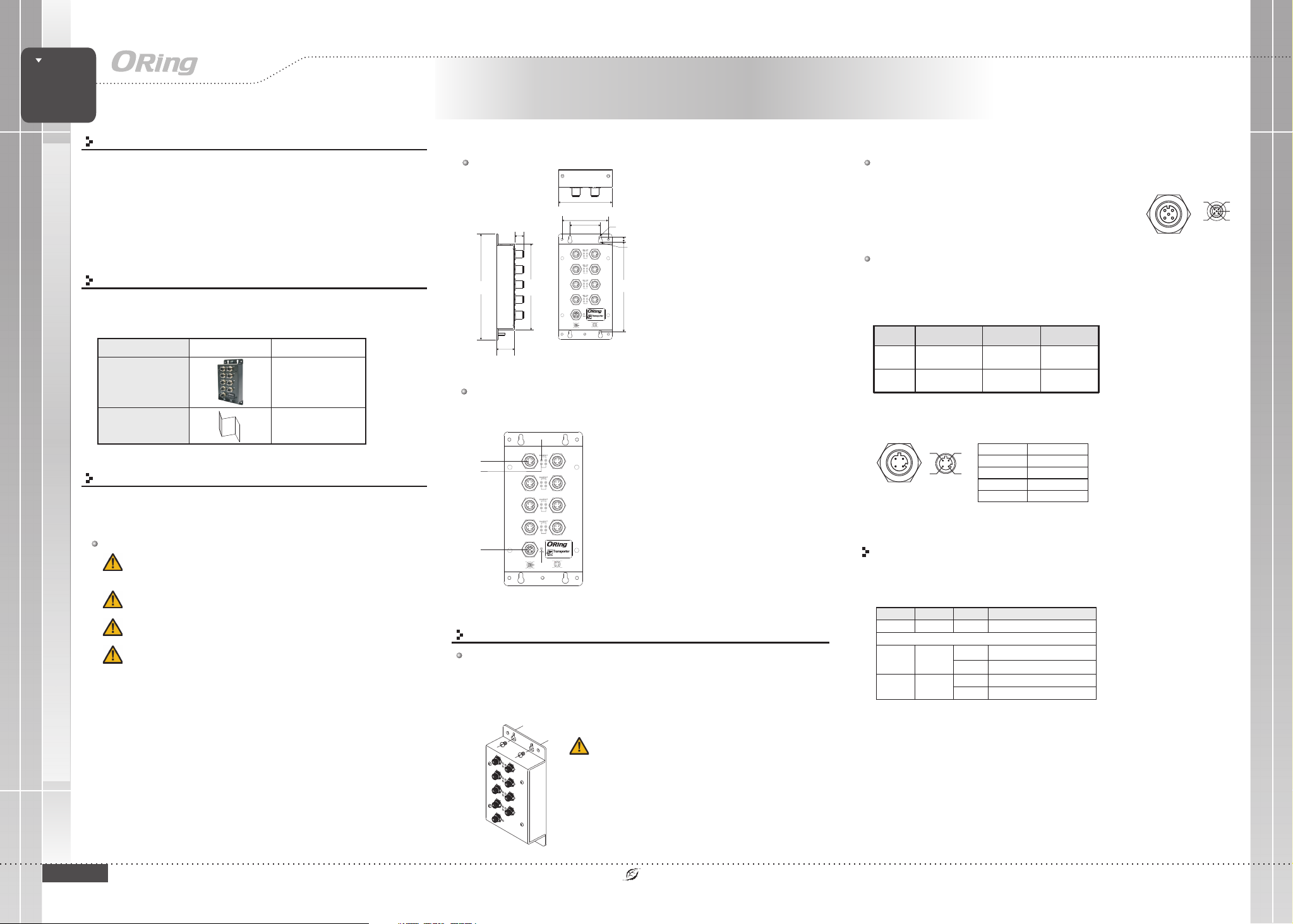
TES-180-M12
Dimension
88.9
73.9
44.4
15.0
P1 P2
P3 P4
P5 P6
178.2
138.0
P7 P8
PWR
12-48VDC
N.C.
V-
40.0
Panel Layouts
Front View
3
1
4
2
P1 P2
FDX
P3 P4
FDX
P5 P6
FDX
P7 P8
FDX
PWR
TES-180-M12
Tx+
12-48VDC
V+
N.C.
N.C.
5
V-
N.C.
Rx+
Tx-Rx-
Installation
Wall-mount
The devicecan be fixed tothe wall. Follow thesteps below to installthe device on thewall.
Step 1:
Step 2:
top and bottom of the unit and fasten the screw to the wall with a screwdriver.
Step 3:
d
Hold the evice upright against the wall
Insert four screws through the large opening of the keyhole-shaped apertures at the
Slide the evice downwards and tighten the four screws for added stability.
d
R2.5
7.50
FDX
FDX
FDX
FDX
V+
N.C.
N.C.
R4.00
150.0
TES-180-M12
Rx+
Tx+
Tx-Rx-
1. Ethernet port
2. Power port
3. LNK/ACT LED for LAN ports
4. Duplex/Collision LED for LAN ports
5. Power status LED
EN50155 8-port unmanaged
Ethernet switch
Wiring
Power portpinouts
The devicesupports power supply inM12 5-pin female connector on
the front panel for the dual power inputs.
Insert a power cable to the power connector on the device.
Step 1:
Rotate the outerring of the cableconnector until a snug fit is
Step 2:
achieved. Make sure the connection is tight.
Network Connection
The switch haseight 10/100Base-T(X) Ethernet portsin the form ofM12 connector. Depending on
the linktype, the switch uses CAT 3, 4,5, 5e UTP cables to connect to network devices (PCs,
servers, switches, routers, or hubs). Please refer to the followingtable for cable specifications.
M12/4P Pin Definition
For pin assignments of the LAN ports, please refer tothe following tables.
Rx+
Tx+
Rx-
Tx-
Configurations
After installing the switch and connecting cables, start the evice by turning on
power. The green power LED should turn on. Please refer to the following tablet
for LED indication.
d
N.C.
V-
V+
N.C.
N.C.
QIG
TES-180-M12
1907-2-29-TES180M12-1.0
Instead ofscrewing the screws inall the way, it is advisedto
leave a space of about 2mmto allow room forsliding the switch
between thewall and the screws.
PRINTED ON RECYCLED PAPER
Quick Installation Guide
Version 1.0
EN50155
Switch
INDUSTRIAL
Quick Installation Guide
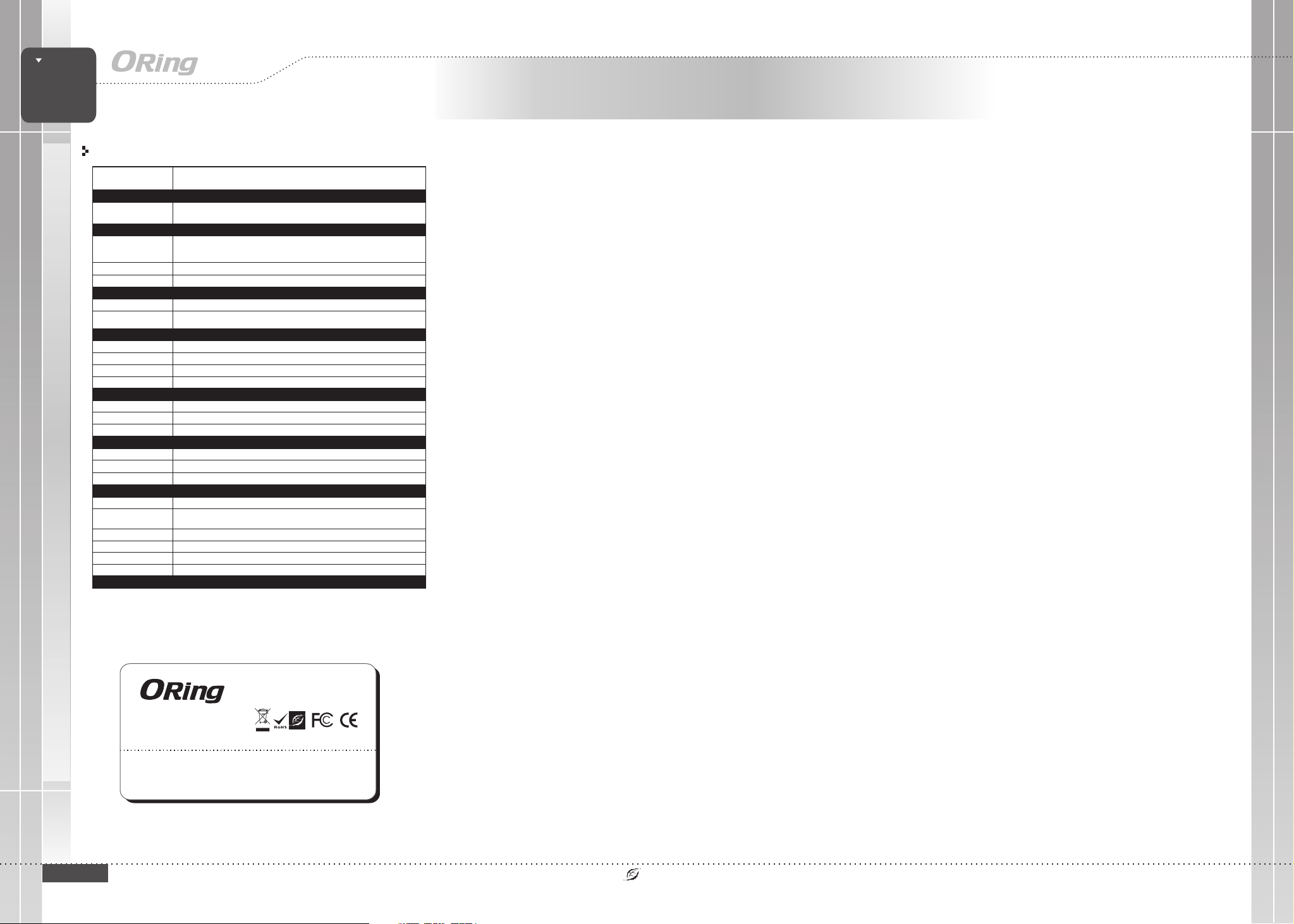
Specifications
ORing SwitchModel
Physical Ports
10/100Base-T(X) Ports
in M12
Technology
Ethernet Standards
MAC Table
Processing
LED Indicators
Power Indicator
10/100Base-T(X) M12 Port
Indicator
Power
Redundant InputPower
Power Consumption(Typ.)
Overload CurrentProtection
Reverse Polarity Protection
Physical Characteristic
Enclosure
Dimension(WxDxH)
Weigh t( g)
Environmental
Storage Temperature
Operating Temperature
Operating Humidity
Regulatory Approvals
EMI
EMS
Shock
Free Fall
Vibration
Safety
Warranty
IEEE 802.3for 10Base-T
IEEE 802.3ufor 100Base-TX
IEEE 802.3xfor Flow control
8192 MACaddresses
Store-and-Forward
Green: PowerLED x 1
Green forport Link/Act. Amber for Duplex/Collision
12~48VDC onM12 connector
4.32 Watts
Present
Present
IP-40
88.9 (w)x 40 (D)x178.2 (H) mm(3.5 x 1.57x 7.02 inch.)
510 g
oo
-40to85C(-40to185F)
oo
-40to70C(-40to158F)
5% to95% Non-condensing
FCC Part15, CISPR (EN55022)class A, EN50155(EN50121-3-2, EN55011, EN50121-4)
EN61000-4-2 (ESD),EN61000-4-3 (RS), EN61000-4-4(EFT), EN61000-4-5 (Surge),
EN61000-4-6 (CS),EN61000-4-8, EN61000-4-11
IEC60068-2-27
IEC60068-2-32
IEC60068-2-6
EN60950-1
5 years
TES-180-M12
8xM12connector(4pinD-coding)
EN50155 8-port unmanaged
TES-180-M12
Ethernet switch
QIG
QIG
Copyright© 2014 ORing
All rightsreserved.
ORing Industrial Networking Corp.
TEL: +886-2-2218-1066
FAX: +886-2-2218-1014
Website: www.oring-networking.com
E-mail: support@oring-networking.com
TES-180-M12
PRINTED ON RECYCLED PAPER
Quick Installation Guide
 Loading...