

ORiNG TAR-120-M12, TAR-3120-M12 User Manual
TTAARR--112200--MM1122 // TTAARR--33112200--MM1122
EENN5500115555 IIEEEEEE 880022..1111 CCeelllluullaarr VVPPNN RRoouutteerr
UUsseerr’’ss M
Maannuuaall
VVeerrssiioonn 11..00
JJuunnee,, 22001111
wwwwww..oorriinngg--nneettwwoorrkkiinngg..ccoomm

ORing Industrial Networking Corp.
COPYRIGHT NOTICE
Copyright © 2011 ORing Industrial Networking Corp.
All rights reserved.
No part of this publication may be reproduced in any form without the prior written consent of
ORing Industrial Networking Corp.
TRADEMARKS
is a registered trademark of ORing Industrial Networking Corp.
All other trademarks belong to their respective owners.
REGULATORY COMPLIANCE STATEMENT
Product(s) associated with this publication complies/comply with all applicable regulations.
Please refer to the Technical Specifications section for more details.
WARRANTY
ORing warrants that all ORing products are free from defects in material and workmanship for
a specified warranty period from the invoice date (5 years for most products). ORing will repair
or replace products found by ORing to be defective within this warranty period, with shipment
expenses apportioned by ORing and the distributor. This warranty does not cover product
modifications or repairs done by persons other than ORing-approved personnel, and this
warranty does not apply to ORing products that are misused, abused, improperly installed, or
damaged by accidents.
Please refer to the Technical Specifications section for the actual warranty period(s) of the
product(s) associated with this publication.
DISCLAIMER
Information in this publication is intended to be accurate. ORing shall not be responsible for its
use or infringements on third-parties as a result of its use. There may occasionally be
unintentional errors on this publication. ORing reserves the right to revise the contents of this
publication without notice.
CONTACT INFORMATION
ORing Industrial Networking Corp.
3F., No.542-2, Zhongzheng Rd., Xindian Dist., New Taipei City 23148, Taiwan
Tel: +886-2-2218-1066 // Fax: +886-2-2218-1014
Website: www.oring-networking.com
Technical Support
E-mail: support@oring-networking.com
Sales Contact
E-mail: sales@oring-networking.com
(Headquarters)
sales@oring-networking.com.cn
(China)

Table of Contents
Getting to Know your Wireless AP Router .................................................. 1
1.1 Overview .............................................................................................................................. 1
1.2 Software Features .............................................................................................................. 1
1.3 Hardware Features ............................................................................................................. 2
Hardware Installation .................................................................................... 3
2.1 Wall Mounting Installation .................................................................................................. 3
Hardware Overview ....................................................................................... 5
3.1 Front Panel .......................................................................................................................... 5
3.2 Front Panel LEDs ............................................................................................................... 7
Cables and Antenna ...................................................................................... 9
4.1 Ethernet Cables .................................................................................................................. 9
4.2 100BASE-TX/10BASE-T Pin Assignments ..................................................................... 9
4.3 Wireless Antenna .............................................................................................................. 10
Management Interface ................................................................................. 11
5.1 First-time Installation ........................................................................................................ 11
5.2 Configure the Wireless Router ........................................................................................ 14
5.3 Main Interface .................................................................................................................... 14
5.3.1 Basic Setting ................................................................................................................... 15
WAN......................................................................................................................................... 15
LAN ......................................................................................................................................... 20
DHCP ....................................................................................................................................... 21
Wireless .................................................................................................................................... 23
5.3.2 Advanced Setting ............................................................................................................ 28
Wireless .................................................................................................................................... 28
NAT Setting .............................................................................................................................. 30
Security Setting ........................................................................................................................ 34
VPN Setting ............................................................................................................................. 35
Routing Protocol (Routing Setting) .......................................................................................... 42
Notification .............................................................................................................................. 44
Miscellaneous (DDNS) ............................................................................................................ 47
5.3.3 System Tools ................................................................................................................... 48
Date & Time ............................................................................................................................. 48
Login Setting ............................................................................................................................ 49
Router Restart ........................................................................................................................... 50
Firmware Upgrade ................................................................................................................... 51

ORing Industrial Networking Corp.
Save/Restore Configurations .................................................................................................... 51
Miscellaneous (Ping) ................................................................................................................ 52
5.3.4 System Status .................................................................................................................. 53
System Info .............................................................................................................................. 53
System Log .............................................................................................................................. 53
Traffic Statistics........................................................................................................................ 54
Wired/Wireless Clients ............................................................................................................. 54
Technical Specifications .............................................................................55

TAR-120-M12 / TAR-3120-M12 User’s Manual
ORing Industrial Networking Corp. 1
Getting to Know your Wireless AP
Router
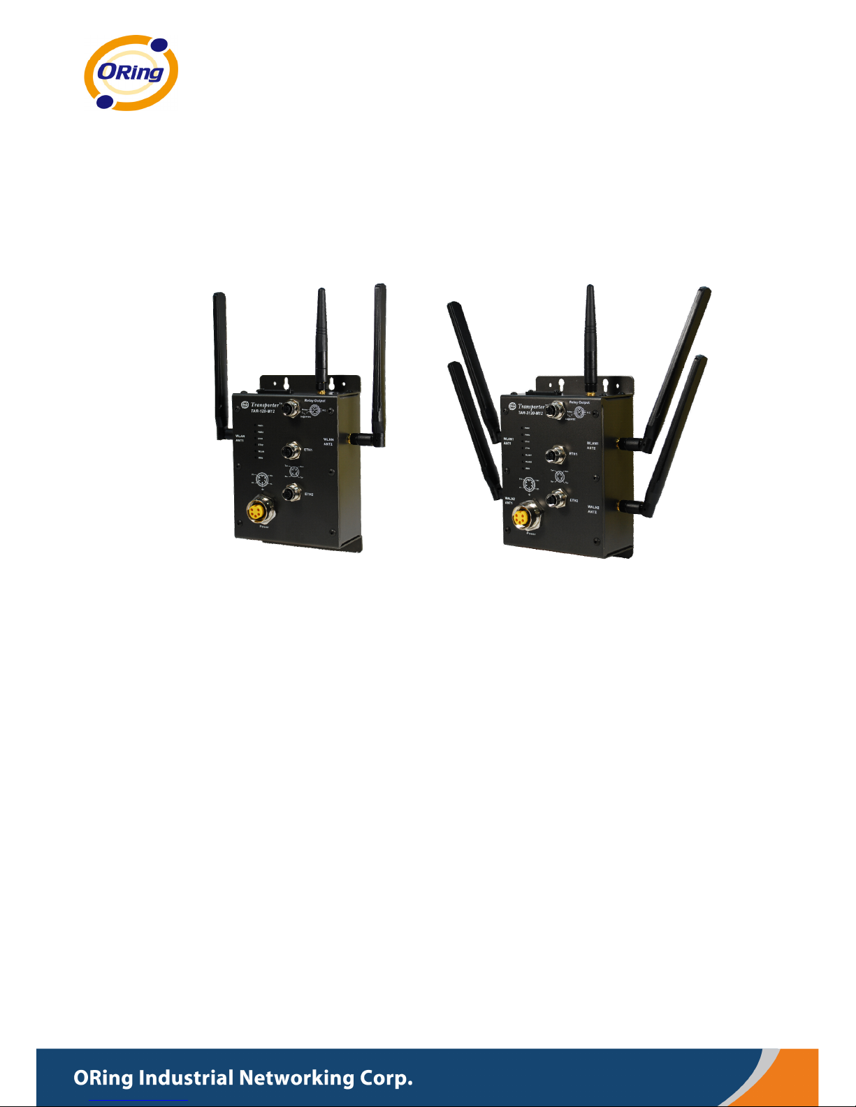
1.1 Overview
The ORing TAR-120-M12 / TAR-3120-M12
Wireless AP router is designed to operate in
industrial environments. The AP router provides
fast and effective ways of communicating to the
internet over wired or wireless LAN. In addition,
multiple kinds of WAN connections are provided
for easily access to the internet.
The ORing TAR-120-M12 / TAR-3120-M12 wireless AP router comes with IEEE
802.11a/b/g or IEEE 802.11b/g high-performance wireless technologies. It is capable of
data transfer rates up to 54Mbps. It is easy for you to extend the network reach and
increase the number of computers connected to your wireless network.
With built-in HSUPA WAN connection, the ORing TAR-120-M12 / TAR-3120-M12
wireless AP router can be mounted in harsh environment easily to provide internet access
anytime and anywhere.
The ORing TAR-120-M12 / TAR-3120-M12 wireless AP router's VPN capability creates
encrypted "Virtual Tunnels" through the internet, allowing remote or traveling users for
secured connection with the network in your office.
1.2 Software Features
High Speed Air Connectivity: WLAN interface supports up to 54Mbps link speed
connection
Highly Security Capability: WEP/WPA/WPA2/Radius/TKIP supported
Secured Management by HTTPS
Intuitive Web-based management user interface for simply and easily operation
Functions of firewall provides many security features such as blocking attacks from
hacker, especially IP Spoofing, Ping flood, Ping of Death, DOS, DRDOS, Stealth Scan,
ICMP flooding etc.
Advanced firewall configuration to extend the capability and security, such as Virtual
Server, Port Trigger, DMZ host, UPnP auto Forwarding, IP Filter and MAC filter

TAR-120-M12 / TAR-3120-M12 User’s Manual
ORing Industrial Networking Corp. 2
Switch Mode Supported: Daisy Chain support to reduce usage of switch ports
Event Warning by Syslog, Email, SNMP Trap, Relay and Beeper
1.3 Hardware Features
Built-in HSUPA Cellular Modem with SIM card slot included for WAN connection
Two 10/100Base-T(X) Ethernet ports for WAN / LAN connection individually
Redundant Power Inputs: Dual 12~48 VDC on M23 connector
Casing: IP-40
Dimensions (W x D x H) :
125(W) x 65(D) x 196(H) mm
Operating Temperature: -20 to 70
o
C
Storage Temperature: -40 to 85
o
C
Operating Humidity: 5% to 95%, non-condensing
TAR-120-M12 / TAR-3120-M12 User’s Manual
ORing Industrial Networking Corp. 3
Hardware Installation
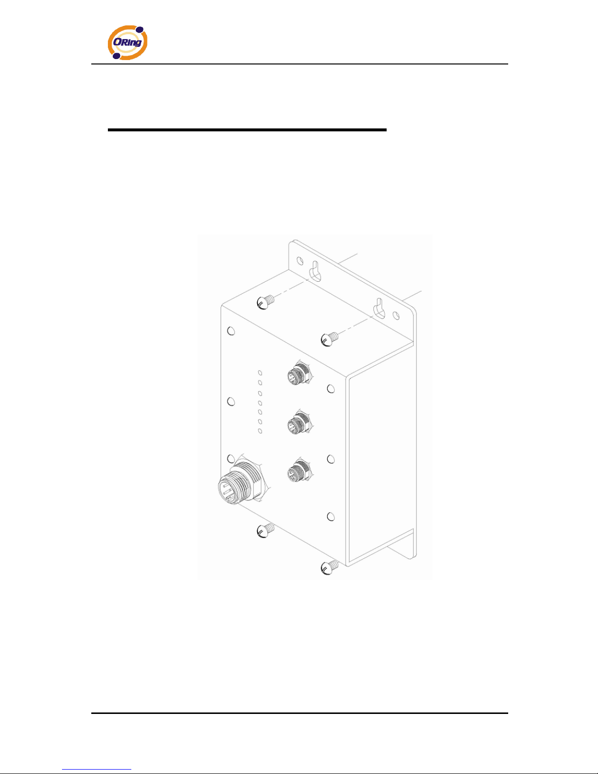
2.1 Wall Mounting Installation
Each AP router can be fixed on the wall. Use screws to mount the AP router on the
wall:
TAR-120-M12 / TAR-3120-M12 User’s Manual
ORing Industrial Networking Corp. 4
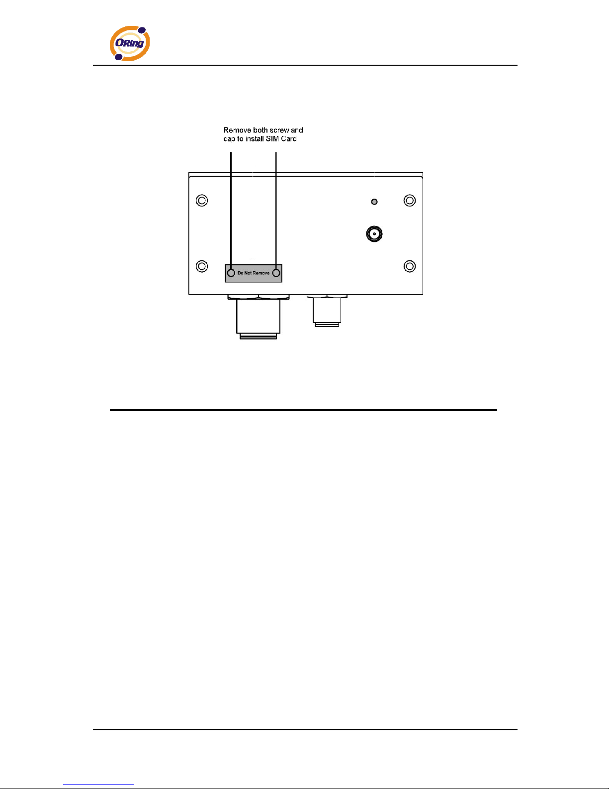
2.2 SIM Card Installation
Important Notice: POWER DOWN THE TAR-120-M12 / TAR-3120-M12 BEFORE
INSTALLING THE SIM CARD.
.
TAR-120-M12 / TAR-3120-M12 User’s Manual
ORing Industrial Networking Corp. 5
Hardware Overview
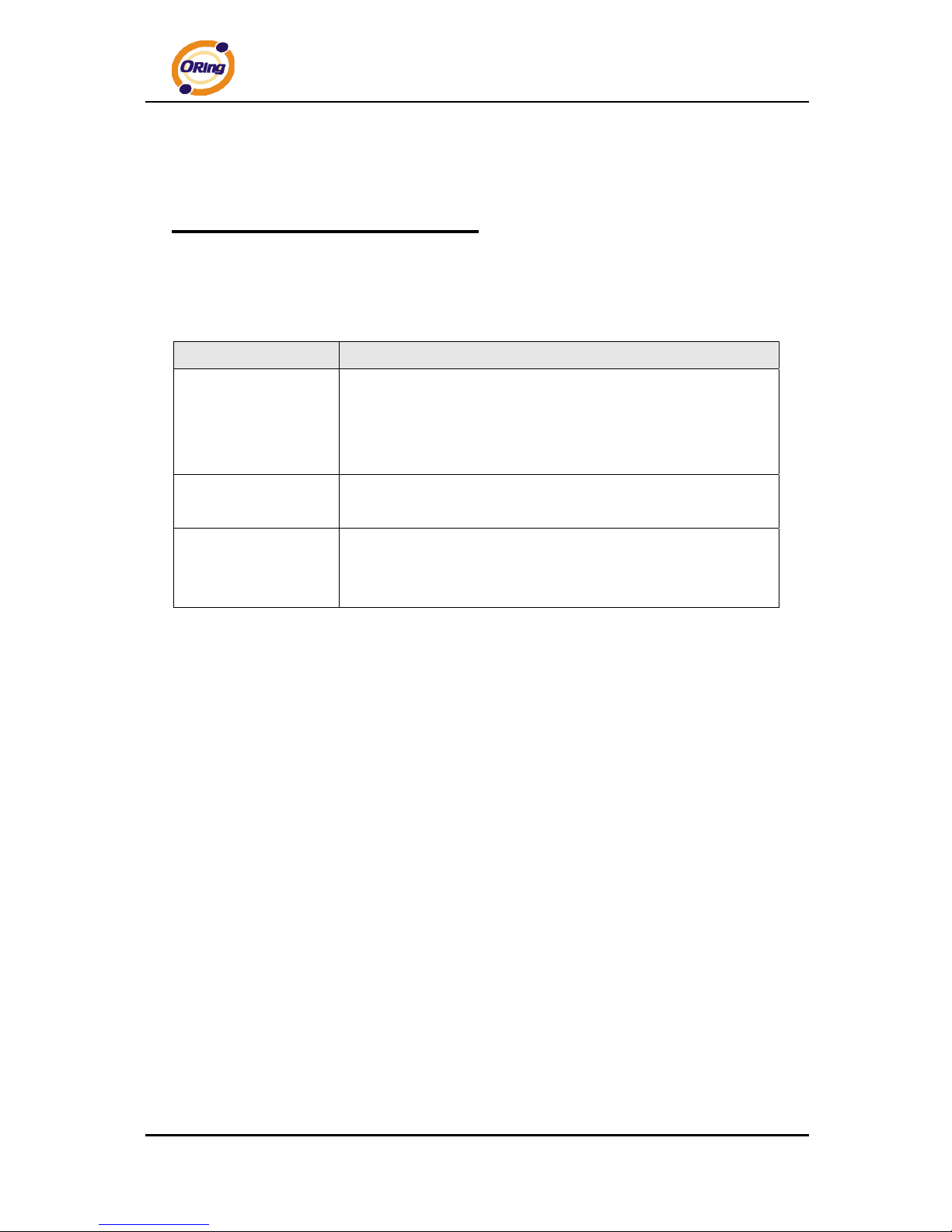
3.1 Front Panel
The following table describes the labels that stick on the TAR-120-M12 / TAR-3120-M12.
Port Description
10/100 Base-T(X) fast
Ethernet ports on
M12 connector
(D-coding)
2 10/100Base-T(X) fast Ethernet ports support auto-negotiation.
Default Setting :
Speed: auto
Relay Output on M12
(A-coding) connector
Relay output to carry capacity of 3A at 24VDC
Redundant power
inputs on M23
connector
Dual Power Inputs. 12~48 VDC on M23 connector (24 VDC Typ)

TAR-120-M12 / TAR-3120-M12 User’s Manual
ORing Industrial Networking Corp. 6
TAR-120-M12 / TAR-3120-M12

TAR-120-M12 / TAR-3120-M12 User’s Manual
ORing Industrial Networking Corp. 7
1. 2.4/5.8GHz antenna with typical 3.0 dBi antenna for IEEE 802.11a mode and 2 dBi for
IEEE 802.11b/g mode
2. LED for PWR1 and system status. When PWR1 links, the green LED will light On.
3. LED for PWR2 and system status. When PWR2 links, the green LED will light On.
4. LED for Ethernet port1 status.
5. LED for Ethernet port2 status.
6. LED for WLAN link status.
7. LED for internal HSUPA modem connection
8. LED for Fault Relay. When the fault occurs, the red LED will light On.
9. Power Input port on M23 connector
10. 2.4/5.8GHz antenna for WLAN2 of TAR-3120-M12 (TAR-3120-M12 only)
11. Ethernet port1 on M12(D-coding) connector
12. Ethernet port2 on M12(D-coding) connector
13. Relay output on M12(A-coding) connector
14. 850/900/1800/2100MHz antenna for internal HSUPA modem
15. HSUPA Cellular Modem with SIM card slot
3.2 Front Panel LEDs
LED Color Status Description
PWR1
Green/Red
Green On DC power 1 activated.
Green blinking Device been located
Red blinking
Indicates an IP conflict, or
DHCP or BOOTP server did
not respond properly
PWR2
Green/Red
Green On
DC power 2 activated.
Green blinking Device been located
Red blinking
Indicates an IP conflict, or
DHCP or BOOTP server did
not respond properly
ETH1
Amber
On Port link up at 10Mbps.
Blinking Data transmitted.
Green
On Port link up at 100Mbps.
Blinking Data transmitted.
ETH2
Amber
On Port link up at 10Mbps.
Blinking Data transmitted.
Green On Port link up at 100Mbps.

TAR-120-M12 / TAR-3120-M12 User’s Manual
ORing Industrial Networking Corp. 8
Blinking Data transmitted.
WLAN
Green
On WLAN1 activated.
Blinking WLAN1 Data transmitted.
Red(TAR-3120-M12
only)
On WLAN2 activated.
Blinking WLAN2 Data transmitted.
WAN
Green
On Modem Ready
Blinking Checking Modem status
Fault
Red On
Fault relay. Power failure or
Port down/fail.
TAR-120-M12 / TAR-3120-M12 User’s Manual
ORing Industrial Networking Corp. 9
Cables and Antenna
4.1 Ethernet Cables
The TAR-120-M12 / TAR-3120-M12 WLAN AP router has two 10/100Base-T(X)
Ethernet ports. According to the link type, the AP use CAT 3, 4, 5,5e UTP cables to
connect to any other network device (PCs, servers, switches, routers, or hubs). Please
refer to the following table for cable specifications.
Cable Types and Specifications
Cable Type Max. Length Connector
10Base-T Cat. 3, 4, 5 100-ohm UTP 100 m (328 ft) M12(D-coding)
100Base-T(X) Cat. 5 100-ohm UTP UTP 100 m (328 ft) M12(D-coding)
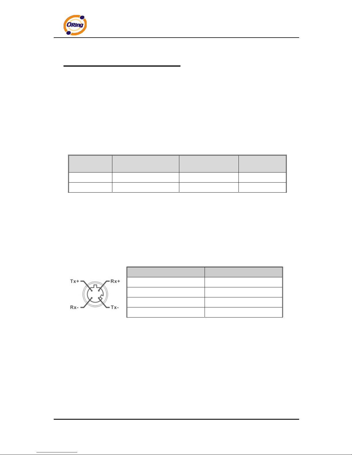
4.2 100BASE-TX/10BASE-T Pin Assignments
With 100Base-T(X)/10Base-T cable, pins 1 and 2 are used for transmitting data, and
pins 3 and 6 are used for receiving data.
M12(4-pin, D-coding) Pin Assignments
Pin Number Assignment
1 RD+
2 TD+
3 RD-
4 TD-
The TAR-120-M12 / TAR-3120-M12 supports auto MDI/MDI-X operation. You can use a
straight-through cable to connect PC and AP. The following table below shows the
10Base-T/ 100Base-T(X) MDI and MDI-X port pin outs.
TAR-120-M12 / TAR-3120-M12 User’s Manual
ORing Industrial Networking Corp. 10
MDI/MDI-X pins assignment
Pin Number MDI port MDI-X port
1 RD+(receive) TD+(transmit)
2 TD+(transmit) RD+(receive)
3 RD-(receive) TD-(transmit)
4 TD-(transmit) RD-(receive)
Note: “+” and “-” signs represent the polarity of the wires that make up each wire pair.
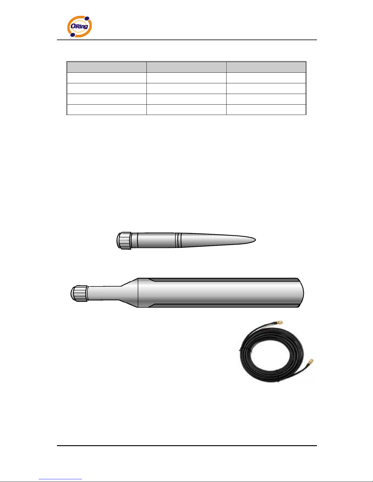
4.3 Wireless Antenna
2.4GHz/5.8GHz antenna is used for the WLAN interface of TAR120-M12 / TAR-3120-M12
and connected with a reversed SMA connector. 850/900/1800/2100MHz antenna is used
for built-in HSUPA modem. External RF cable and antenna also can be applied with this
connector.
Cellular Antenna
WLAN Antenna
WLAN Antenna
TAR-120-M12 / TAR-3120-M12 User’s Manual
ORing Industrial Networking Corp. 11
Management Interface
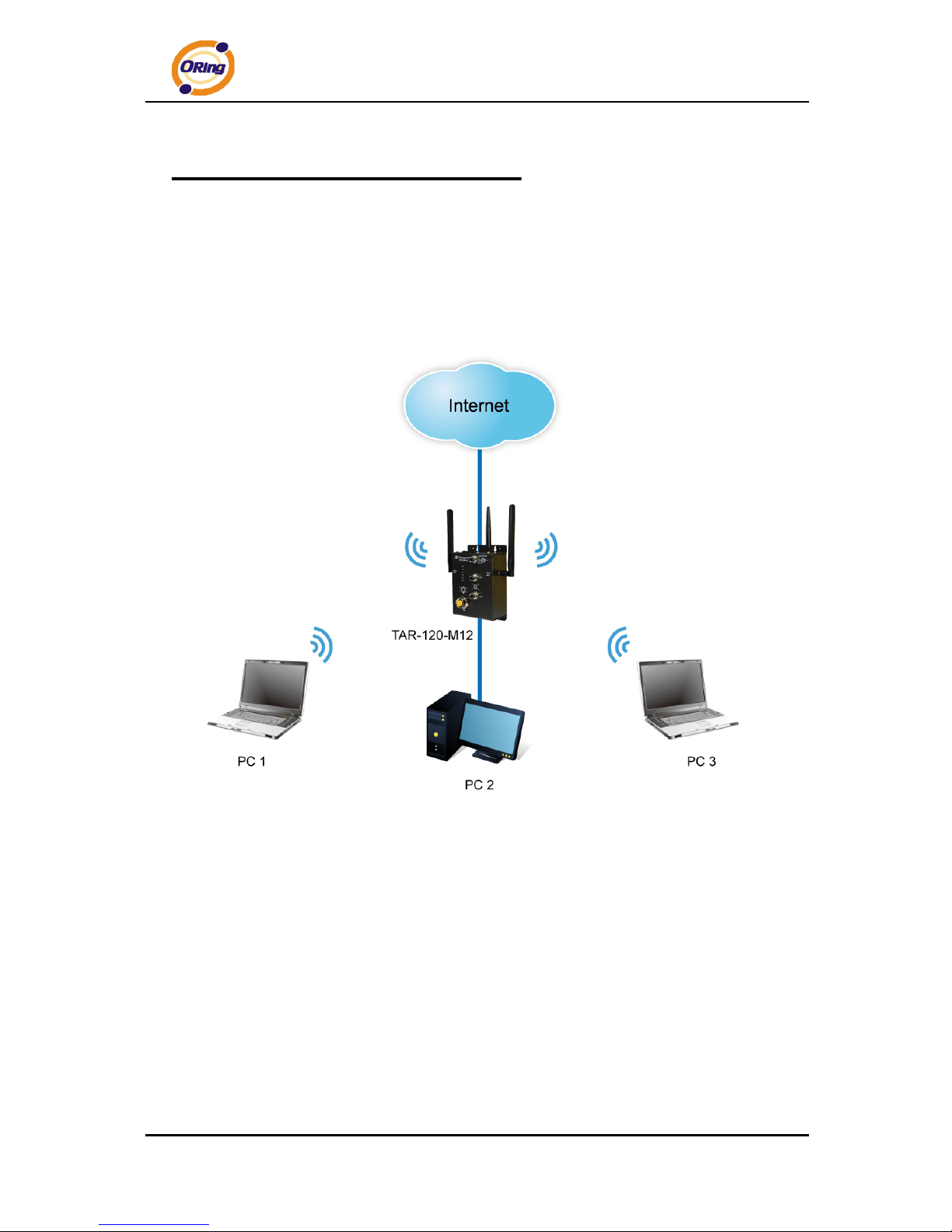
5.1 First-time Installation
Before installing the TAR-120-M12 / TAR-3120-M12 WLAN AP router, you need to
access WLAN AP router with a computer via wired LAN connection or wireless LAN
interface. Using wired LAN connection is much easier and is highly recommended.
Basic connection for TAR-120-M12 / TAR-3120-M12
Step 1: Select the Power Source
TAR-120-M12 / TAR-3120-M12 AP router can be powered by +12~48V DC power input.
Step 2: Connect a computer to TAR-120-M12 / TAR-3120-M12
Use an appropriate Ethernet cable (e.g. RJ-45 to M12) to connect the ETH2 port of
TAR-120-M12 / TAR-3120-M12 AP router to the LAN port of a computer. If the LED of
the LAN port lights up, it indicates that the connection is established. After that, the
computer will initiate a DHCP request to get an IP address from the AP router.
TAR-120-M12 / TAR-3120-M12 User’s Manual
ORing Industrial Networking Corp. 12
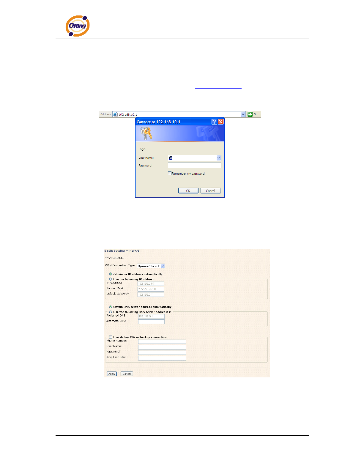
Step 3: Use the web-based manager to configure TAR-120-M12 / TAR-3120-M12
The default gateway IP of TAR-120-M12 / TAR-3120-M12 AP router is 192.168.10.1.
Start the web browser of your computer and type http://192.168.10.1
in the address box to
access the webpage. A login window will popup, and then enter the default login name
admin and password admin.
Login screen
Step 4: Select WAN connection type
Click the Basic Setting in the top menu to enter the WAN configuration page. Select
the proper connection type according to the information of your ISP.
WAN connection type
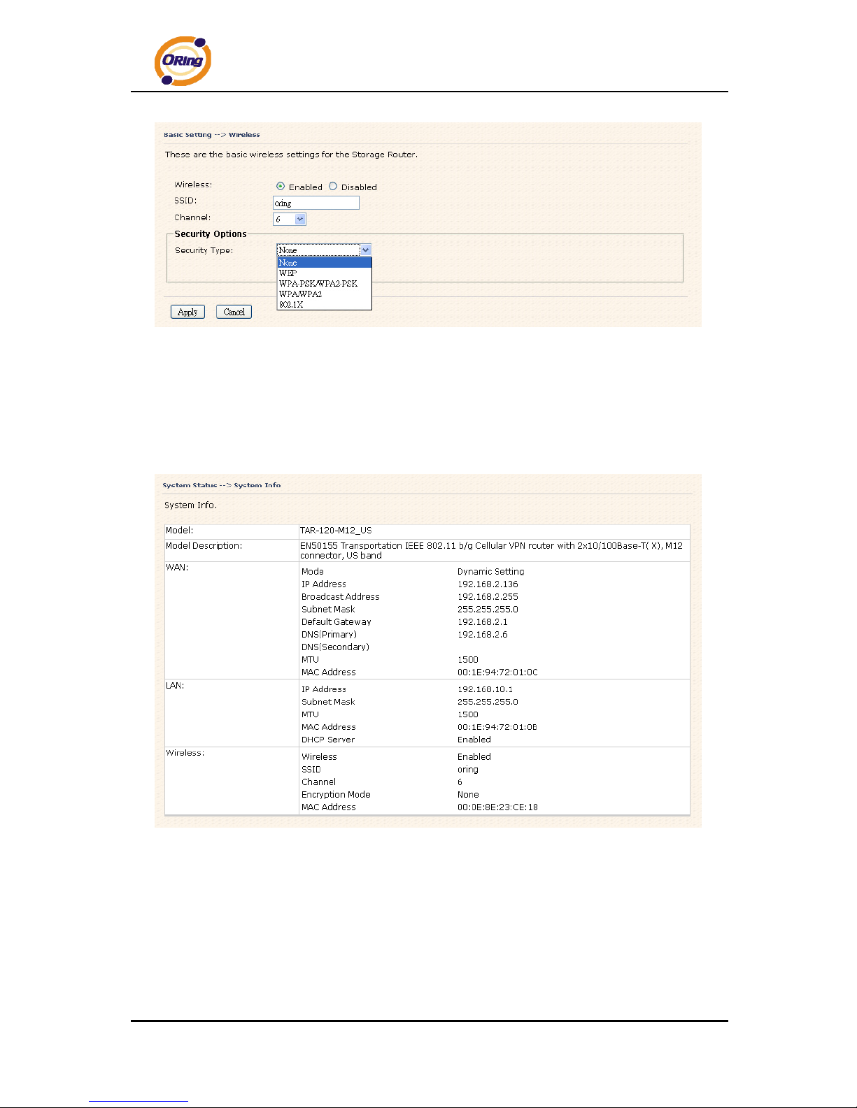
Step 5: Protect the wireless access in encryption mode
Click Wireless in Basic Setting menu. The default encryption mode is None. Choose
WEP/WPA to enhance the security of wireless connection.
TAR-120-M12 / TAR-3120-M12 User’s Manual
ORing Industrial Networking Corp. 13
Wireless security option
Step 6: Review the router settings and check router status
Click the System Status in the top of the menu, the system info page will be shown.
You can check all the configuration and status of the router.
System status Screen
TAR-120-M12 / TAR-3120-M12 User’s Manual
ORing Industrial Networking Corp. 14
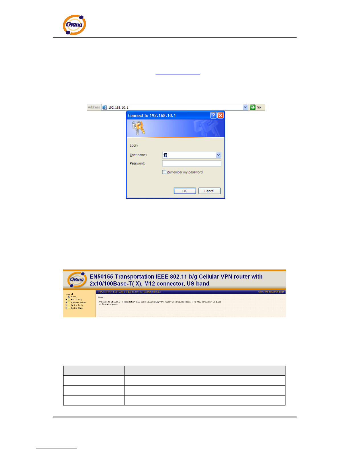
5.2 Configure the Wireless Router
In this section, the web management page will be explained in detail.
With default setting, you can type http://192.168.10.1
in the address box of web browser
to login the web management interface. A login window will be prompted, enter username
admin & password admin to login.
Login screen
For security reasons, we strongly recommend you to change the password. Click on
System Tools > Login Setting and change the password.
5.3 Main Interface
The Home screen will be shown when login successfully.
Main Interface
In the page, you can check the Firmware version, the router running time and the WAN
IP setting.
The following table describes the labels in this screen.
Label Description
Firmware
Show the current firmware version.
Uptime
Show the elapsed time since the AP router is started.
Wan IP
Show the WAN IP address.
 Loading...