

ORiNG RGS-R9244GP+, RGS-R9244GP+-E Quick Installation Manual
G2 G4 G6 G8
G1 G3 G5 G7
LINK/ACT
Console
G25 G26 G27 G28
RGS-R9244GP+
R.M.
Ring
Reset
10/100/
1000T
Fault
10GSFP+
G10 G12 G14 G16
G9 G11 G13 G15
G18 G20 G22
G17 G19 G21 G23
G24
PWR
Quick InstallationGuide
Version 1.2
Quick Installation Guide
Introduction
PRINTED ON RECYCLED PAPER
QIG
RGS-R9244GP+ Series
1907-2-29-RGSR9244GP+-1.2
The which consistof , and
are rack-mountEthernet switches withtwenty-four
10/100/1000BaseT(X) Ethernetports and four1G/10G SFP+ ports.The
device providesLayer 3 functionssuch as RIP, VRRP, andstatic routing for
more efficientnetwork management andhigher security.The
is anenhanced model withdual DC inputsand relay output.
With completesupport for Ethernetredundancy protocols suchas O-Ring
(recovery time< 30ms over250 units ofconnection), O-Chain, MRP, Fast
Recovery,and MSTP (RSTP/STPcompatible), the switchcan protect your
mission-critical applicationsfrom network interruptionsor temporary
malfunctions withits fast recoverytechnology. Featuringa wide operating
temperature from-20 C to 60 C,the device canbe managed centrallyand
conveniently viaOpen-Vision utility,web browsers, Telnet andconsole
(CLI) configuration,making it tobe one ofthe most reliablechoice for
highly-managed andFiber Ethernet application.
RGS-R9244GP+ series RGS-R9244+ RGS-
R9244GP+-E,
RGS-
R9244GP+-E
oo
Preparation
Before youbegin installing theswitch, make sureyou have allof the package
contents availableand a PCwith Microsoft InternetExplorer 6.0 orlater, for
using web-basedsystem management tools.
Elevated OperatingAmbient: If installed in a closed or multi-unit rack
assembly,the operating ambienttemperature of therack environment maybe
greater thanroom ambient. Therefore,consideration should begiven to
installing theequipment in anenvironment compatible withthe maximum
ambient temperature(Tma) specified bythe manufacturer.
Safety & Warnings
Dimension
Panel Layouts
1. Consoleport
2. Resetbutton
3. Powerindicator
4. Ringstatus LED
5. RMstatus LED
6. Faultindicator
Front View
Rear View
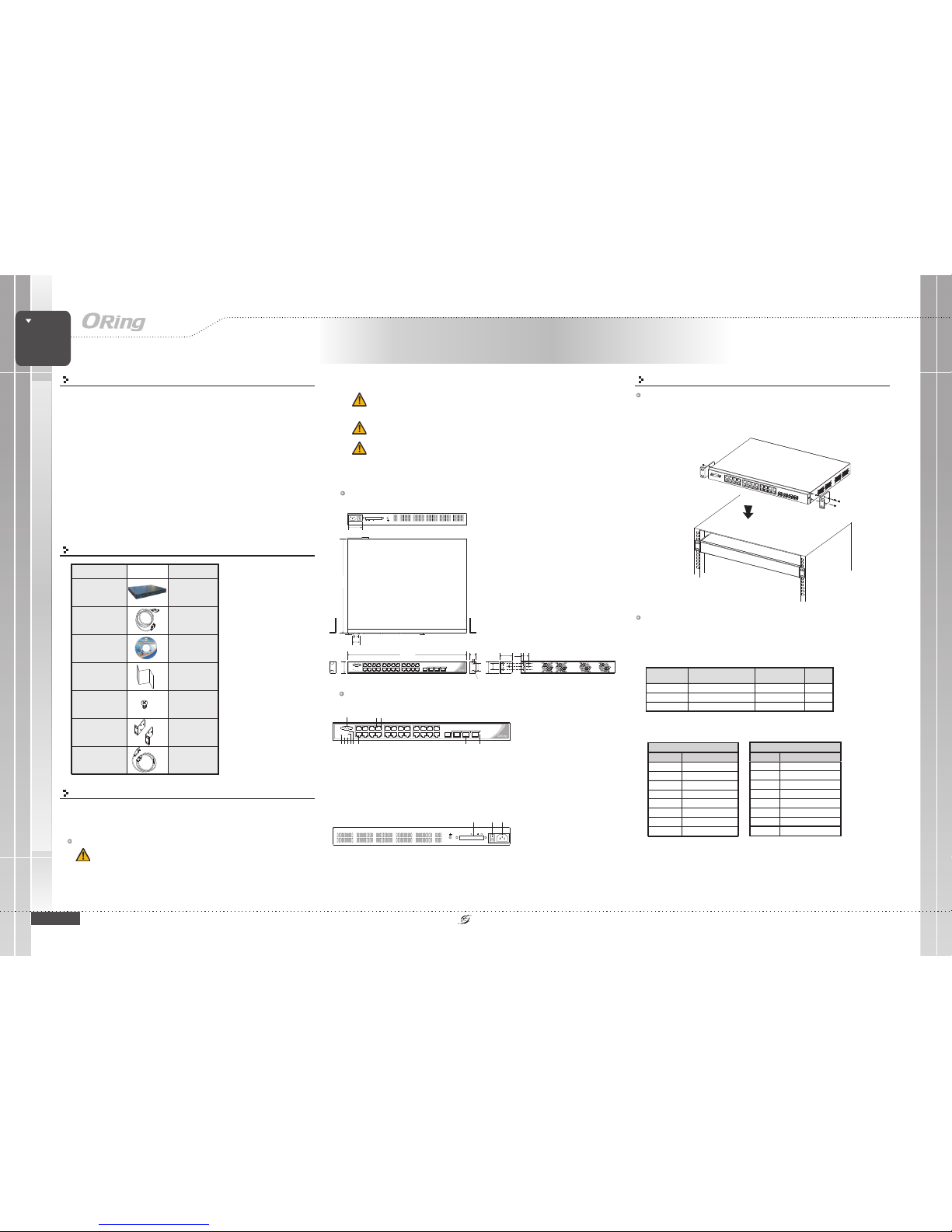
Package Contents
Contents
QIG
CD
Console Cable
Screw (M4X6)
Powercord
Rack-mounted
kit(L&R)
Number
X1
X1
X1
X6
X1
X1
RGS-R9244GP+ or
RGS-R9244GP+-E
Pictures
X1
35.50
44.00
8.00
20.00
24.00
32.0
5.50
R3.25
25.50
2.50
4.30
17.80
30.20
342.00
3.0
44.00
431.00
G2 G4 G6 G8
G1 G3 G5 G7
LINK/ACT
Console
G25 G26 G27 G28
RGS-R9244GP+
R.M.
Ring
Reset
10/100/
1000T
Fault
10GSFP+
G10 G12 G14 G16
G9 G11 G13 G15
G18 G20 G22
G17 G19 G21 G23
G24
PWR
1
2 3 4 5 6 7
8 9
10 11
7. LANports
8. LEDfor Ethernet portsLNK/ACT status
9. LEDfor Ethernet portsspeed indicator
10. SFP+ports
11. LNK/ACTLED for SFP+ports
1 2
1. Powerswitch
2. ACpower input (100V~240V
/ 50~60Hz)
3. DualDC power inputs
(RGS-R9244GP+-E Only)
MANAGED
Rack-Mount
GIGABIT
SWITCH
ReducedAir Flow:
Mechanical Loading:
Circuit Overloading:
Installation of the equipment in a rack should be such that the
amount of air flow required for safe operation of the equipment is not
compromised.
Mounting of the equipment in the rack should be such that a
hazardous condition is not achieved due to uneven mechanical loading.
Consideration shouldbe given tothe connection ofthe equipment
to thesupply circuit andthe effect thatoverloading of thecircuits might haveon
overcurrent protectionand supply wiring.Appropriate considerationof equipment
nameplate ratingsshould be used when addressingthis concern.
Network Connection
The serieshave standard Ethernetports. Accordingto the linktype, the switchuses CAT3, 4,
5,5e UTPcables to connectto any othernetwork devices (PCs,servers, switches, routers,or
hubs). Pleaserefer to thefollowing table forcable specifications.
Cable Typesand Specifications:
Cable Type Max. Length Conn ector
10BASE-T Cat. 3, 4,5 100-ohm UTP 100m (328 ft) RJ-45
100BASE-TX Cat.5 100-ohmUTP UTP100 m(328 ft) RJ-45
1000BASE- T Cat. 5 /Cat. 5e 100-ohm UTP UTP100 m (328 ft) RJ-4 5
Installation
Rack-mounting
Step 1:
Step 2:
Install leftand right frontmounting brackets tothe switch usingthree screws on each side.
With frontbrackets orientated infront of therack, fasten thebrackets to therack using two
more screws.
Layer-3 Managed Gigabit Ethernet
Switch
For pinassignments for differenttypes of cables,please refer tothe following tables.
1000Base- TRJ-45
Pin Number Assignment
1BI_DA+
2BI_DA-
3BI_DB+
4BI_DC+
5BI_DC-
6BI_DB-
7BI_DD+
8BI_DD-
10/100Base-T(X)RJ-45
Pin Numbe r Assignment
1TD+
2TD-
3RD+
4Notused
5Notused
6RD-
7Notused
8Notused
RGS-R9244GP+ Series
49.0
AC100-240V50-60Hz
PW3
V+ V-
PW2
1A@24V
DCPower
12V~48V
AC100-240V50-60Hz
PW3
V+ V-
PW2
1A@24V
DCPower
12V~48V
3
QIG
Quick InstallationGuide
PRINTED ON RECYCLED PAPER
Version 1.2
Quick Installation Guide
ORing IndustrialNetworking Corp.
Copyright© 2015 ORing
All rightsreserved.
TEL: +886-2-2218-1066
FAX:+886-2-2218-1014
Website: www.oring-networking.com
E-mail: support@oring-networking.com
RGS-R9244GP+ Series
MANAGED
Rack-Mount
GIGABIT
SWITCH
Layer-3 Managed Gigabit Ethernet
Switch
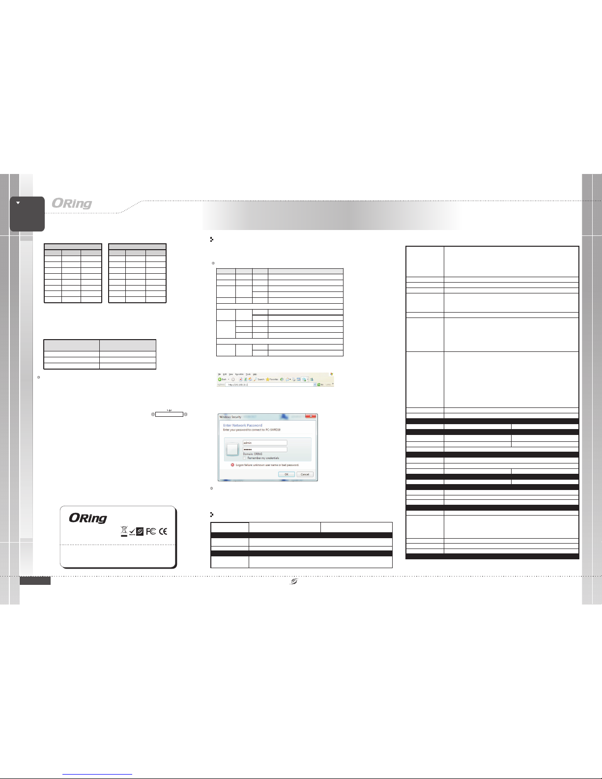
1. Launchthe Internet Explorerand type inIP address ofthe switch.The default staticIP address is
192.168.10.1
2. Login with defaultuser name andpassword (both are ). Afterlogging in, you should see
the following screen. For more information on configurations, please referto the usermanual.
For informationon operating theswitch using ORing’sOpen-Vision management utility, pleasego to
ORing website.
admin
Resetting
Toreboot the switch,press the button for5 seconds.
Torestore the switchconfigurations back tothe factory defaults,press the buttonfor 10 seconds.
Reset
Reset
Specifications
ORingSwitch Model
PhysicalPorts
Technology
EthernetStandards
10/100/1000Base-T(X)with
RJ45Auto MDI/MDIX
RS-232Serial Console Port
SwitchProperties
SecurityFeatures
DeviceBinding security feature
Enable/disableports, MAC basedport security
Portbased network accesscontrol (802.1x)
MAC-basedauthentication
MACaddresslimit
VLAN(802.1Q) to segregatean secure networktraffic
Radiuscentralized password management
SNMPv3encrypted authentication andaccess security
Https/ SSH enhancenetwork security
Weband CLI authenticationand authorization
IPsource guard
SoftwareFeatures
Hardwarerouting, RIP andstatic routing
IEEE802.1D Bridge, autoMAC address learning/agingand MAC address(static)
MultipleRegistration Protocol (MRP)
MSTP RSTP/STP compatible)
RedundantRing (O-Ring) withrecovery time lessthan 30ms over250 units
TOS/Diffservsupported
Qualityof Service (802.1p)for real-time traffic
VLAN(802.1Q) with VLANtagging
IGMPv2/v3 Snooping
IP-basedbandwidth management
Application-basedQoS management
DOS/DDOSauto prevention
Portconfiguration, status, statistics,monitoring, security
DHCPServer/Client
DHCPRelay
ModbusTCP
DNSclient proxy
SMTPClient
NTPserver
(
NetworkRedundancy
O-Ring,O-Chain, MRP,MSTP (RST/STP compatible),Fast Recovery
RS-232in DB-9 connectorwith console cable. 115200bps, 8, N, 1
RGS-R9244GP+
24
IEEE802.3ab for 1000Base-T
IEEE802.3ae for 10GigabitEthernet
IEEE802.3x for Flowcontrol
IEEE802.3ad for LACP(Link Aggregation ControlProtocol )
IEEE802.1p for COS(Class of Service)
IEEE802.1Q for VLANTagging
IEEE802.1w for RSTP(Rapid Spanning TreeProtocol)
IEEE802.1s for MSTP(Multiple Spanning TreeProtocol)
IEEE802.1x for Authentication
IEEE802.1AB for LLDP(Link Layer DiscoveryProtocol)
Switchlatency: 7 us
Switchbandwidth: 128Gbps
Max.Number of AvailableVLANs: 4095
VLANID Range: VID1 to 4094
IGMPmulticast groups: 128for each VLAN
Portrate limiting: UserDefine
MACTable
32K
Processing
Store-and-Forward
PriorityQueues
8
Jumboframe Upto 10K Bytes
Power
Powerconsumption(Typ.)
37.4Watts
Overloadcurrent protection
Present
Powerinput
100~240VACwith power socket
1G/10GBase-Xwith SFP+ port
4
Environmental
-40to85C(-40to185F)
oo
StorageTemperature
OperatingTemperature
PhysicalCharacteristic
Dimension(WxDxH)
Weight (g)
4597g
5%to 95% Non-condensing
OperatingHumidity
Enclosure
19inches rack mountable
431(W)x342(D)x44(H)mm(16.97x13.47x1.73inches)
-20to60C(-4to140F)
oo
RegulatoryApprovals
FCCPart 15, CISPR(EN55022) class AEMI
EN61000-4-2(ESD)
EN61000-4-3(RS)
EN61000-4-4(EFT)
EN61000-4-5(Surge)
EN61000-4-6(CS)
EN61000-4-8
EN61000-4-11
EMS
Warranty
5years
Warranty
5years
IEC60068-2-27Shock
IEC60068-2-32FreeFall
IEC60068-2-6Vibration
FaultContact
Relay
None
Wiring
462,867hrsTime
10/100Base-T(X)MDI/MDI- X
Pin Number MDI port MDI-X port
1TD+(transmit)RD+(receive)
2TD-(transmit)RD-(receive)
3 RD+(receive) TD+(transmit)
4NotusedNotused
5NotusedNotused
6 RD-(receive) TD-(transmit)
7NotusedNotused
8NotusedNotused
1000Base-T MDI/MDI-X
Pin Number MDIport MDI-X port
1 BI_DA+ BI_DB+
2 BI_DA- BI_DB-
3 BI_DB+ BI_DA+
4 BI_DC+ BI_DD+
5 BI_DC- BI_DD-
6 BI_DB- BI_DA-
7 BI_DD+ BI_DC+
8 BI_DD- BI_DC-
Note: “+”and “-” signsrepresent the polarityof the wiresthat make up
each wirepair.
Toconnect the consoleport to anexternal management device,you need anDB-9
cable, whichis also suppliedin the package.Below is theconsole port pinassignment
information.
Console PortPin Definition
PC RS-232 to D B9 (male) pi n
assignment
RS-232 with DB9 (female) pin
assignment
PIN#2 RxD PIN#2 RxD
PIN#3 TxD PIN# 3 TxD
PIN#5 G ND PIN#5 G ND
AC PowerConnection
Both RGS-R9244GP+and RGS-R9244GP+-E canbe powered byAC electricity.Simply
insert the AC power cable to the power connector at the back of the switch and
turn on the power switch. The input voltage is 100V~240V /50~60Hz.
DC PowerConnection
The RGS-R9244GP+-Esupports dual DCpower supplies,
Power Supply2 (PWR2) andPower Supply 3(PWR3). The
connections forPWR1, PWR2 andthe RELAYare located on
the terminalblock. The inputvoltage is 36V~72VDC.
STEP 1:
STEP 2:
Insert the negative/positive wires into the V-/V+ terminals, respectively.
To keep the DC wires from pulling loose, use a small flat-blade
screwdriver totighten the wire-clampscrews on thefront of theterminal block
connector.
Relay contact
Grounding
The RGS-R9244GP+-Eprovides two setsof relay contactson the 6-pin terminal block
to detectuser-configured events. Thetwo wires attachedto the faultcontacts form an
open circuitwhen a user-configuredwhen an eventis triggered. Ifa user-configured
event doesnot occur,the fault circuitremains closed.
Grounding andwire routing to help limit theeffects of noisedue to electromagnetic
interference (EMI).Run the groundconnection from theground screws tothe grounding
surface priorto connecting devices.
V+ V- V- V+
1A@24V
DCPower 36~72V
PW2 PW3
EthernetStandards
IEEE802.3 for 10Base-T
IEEE802.3u for 100Base-TX
IEEE802.z for 1000Base-X
Configurations
After installingthe switch andconnecting cables, startthe switch byturning on power.
The greenpower LED shouldturn on.
LED indication table
LED Color Status Descripti on
PWR Green On System power is co nnected
R.M Green On D evice is operat ing as a rin g master
On R ing is enabl ed and device is runni ng in Ring mo de
Ring Green
Blinking Ring struct ure is broken
Fault Amber On E rrors (power f ailure or po rt malfuncti oning)
10/100/1000Base -T(X) RJ45 por t
On P ort is connec ted
LNK/ACT Green
Blinking Transmitting data
Amber On Port is runni ng at 100Mbps
Green On Port is run ning at 100 0MbpsSpeed
Off Port is runnin g at 10Mbps
1G/10G SFP+ por t
On P ort is connec ted
LNK/ACT Green
Blinking Transmitting data
RGS-R9244GP+-E
100~240VACwith power socket,dual 36~72VDC power
input
37.4Watts
4754g
MTBF(meantime between failures)
371,822hrs
RGS-R9244GP+ Series
Present
 Loading...