

ORiNG RGS-92222GCP-NP Installation Manual
35.50
44.00
8.00
20.00
24.00
32.0
5.50
R3.25
25.50
2.50
4.30
17.80
30.20 82.00
342.00
58.8
ACPowerSWITCH
49.0
3.0
AC100-240V
50-60HZ
PW1
44.00
431.00
G2 G4 G6 G8
G1 G3 G5 G7
LINK/ACT
Console
RGPS-92222GCP-NP-E
R.M.
Ring
Reset
10/100/
1000T
Fault
100/1000X
G10 G12 G14 G16
G9 G11 G13 G15
G18 G20 G22
G17 G19 G21 G23
G24
PW1
14.2
Quick InstallationGuide
Version 1.0
Quick Installation Guide
Introduction
PRINTED ON RECYCLED PAPER
RGS-92222GCP-NP Series
QIG
RGS-92222GCP-NP Series
1907-2-29-RGS92222GCPNP-1.0
The which consistof , and
, are managed Ethernet switches designed for
industrial applications. uring 2210/100/1000Base-T(X) ports, 2
Gigabit combo ports and 2 100/1000Base-X SFP ports, the series is
able to meet the needs for highport density andhigh-speed, longdistance transmission.The is anenhanced model
with dualDC inputs andrelay output. Withcomplete support forEthernet
redundancy protocolssuch as O-Ring(recovery time <30ms over 250units
of connection)and MSTP (RSTP/STPcompatible), the seriescan protect
your mission-criticalapplications from networkinterruptions or temporary
malfunctions withits fast recoverytechnology. Featuringa wide operating
temperature from-40 C to 75 C, thedevice can bemanaged centrally and
conveniently viaOpen-Vision, web browsers,Telnet andconsole (CLI)
configuration, makingit one ofthe most reliablechoice for highly-managed
and FiberEthernet power substationand rolling stockapplication.
RGS-92222GCP-NP series RGS-92222GCP-NP
RGS-92222GCP-NP-E
RGS-92222GCP-NP-E
Feat
oo
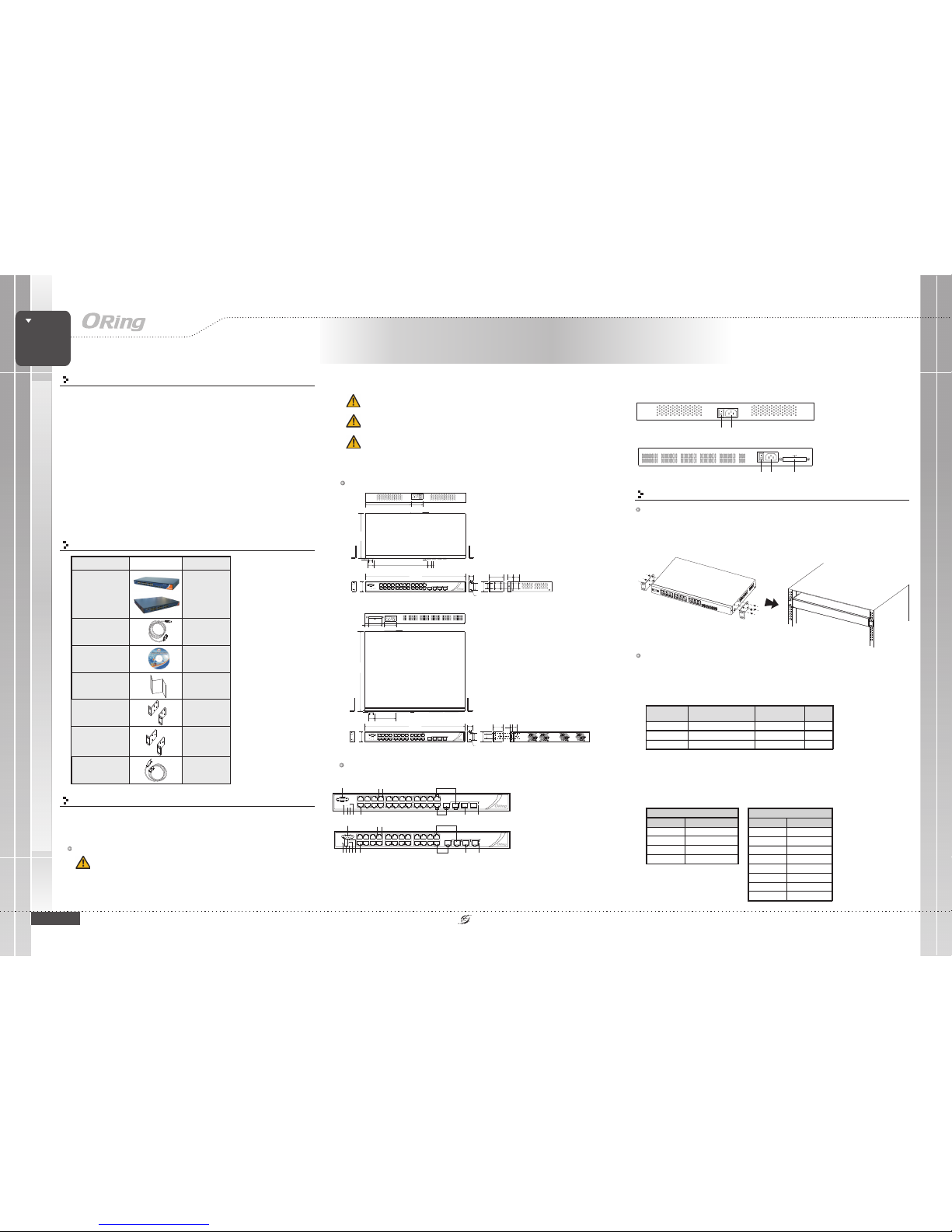
Dimension
Panel Layouts
1. Consoleport
2. Resetbutton
3. Powerindicator
4. Ringstatus LED
5. RMstatus LED
6. LANports
Front View
Rear View
Installation
Rack-mounting
Step 1:
Step 2:
Install leftand right frontmounting brackets tothe switch usingfour screws on each side.
With frontbrackets orientated infront of therack, fasten thebrackets to therack using two
more screws.
Network Connection
Package Contents
MANAGED
Rack-Mount
GIGABIT
SWITCH
Managed Gigabit Ethernet Switch
1
2 3 4 5 69
10
11 12
7. LEDfor Ethernet portslink/act status
8. LEDfor Ethernet portsSpeed indicator
9. FirstGigabit combo port
10. SecondGigabit combo port
11. SFPports
12. LNK/ACTLED for SFPports
13. Faultindicator
1 2
1. Powerswitch
2. ACpower input (100V~240V
/ 50~60Hz)
3. DualDC power inputs
The switchprovides standard Ethernet ports.According to thelink type, theswitch uses CAT
3,4,5,5e UTP cables to connect to any other network devices (PCs, servers, switches,
routers, or hubs). Please refer to the following table for cable specifications.
Cable Typesand Specifications:
Cable Type Max. Length Conn ector
10BASE-T Cat. 3, 4,5 1 00-ohm UTP 100 m (328 ft) RJ-45
100BASE-TX Cat. 5 100-ohmUTP UTP100 m (328ft) RJ-45
1000BASE- T Cat. 5 / Cat . 5e 100-o hm UTP UTP 100 m (3 28 ft) RJ-4 5
With 10/100BASE-T(X)cables, pins 1and 2 areused for transmittingdata, and pins3 and 6are
used forreceiving data. Thedevice also supportsauto MDI/MDI-X operation.You canuse a
cable toconnect the switchto a PC
For pinassignments for differenttypes of cables,please refer tothe following
tables.
Contents
QIG
CD
Console Cable
RGS-92222GCP-NP
or
RGS-92222GCP-NP-E
RGS-92222GCP-NP
Rack-mounted
kit(L&R)
Pictures Number
X1
X1
X1
X1
X1
Power Cable
X1
Preparation
Before youbegin installing theswitch, make sureyou have allof the package
contents availableand a PCwith Microsoft InternetExplorer 6.0 orlater, for
using web-basedsystem management tools.
Elevated OperatingAmbient: If installed in a closed or multi-unit rack
assembly,the operating ambienttemperature of therack environment maybe
greater thanroom ambient. Therefore,consideration should begiven to
installing theequipment in anenvironment compatible withthe maximum
ambient temperature(Tma) specified bythe manufacturer.
Safety & Warnings
ReducedAir Flow:
Mechanical Loading:
Circuit Overloading:
Installation of the equipment in a rack should be such that the
amount of air flow required for safe operation of the equipment is not compromised.
Mounting of the equipment in the rack should be such that a
hazardous condition is not achieved due to uneven mechanical loading.
Consideration shouldbe given tothe connection ofthe equipment to
the supplycircuit and theeffect that overloadingof the circuitsmight have onovercurrent
protection andsupply wiring.Appropriate consideration ofequipment nameplate ratings
should beused when addressing thisconcern.
44.00
443.70
58.00
42.70
26.70
24.00
24.00
30.20
3.90
R3.50
19.00
3.70
4.30
17.80
30.20 238.00
15.90
6.60
200.00
G2 G4 G6 G8
G1 G3 G5 G7 G9
G11
G13 G15
G10
G12
G14 G16
G17
G19
G21 G23
G18
G20
G22 G24
LINK/ACT
Console
10/100/
1000T
AC100-240V
50-60HZ
215.5 49.0
3.0
RGS-92222GCP-NP
Reset
R.M.
Ring
PWR
G23 G25 G26
100/1000X
AC100-240V
50-60HZ
G2 G4 G6 G8
G1 G3 G5 G7 G9
G11
G13 G15
G10
G12
G14 G16
G17
G19
G21 G23
G18
G20
G22 G24
LINK/ACT
Console
10/100/
1000T
RGS-92222GCP-NP
Reset
R.M.
Ring
PWR
G23 G24 G25 G26
100/1000X
7 8
10/100Base-T(X) RJ-45 port
PinNumber Assignment
#1 TD+
#2
TD-
#3
RD+
#6
RD-
1000Base-T RJ-45 port
PinNumber Assignment
#1 BI_DA+
#2
BI_DA-
#3
BI_DB+
#4
BI_DC+
#5
BI_DC-
#6
BI_DB-
#7
BI_DD+
#8
BI_DD-
RGS-92222GCP-NP-E
Rack-mounted
kit(L&R)
X1
RGS-92222GCP-NP
RGS-92222GCP-NP-E
G24
G23 G25 G26G24
PW2
PW3
G2 G4 G6 G8
G1 G3 G5 G7
LINK/ACT
Console
RGPS-92222GCP-NP-E
R.M.
Ring
Reset
10/100/
1000T
Fault
100/1000X
G10 G12 G14 G16
G9 G11 G13 G15
G18 G20 G22
G17 G19 G21 G23
G24
PW1
G23 G25 G26G24
PW2
PW3
1
2 3 45 6
9 11 1 2
7 8
10
13
RGS-92222GCP-NP-E
RGS-92222GCP-NP
ACPowerSWITCH
AC100-240V
50-60HZ
PW1
1 2 3
RGS-92222GCP-NP-E
RGS-92222GCP-NP
V+V- V- V+
3A@24V
DCPower48V
PW2 PW3
V+ V- V- V+
3A@24V
DCPower48V
PW2 PW3
QIG
Quick InstallationGuide
PRINTED ON RECYCLED PAPER
Version 1.0
Quick Installation Guide
Resetting
Toreboot the switch,press the button for5 seconds.
Torestore the switchconfigurations back tothe factory defaults,press the buttonfor 10
seconds.
Reset
Reset
Specifications
ORingSwitch Model
PhysicalPorts
Technology
EthernetStandards
10/100/1000Base-T(X)with
Portsin RJ45 AutoMDI/MDIX
SwitchProperties
SecurityFeatures
DeviceBinding security feature
Enable/disableports, MAC basedport security
Portbased network accesscontrol (802.1x)
Single802.1x and Multiple802.1x
MAC-basedauthentication
QoSassignment
GuestVLAN
MACaddresslimit
TACACS+
VLAN(802.1Q) to segregatean secure networktraffic
Radiuscentralized password management
SNMPv3encrypted authentication andaccess security
Https/ SSH enhancenetwork security
Weband CLI authenticationand authorization
Authorization(15 levels)
IPsource guard
22
IEEE802.3 for 10Base-T
IEEE802.3u for 100Base-TXand 100Base-FX,
IEEE802.3z for 1000Base-X,
IEEE802.3ab for 1000Base-T,
IEEE802.3x for Flowcontrol,
IEEE802.3ad for LACP(Link Aggregation ControlProtocol )
IEEE802.1p for COS(Class of Service)
IEEE802.1Q for VLANTagging
IEEE802.1w for RSTP(Rapid Spanning TreeProtocol)
IEEE802.1s for MSTP(Multiple Spanning TreeProtocol)
IEEE802.1x for Authentication
IEEE802.1AB for LLDP(Link Layer DiscoveryProtocol)
Switchlatency: 7 us
Switchbandwidth: 52Gbps
Max.Number of AvailableVLANs: 4095
VLANID Range :VID 1 to4094
IGMPmulticast groups: 128for each VLAN
Portrate limiting: UserDefine
MACTable
8K
Processing
Store-and-Forward
PriorityQueues
8
Jumboframe Upto 9.6K Bytes
Environmental
-40to85C(-40to185F)
oo
StorageTemperature
OperatingTemperature
PhysicalCharacteristic
Dimension(WxDxH)
Weight (g)
2850g
5%to 95% Non-condensing
OperatingHumidity
RegulatoryApprovals
Enclosure
19inches rack mountable
443.7(W) x 200(D) x 44(H) mm
(17.47x7.87x1.73inches)
FCCPart 15, CISPR(EN55022) class AEMI
EN61000-4-2(ESD)
EN61000-4-3(RS)
EN61000-4-4(EFT)
EN61000-4-5(Surge)
EN61000-4-6(CS)
EN61000-4-8
EN61000-4-11
EMS
Warranty
5years
Warranty
5years
Managed Gigabit PoE Ethernet Switch
RGS-92222GCP-NP
GigabitCombo port with
10/100/1000Base-T(X)and
100/1000Base-XSFP ports
2
100/1000Base-Xwith SFP port
2
-40to75C(-40to167F)
oo
IEC60068-2-27Shock
IEC60068-2-32FreeFall
IEC60068-2-6Vibration
EN60950-1Safety
Console cable
Use theprovided DB-9 cable(RS-232 cable) toconnect the switchto a PCwith the DB9 connectorattached to theswitch console portand the DB-9female connector tothe
PC.
PC pin out (male)
assignment
RS-232 wit h DB9
femaleconnector
Pin#2RD Pin#2TD
Pin #3TD Pin #3 RD
Pin #5GND Pin #5GND
RS-232Serial Console Port
SoftwareFeatures
IEEE802.1D Bridge, autoMAC address learning/agingand MAC address(static)
MultipleRegistration Protocol (MRP)
MSTP RSTP/STPcompatible)
RedundantRing(O-Ring)withrecoverytimelessthan30msover250units
TOS/Diffservsupported
Qualityof Service (802.1p)for real-time traffic
VLAN(802.1Q) with VLANtagging
IGMPv2/v3 Snooping
IP-basedbandwidth management
Application-basedQoS management
DOS/DDOSauto prevention
Portconfiguration, status, statistics,monitoring, security
DHCPServer/Client
DHCPRelay
ModbusTCP
DNSclient proxy
SMTPClient
NTPserver
(
NetworkRedundancy
O-Ring,Open-Ring, O-Chain, MRP,Fast Recovery,MSTP (RST/PSTPcompatible)
RS-232in DB-9 connectorwith console cable. 115200bps, 8,N, 1
Power
Powerconsumption(Typ.)
22Watts
Overloadcurrent protection
Present
Overloadcurrent protection
100~240VACwith power socket
MANAGED
Rack-Mount
GIGABIT
SWITCH
10/100 Base-T (X) MDI/MDI -X
Pin Number MDI port MDI-X port
1TD+(transmit)RD+(receive)
2TD-(transmit)RD-(receive)
3 RD+(receive) TD+(transmit)
4NotusedNotused
5NotusedNotused
6 RD-(receive) TD-(transmit)
7NotusedNotused
8NotusedNotused
1000Base- T MDI/MDI -X
Pin Number MDIport MDI-Xport
1 BI_DA+ BI_DB+
2 BI_DA- BI_DB-
3 BI_DB+ B I_DA+
4 BI_DC+ BI_DD+
5 BI_DC- BI_DD-
6 BI_DB- BI_DA-
7 BI_DD+ BI_DC+
8BI_DD-BI_DC-
Wiring
AC PowerConnection
Both RGS-92222GCP-NPand RGS-92222GCP-NP-E canbe powered byAC electricity.
Simply insert the AC power cable to the power connector at the back of the
switch and turn on the power switch. The input voltage is 100V~240V /50~60Hz.
DC PowerConnection
The RGS-92222GCP-NP-Esupports dual DCpower
supplies, PowerSupply 1 (PWR1)and Power Supply2
(PWR2). Theconnections for PWR1,PWR2 and theRELAY
are locatedon the terminalblock. The inputvoltage is
36V~72VDC.
STEP 1:
STEP 2:
Insert the negative/positive wires into the V-/V+ terminals, respectively.
To keep the DC wires from pulling loose, use a small flat-blade
screwdriver totighten the wire-clampscrews on thefront of theterminal block
connector.
Relay contact
Grounding
The RGS-92222GCP-NP-Eprovides two setsof relay contactson the 6-pin terminal
block to detect user-configuredevents. The twowires attached tothe fault contacts
form anopen circuit whena user-configured whenan event istriggered. If auserconfigured eventdoes not occur,the faultcircuit remains closed.
The RGS-92222GCP-NP-Eprovides grounding andwire routing to help limit the
effects ofnoise due toelectromagnetic interference (EMI).Run the groundconnection
from theground screws tothe grounding surfaceprior to connectingdevices.
ORing IndustrialNetworking Corp.
Copyright© 2015 ORing
All rightsreserved.
TEL: +886-2-2218-1066
FAX:+886-2-2218-1014
Website: www.oring-networking.com
E-mail: support@oring-networking.com
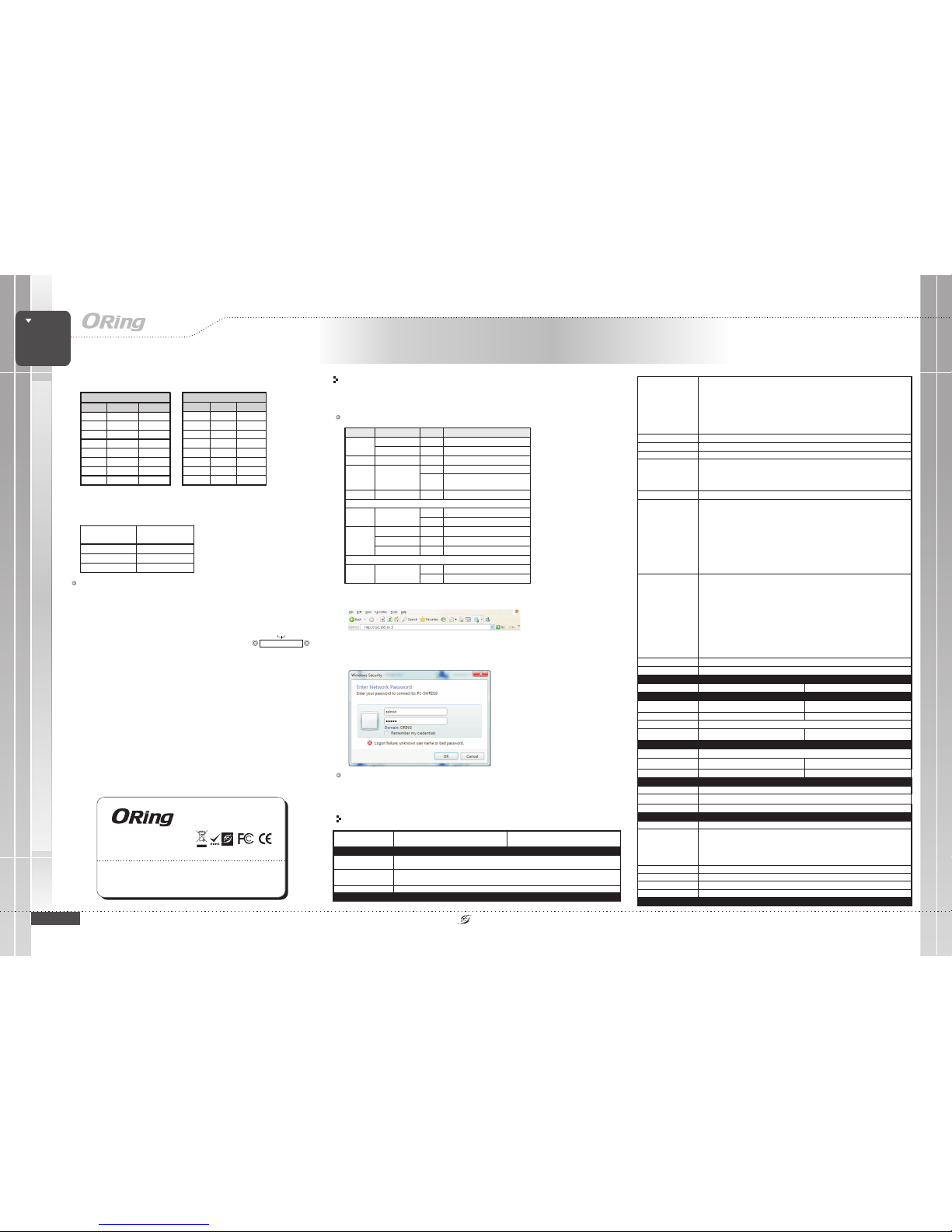
Configurations
After installingthe switch andconnecting cables, startthe switch byturning on power.
The greenpower LED shouldturn on.
LED indication table
1. Launchthe Internet Explorerand type inIP address ofthe switch.The default staticIP address is
192.168.10.1
2. Login with defaultuser name andpassword (both are ). After logging in,you should see
the following screen.For more information on configurations, please referto the usermanual. For
information onoperating the switchusing ORing’s Open-Visionmanagement utility,please go to
ORing website.
admin
LED Color Statu s Description
Green On System power on
PWR
Green Blinking Upgrad ing firmwar e
R.M Green On Ring Master
On Ring enabled
Ring Green
Blinking Ring st ructure is br oken
Fault Amber On Errors (For por t malfunctioni ng)
10/100/1000Base -T(X) RJ45 por t
On Port connected
Link/Act Green
Blinking Transmit ting data
Green On Port is runn ing at 1000Mbps
Amber O n Port is running at 100Mbps
Speed
Green / Amber Off Port is running at 10M bps
100/1000Base-X S FP port
On Port connected
Link/Act Green
Blinking Transmit ting data
RGS-92222GCP-NP-E
Faultcontact
Relay
None Relayoutput to carrycapacity of 1Aat 24VDC
100~240VACwith power socke,and dual 48VDC
(36~72VDC) power inputsat 6-pin terminalblock
23Watts
ReversePolarityProtectionon
DCinput(s)
-
Present
4360g
441(W)x342(D)x44(H)mm
(17x 13.46 x1.73 inches)
RGS-92222GCP-NP Series
RGS-92222GCP-NP Series
V+ V- V- V+
3A@24V
DCPower 48V
PW2 PW3
 Loading...