

ORiNG RGS-7244GP, RGS-7244GP-E, Thunder Rack RGS-7168GCP, Thunder Rack RGS-7168GCP-E, Thunder User Manual
...
RRGGSS--77224444GGPP // RRGGSS--77224444GGPP--EE
IInndduussttrriiaall MMaannaaggeedd GGiiggaabbiitt EEtthheerrnneett SSwwiittcchh
UUsseerr’’ss M
Maannuuaall
VVeerrssiioonn 11..33
DDeecceemmbbeerr,, 22001100
wwwwww..oorriinngg--nneettwwoorrkkiinngg..ccoomm

RGS-7244GP(-E) User’s Manual
ORing Industrial Networking Corp 1
COPYRIGHT NOTICE
Copyright © 2010 ORing Industrial Networking Corp.
All rights reserved.
No part of this publication may be reproduced in any form without the prior written consent of
ORing Industrial Networking Corp.
TRADEMARKS
is a registered trademark of ORing Industrial Networking Corp.
All other trademarks belong to their respective owners.
REGULATORY COMPLIANCE STATEMENT
Product(s) associated with this publication complies/comply with all applicable regulations.
Please refer to the Technical Specifications section for more details.
WARRANTY
ORing warrants that all ORing products are free from defects in material and workmanship for
a specified warranty period from the invoice date (5 years for most products). ORing will repair
or replace products found by ORing to be defective within this warranty period, with shipment
expenses apportioned by ORing and the distributor. This warranty does not cover product
modifications or repairs done by persons other than ORing-approved personnel, and this
warranty does not apply to ORing products that are misused, abused, improperly inst alled, or
damaged by accidents.
Please refer to the Technical Specifications section for the actual warranty period(s) of the
product(s) associated with this publication.
DISCLAIMER
Information in this publication is intended to be accurate. ORing shall not be responsible for its
use or infringements on third-parties as a result of its use. There may occasionally be
unintentional errors on this publication. ORing reserves the right to revise the contents of this
publication without notice.
CONTACT INFORMATION
ORing Industrial Networking Corp.
4F., No. 3, Lane 235, Baoqiao Rd., Xindian District, New Taipei City 23145, Taiwan (R.O.C.)
Tel: + 886 2 2918 3036 // Fax: + 886 2 2918 3084
Website: www.oring-networking.com
T echnical Support
E-mail: support@oring-networking.com
Sales Contact
E-mail: sales@oring-networking.com
(Headquarters)
sales@oring-networking.com.cn
(China)

RGS-7244GP(-E) User’s Manual
ORing Industrial Networking Corp 2
Table of Content
Getting to Know Your Switch........................................................................5
1.1 About the RGS-7244GP(-E) Industrial Switch................................................................5
1.2 Software Features..............................................................................................................6
1.3 Hardware Features.............................................................................................................6
Hardware Overview........................................................................................7
2.1 Front Panel..........................................................................................................................7
2.2 Rear Panel...........................................................................................................................9
2.3 Rack mount kit assembly...................................................................................................9
2.4 Front Panel LEDs .............................................................................................................10
Cables...........................................................................................................11
3.1 Ethernet Cables................................................................................................................11
3.1.1 100BASE-TX/10BASE-T Pin Assignments................................................................... 11
3.2 SFP.....................................................................................................................................13
3.3 Console Cable...................................................................................................................13
WEB Management........................................................................................14
4.1 Configuration by Web Browser.......................................................................................14
4.1.1 About W eb-based Management......................................................................................14
4.1.2 Basic Setting...................................................................................................................16
4.1.2.1 System Information......................................................................................... 16
4.1.2.2 Admin & Password ......................................................................................... 17
4.1.2.3 IP Setting........................................................................................................ 17
4.1.2.4 HTTPS............................................................................................................ 19
4.1.2.5 SSH ................................................................................................................ 19
4.1.2.6 LLDP............................................................................................................... 20
4.1.2.7 Backup/Restore Configuration ....................................................................... 23
4.1.2.8 Firmware Update............................................................................................ 23
4.1.3 DHCP Server..................................................................................................................24
4.1.3.1 Setting....................................................................................................... 24
4.1.3.2 DHCP Dynamic Client List........................................................................ 24
4.1.3.3 DHCP Client List ....................................................................................... 24
4.1.4 Port Setting.....................................................................................................................25

RGS-7244GP(-E) User’s Manual
ORing Industrial Networking Corp 3
4.1.4.1 Port Control............................................................................................... 25
4.1.4.2 Rate Limit.................................................................................................. 26
4.1.4.3 Port Trunk.................................................................................................. 27
4.1.4.4 Loop Guard ............................................................................................... 32
Loop Guard is a looping detection/avoid strategy, it helps network administrator to
avoid looping issue.....................................................................................................32
4.1.5 Redundancy....................................................................................................................32
4.1.5.1 O-Ring....................................................................................................... 32
4.1.5.2 MSTP ........................................................................................................ 33
4.1.6 VLAN.............................................................................................................................43
4.1.6.1 VLAN Membership Configuration.............................................................. 43
4.1.6.2 Private VLAN............................................................................................. 51
4.1.7 SNMP.............................................................................................................................53
4.1.7.1 SNMP-System........................................................................................... 53
4.1.7.2 SNMP-Communities.................................................................................. 55
4.1.7.3 SNMP-Users ............................................................................................. 56
4.1.7.4 SNMP-Groups........................................................................................... 57
4.1.7.5 SNMP-Views............................................................................................. 58
4.1.7.6 SNMP-Accesses ....................................................................................... 59
4.1.8 Traffic Prioritization.......................................................................................................60
4.1.8.1 Port Configuration ..................................................................................... 60
4.1.8.2 QoS Control List........................................................................................ 62
4.1.8.3 Storm Control............................................................................................63
4.1.8.4 Wizard....................................................................................................... 64
4.1.9 IGMP Snooping..............................................................................................................65
4.1.9.1 IGMP Snooping......................................................................................... 65
4.1.9.2 IGMP Snooping S tatus.............................................................................. 66
4.1.10 Security ......................................................................................................................67
4.1.10.1 ACL ........................................................................................................... 67
4.1.10.2 802.1x........................................................................................................ 68
4.1.11 Warning (only for RGS-7244GC-E model)...............................................................71
4.1.11.1 Fault Alarm................................................................................................ 71
4.1.11.2 System Warning........................................................................................ 71
4.1.12 Monitor and Diag.......................................................................................................72
4.1.12.1 MAC Table................................................................................................. 72
4.1.12.2 Mirroring.................................................................................................... 74
4.1.12.3 System Log Information............................................................................ 75

RGS-7244GP(-E) User’s Manual
ORing Industrial Networking Corp 4
4.1.12.4 Detailed Log.............................................................................................. 76
4.1.12.5 Traffic Overview.........................................................................................77
4.1.12.6 Detailed Statistics......................................................................................78
4.1.12.7 Ping........................................................................................................... 79
4.1.12.8 VeriPHY..................................................................................................... 80
4.1.13 System Reboot ...........................................................................................................81
4.1.14 Factory Defaults.........................................................................................................82
Command Line Interface Management ......................................................83
5.1 About CLI Management........................................................................................................83
Technical Specifications .............................................................................95

RGS-7244GP(-E) User’s Manual
ORing Industrial Networking Corp 5
Getting to Know Your Switch
1.1 About the RGS-7244GP(-E) Industrial Switch
RGS-7244GP series are the managed redundant ring Ethernet switches with
24x10/100/1000Base-(TX) ports and 4x1000Base-X SFP ports. With complete support of
Ethernet Redundancy protocol, O-Ring (Gigabit model recovery time < 20ms over 250 units of
connection) and MSTP/RSTP/STP (IEEE 802.1s/w/D) can protect your mission-critical
applications from network interruptions or temporary malfunctions with its fast recovery
technology.
ORing’s Thunder Series Ethernet switches provide advanced IP-based bandwidth
management which can limit the maximum bandwidth for each IP device. User can configure
IP camera and NVR with more bandwidth and limit other device bandwidth.
ORing’s Thunder Series Ethernet switches also support application-based QoS.
Application-based QoS can set highest priority for data stream according to TCP/UDP port
number. ORing’s special IP police function can permit only allowed IP address with MAC
address to access the networking. Hacker cannot access the IP surveillance network without
permission. It can avoid hacker from stealing video privacy data and attacking IP camera,
NVR and controllers.
Moreover, ORing’s Thunder Series Ethernet switches provide advanced DoS/DDoS auto
prevention. If there is any IP flow become big in short time, ORing’s thunder switch will lock
the source IP address for certain time to prevent the attack. It is hardware-based prevention
so it can prevent DDOS attack immediately and completely. And all functions of
RGS-7244GP can also be managed centralized and convenient by Open-Vision v3.0, except
the Web-based interface, Telnet and console (CLI) configuration. Therefore, the switch is one
of the most reliable choice for highly-managed and Gigabit Fiber Ethernet application.

RGS-7244GP(-E) User’s Manual
ORing Industrial Networking Corp 6
1.2 Software Features
Industry’s fastest Redundant Ethernet Ring (Gigabit model recovery time < 20ms over
250 units connection)
Suppo rt Ring Coupling, Dual Homing over Ring and standard STP/RSTP
Suppo rt SNMPv1/v2c/v3 & RMON & Port base/802.1Q VLAN Network Management
Event notification by Email and SNMP trap
Wind ows Utility, Web-based ,Telnet and Console(CLI) configuration
Enable/disable ports, MAC based port security
Port based n etwork access control (802.1x)
VLAN (80 2.1q ) to segregate and secure network traffic
RADIUS centralized password management
SNMPv3 encrypted authe ntication and access security
Quality of Service (80 2.1p) for real-time traffic
VLAN (80 2.1q) with double tagging and GVRP supported
IGMP Snoopi ng for multicast filtering
Port config uration, status, statistics, mirroring, security
Remote Monitoring (RMON)
1.3 Hardware Features
One 10 0~240VAC power input and RGS-7244GP-E added dual 36~72VDC power
inputs.
Operating Te mperature : -40 to 70
o
C
Storage Temperature : -40 to 85
o
C
Operating Hu midity : 5% to 95%, non-conden sing
Casing: IP-20
Provided 2 4 x 10/100/1000Base –T(X) RJ-45 ports
Provided 4 x 1000 Ba se-X SFP ports
Con sole Port (DB9 Female connector)
Dimensions :
RGS-7244GP : 443.7 (W) x 200 (D) x 44 (H) mm
RGS-7244GP-E : 431 (W) x 342 (D) x 44 (H) mm
RGS-7244GP(-E) User’s Manual
ORing Industrial Networking Corp 7
Hardware Overview
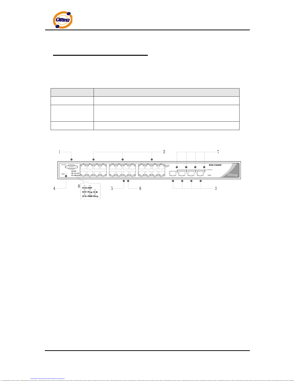
2.1 Front Panel
The following table describes the labels that stick on the RGS-7244GP(-E)
Port Description
Gigabit SFP ports
4 x 1000Base-X on SFP port
Gigabit Ethernet
Port
24 x 10/100/1000Base–T(X)
Console
Use RS-232 with DB9 connecter to manage switch.
RGS-7244GP
1. Console port (DB9 Female connector)
2. 10/100/1000Base-T(X) gigabits Ethernet port
3. 1000Base-X Fiber port on SFP port
4. Reset button. Push the button 3 seconds for reset; 5 seconds for factory default.
5. LED for Ethernet ports Link/Act status : Left Green for 1000Mbps indicator, Amber for
10/100Mbps indicator
6. LED for Ethernet ports Duplex status.
7. LED for SFP ports Link/Act status.
8. Front panel LED Status:
.LED for ST A. Green : Indicate that the system is ready . The LED is blinking when the
system is upgrading firmware
.LED for PWR. The LED lights on when the power module is activated.
.LED for R.M (Ring master). When the LED light on, it means that the switch is the ring
master of Ring.
.LED for Ring. When the led light on, it means the O-Ring is activated.
.LED for DEF: System resets to default configuration.

RGS-7244GP(-E) User’s Manual
ORing Industrial Networking Corp 8
.LED for Ping: System is processing “PING” request.
.LED for RUN: System is operating continuously.
.LED for RMT: System is accessed remotely.
RGS-7244GP-E
1. Console port (DB9 Female connector)
2. 10/100/1000Base-T(X) gigabits Ethernet port
3. 1000Base-X Fiber port on SFP port
4. Reset button: Push the button 3 seconds for reset; 5 seconds for factory default.
5. LED for Ethernet ports Link/Act status : Left Green for 1000Mbps indicator, Amber for
10/100Mbps indicator
6. LED for Ethernet ports Duplex status.
7. LED for SFP ports Link/Act status
8. Front Panel LED St atus:
.LED for PW1: When the PWR1 links, the green led will be light on.
.LED for PW2: When the PWR2 links, the green led will be light on.
.LED for PW3: When the PWR3 links, the green led will be light on.
.LED for STA: Green : Indicates that the system ready. The LED is blinking when the
system is upgrading firmware
.LED for PWR: This LED lights on when the power module is activated.
.LED for R.M. (Ring master): When the LED lights on, this switch is designated as the
ring master of the Ring topology.
.LED for Ring: When the led light on, the O-Ring is activated.
.LED for DEF: System resets to default configuration.
.LED for Ping: System is processing “PING” request.
.LED for RUN: System is operating continuously.
.LED for RMT: System is accessed remotely.
.LED for Fault: Indicates unexpected event occurred.
RGS-7244GP(-E) User’s Manual
ORing Industrial Networking Corp 9
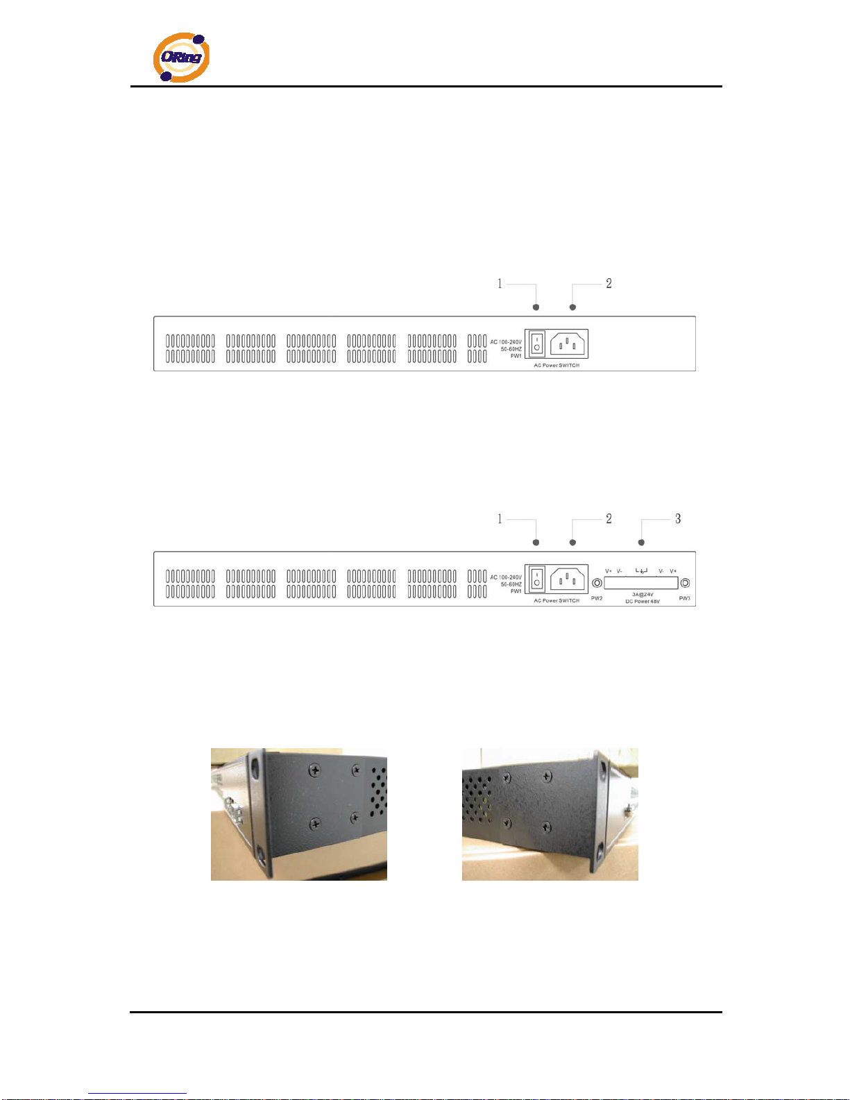
2.2 Rear Panel
The rear panel of RGS-7244GP is sho wn as below:
1. Power Switch
2. Power input for AC 100V~240V / 50~60Hz
The rear panel of RGS-7244GP-E is shown as below:
1. Power Switch
2. Power input for AC 100V~240V / 50~60Hz
3. Dual power inputs for DC
2.3 Rack mount kit assembly
You can find the rack mount kit and the screws in the packing box. Please assembly the rack
mount kit on the switch with screws as shown below:
RGS-7244GP(-E) User’s Manual
ORing Industrial Networking Corp 10
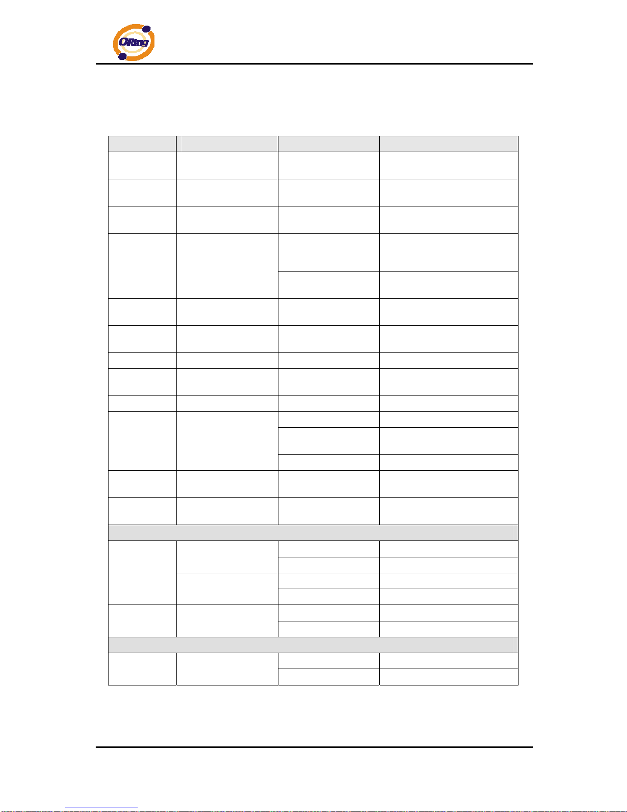
2.4 Front Panel LEDs
LED Color Status Description
PW1
Green On
When the PWR1 links, the
green led will be light on.
PW2
Green On
When the PWR2 links, the
green led will be light on.
PW3
Green On
When the PWR3 links, the
green led will be light on.
On
When the power module is in
PWR UP state, the green LED
lights on.
STA
Green
Blinking
When the system is
upgrading firmware
DEF
Green On
System resets to default
configuration.
RUN
Green Slowly blinking
System is operating
continuously.
PWR
Green On DC power module activated.
Ping
Green Blinking
When the led light on, System
is processing “PING” request
RMT
Green Blinking System is accessed remotely.
On Ring enabled.
Slowly blinking
Ring has only One link. (lacks
one link to build the ring)
Ring
Green
Fast blinking Ring work normally.
R.M
Green On
When the system is operating
in O-Ring Master mode
Fault
Amber On
Indicates unexpected event
occurred.
10/100/1000Base-T(X) Gigabit Ethernet port s
On Port speed 1000M link up
Left Green (two color
LED)
Blinking Data Transmitted on 1000M
On Port speed 10/100M link up
LINK/ACT
Left Amber (two color
LED)
Blinking Data Transmitted on 10/100M
On Full-Duplex
Full-Duplex
Right Amber
Blinking Half-Duplex
SFP
On Port link up.
LINK/ACT
Green
Blinking Data transmitted
RGS-7244GP(-E) User’s Manual
ORing Industrial Networking Corp 11
Cables
3.1 Ethernet Cables
The RGS-7244GP(-E) switches has standard Ethernet ports. According to the link type,
the switch use CAT 3, 4, 5,5e UTP cables to connect to any other network device (PCs,
servers, switches, routers, or hubs). Please refer to the following table for cable
specifications.
Cable Types and Specifications
Cable Type Max. Length Connector
10BASE-T Cat. 3, 4, 5 100-ohm UTP 100 m (328 ft) RJ-45
100BASE-TX Cat. 5 100-ohm UTP UTP 100 m (328 ft) RJ-45
1000BASE-T
Cat. 5/Cat. 5e 100-ohm
UTP
UTP 100 m (328ft) RJ-45
3.1.1 100BASE-TX/10BASE-T Pin Assignments
With 100BASE-TX/10BASE-T cable, pins 1 and 2 are used for transmitting data, and
pins 3 and 6 are used for receiving data.
10/100 Base-T(X) RJ-45 Pin Assignments
Pin Number Assignment
1 TD+
2 TD3 RD+
4 Not used
5 Not used
6 RD7 Not used
8 Not used
RGS-7244GP(-E) User’s Manual
ORing Industrial Networking Corp 12
1000 Base-T RJ-45 Pin Assignments
Pin Number Assignment
1 BI_DA+
2 BI_DA3 BI_DB+
4 BI_DC+
5 BI_DC6 BI_DB7 BI_DD+
8 BI_DD-
The RGS-7244GP(-E) switches support auto MDI/MDI-X operation. You can use a
straight-through cable to connect PC to switch. The following table below shows the
10BASE-T/ 100BASE-TX MDI and MDI-X port pin outs.
10/100 Base-T MDI/MDI-X pins assignment
Pin Number MDI port MDI-X port
1 TD+(transmit) RD+(receive)
2 TD-(transmit) RD-(receive)
3 RD+(receive) TD+(transmit)
4 Not used Not used
5 Not used Not used
6 RD-(receive) TD-(transmit)
7 Not used Not used
8 Not used Not used
1000 Base-T MDI/MDI-X pins assignment
Pin Number MDI port MDI-X port
1 BI_DA+ BI_DB+
2 BI_DA- BI_DB3 BI_DB+ BI_DA+
4 BI_DC+ BI_DD+
5 BI_DC- BI_DD6 BI_DB- BI_DA7 BI_DD+ BI_DC+
8 BI_DD- BI_DC-
Note: “+” and “-” signs represent the polarity of the wires that make up each wire pair.

RGS-7244GP(-E) User’s Manual
ORing Industrial Networking Corp 13
3.2 SFP
The Switch has fiber optical ports with SFP connectors. The fiber optical port s are in
multi-mode (0 to 550M, 850 nm with 50/125 µm, 62.5/125 µm fiber) and single-mode with LC
connector. Please remember that the TX port of Switch A should be connected to the RX port
of Switch B.
Switch A Switch B
3.3 Console Cable
RGS-7244GP(-E) switches can be management by console port. The DB-9 to RJ-45 cable
can be found in the package. You can connect them to PC via a RS-232 cable with DB-9
female connector and the other end (RJ-45 connector) connects to consol e port of switch.
PC pin out (male) assignment RS-232 with DB9 female connector DB9 to RJ 45
Pin #2 RD Pin #2 TD Pin #2
Pin #3 TD Pin #3 RD Pin #3
Pin #5 GD Pin #5 GD Pin #5
Fiber cord

RGS-7244GP(-E) User’s Manual
ORing Industrial Networking Corp 14
WEB Management
4.1 Configuration by Web Browser
This section introduces the configuration by Web browser.
4.1.1 About Web-based Management
An embedded HTML web site resides in flash memory on the CPU board. It contains
advanced management features and allows you to manage the switch from anywhere on the
network through a standard web browser such as Microsoft Internet Explorer.
The Web-Based Management function supports Internet Explorer 5.0 or later. It is based
on Java Applets with an aim to reduce network bandwidth consumption, enhance access
speed and present an easy viewing screen.
Note: By default, IE5.0 or late r version does not allow Java Applets to open sockets. You need to explicitly modify
the browser setting in order to enable Java Applets to use network ports.
Preparing for Web Management
The default value is as below:
IP Address: 192.168.10.1
Subnet Mask: 255.255.255.0
Default Gateway: 192.168.10.254
User Name: admin
Password: admin
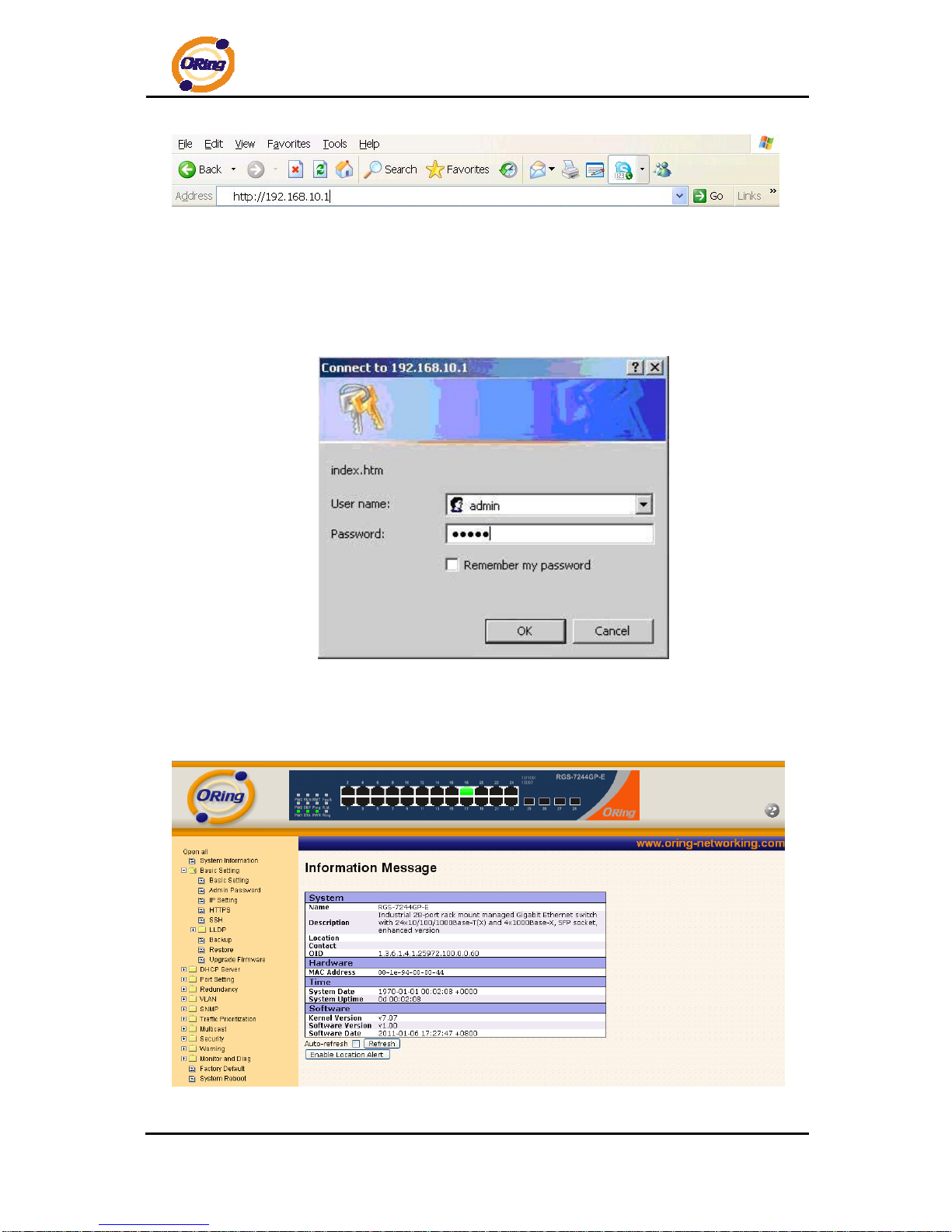
System Login
1. Launch the Internet Explorer.
2. Type http:// and the IP address of the switch. Press “Enter”.
RGS-7244GP(-E) User’s Manual
ORing Industrial Networking Corp 15
3. The login screen appears.
4. Key in the username and password. The default username and password is
“admin”.
5. Click “Enter” or ”OK” button, then the main interface of the Web-based
management appears.
Login screen
Main Interface
Main interface
RGS-7244GP(-E) User’s Manual
ORing Industrial Networking Corp 16
4.1.2 Basic Setting
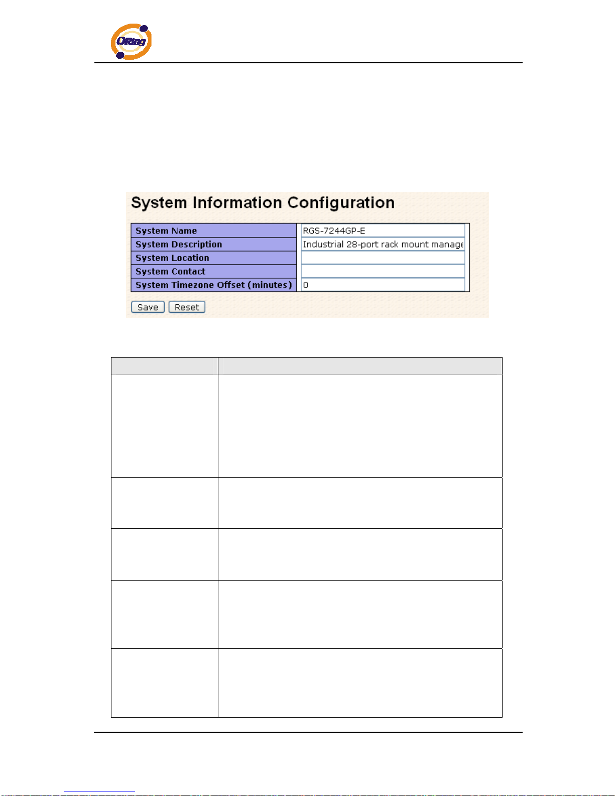
4.1.2.1 System Information
The switch system information is provided here.
System Information interface
.
Label Description
System Name
An administratively assigned name for this managed node. By
convention, this is the node's fully-qualified domain name – a text
string (0 to 255 characters) drawn from the alphabet (A-Z, a-z),
digits (0-9), and the minus sign (-). No space characters are
permitted as part of a name. The first character must be an
alphabet, and the first or last character must not be a minus sign.
System
Description
The administratively assigned description for this managed
node. The allowed string length is 0 to 255, and the allowed
contents are the ASCII characters from 32 to 126.
System Location
The physical location of this node (e.g., telephone closet, 3rd
floor). The allowed string length is 0 to 255, and the allowed
content is the ASCII characters from 32 to 126.
System Contact
The textual identification of the contact person for this managed
node, together with information on how to contact this person.
The allowed string length is 0 to 255, and the allowed content is
the ASCII characters from 32 to 126.
Timezone Offset
Enter the name of contact person or organization
Provide the time zone offset relative to UTC/GMT.
The offset is given in minutes east of GMT. The valid range is from
-720 to 720 minutes.
RGS-7244GP(-E) User’s Manual
ORing Industrial Networking Corp 17
Click to save changes.
Click to undo any changes made locally and revert to previously
saved values.
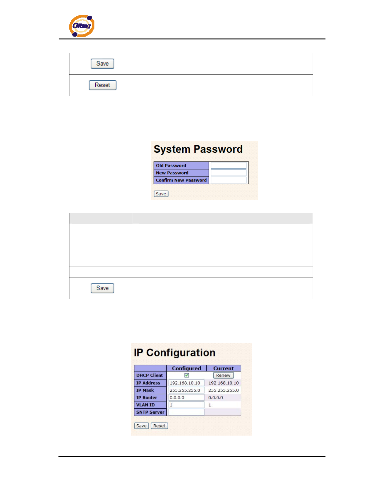
4.1.2.2 Admin & Password
This page allows you to configure the system password required to access the web p ages or
log in from CLI.
Label Description
Old Password
Enter the current system password. If this is incorrect, the new
password will not be set.
New Password
The system password. The allowed string length is 0 to 31, and
the allowed content is the ASCII characters from 32 to 126.
Confirm password
Re-type the new password.
Click to save changes.
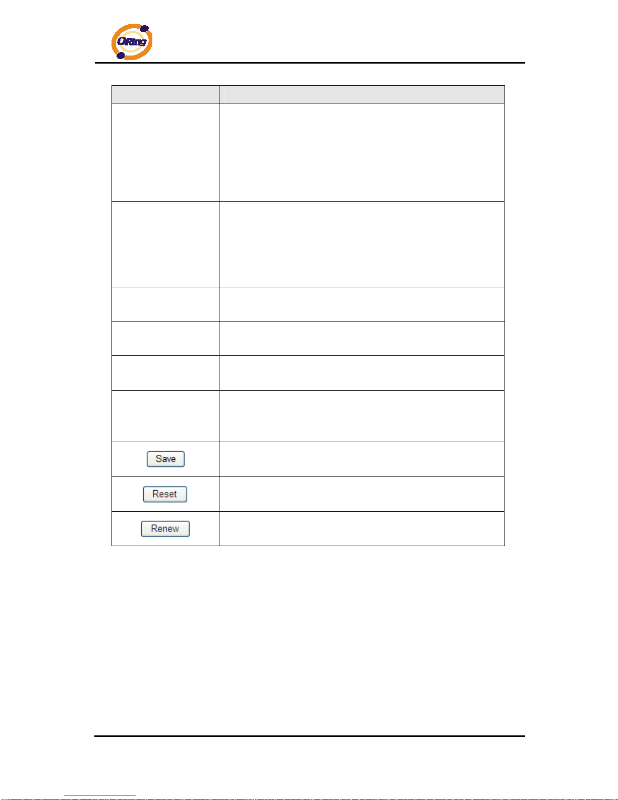
4.1.2.3 IP Setting
Configure the switch-managed IP information on this pag e.
RGS-7244GP(-E) User’s Manual
ORing Industrial Networking Corp 18
Label Description
DHCP Client
Enable the DHCP client by checking this box. If DHCP fails and
the configured IP address is zero, DHCP will retry. If DHCP fails
and the configured IP address is non-zero, DHCP will stop and
the configured IP settings will be used. The DHCP client will
announce the configured System Name as hostname to provide
DNS lookup.
IP Address
Assign the IP address that the network is using. If DHCP client
function is enabling, you do not need to assign the IP address.
The network DHCP server will assign the IP address for the
switch and it will be display in this column. The default IP is
192.168.10.1
IP Mask
Assign the subnet mask of the IP address. If DHCP client function
is enabling, you do not need to assign the subnet mask
IP Router
Assign the network gateway for the switch. The default gateway
is 192.168.10.254
VLAN ID
Provide the managed VLAN ID. The allowed range is 1 through
4095.
SNTP Server
SNTP is an acronym for Simple Network T ime Protocol, a netwo rk
protocol for synchronizing the clocks of computer systems. SNTP
uses UDP (datagrams) as transport layer.
Click to save changes.
Click to undo any changes made locally and revert to previously
saved values.
Click to renew DHCP. This button is only available if DHCP is
enabled.
RGS-7244GP(-E) User’s Manual
ORing Industrial Networking Corp 19
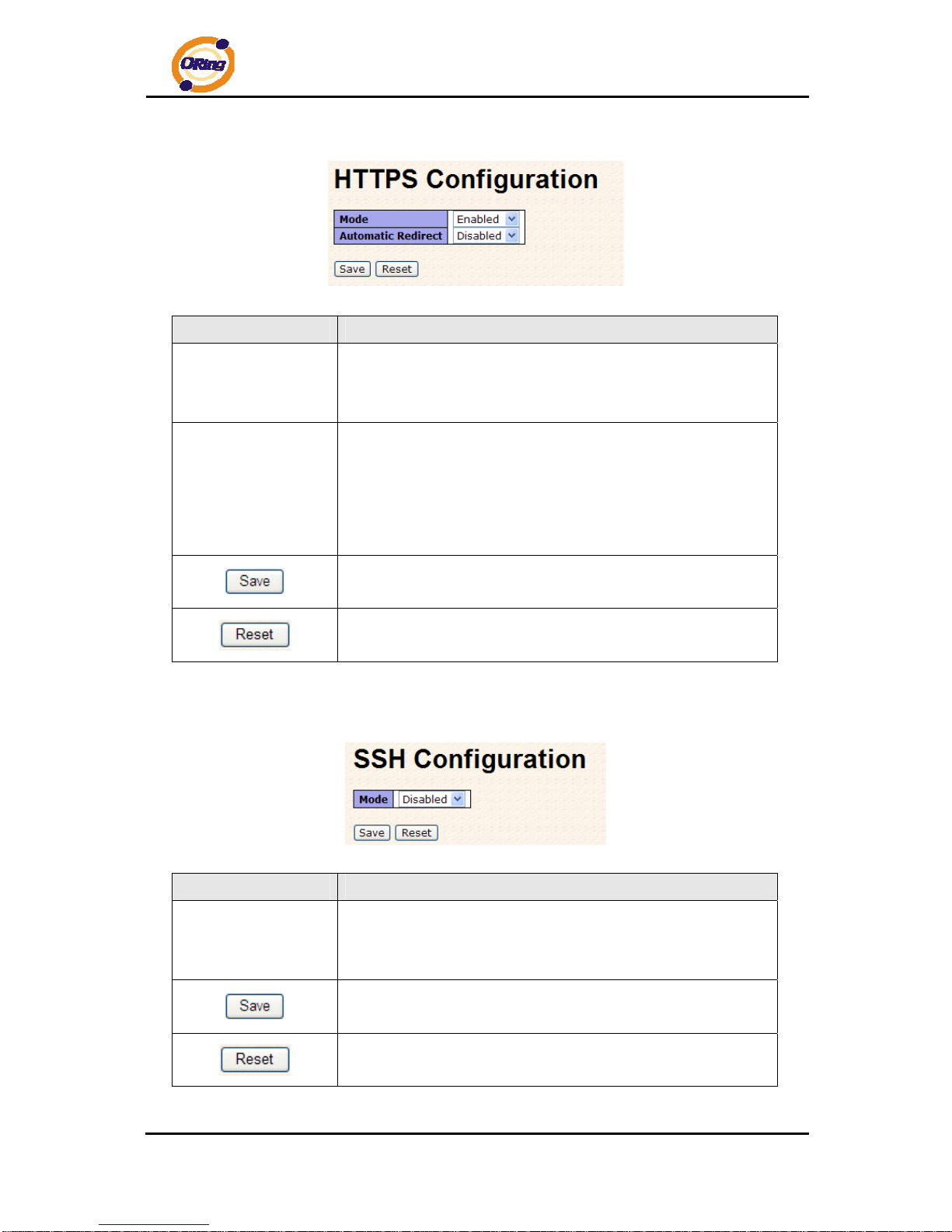
4.1.2.4 HTTPS
Label Description
Mode
Indicates the HTTPS mode operation. Possible modes are:
Enabled: Enable HTTPS mode operation.
Disabled: Disable HTTPS mode operation.
Automatic Redirect
Indicates the HTTPS redirect mode operation. Automatic redirect
web browser to HTTPS during HTTPS mode enabled. Possible
modes are:
Enabled: Enable HTTPS redirect mode operation.
Disabled: Disable HTTPS redirect mode operation.
Click to save changes.
Click to undo any changes made locally and revert to previously
saved values.
4.1.2.5 SSH
Label Description
Mode
Indicates the SSH mode operation. Possible modes are:
Enabled: Enable SSH mode operation.
Disabled: Disable SSH mode operation.
Click to save changes.
Click to undo any changes made locally and revert to previously
saved values.
RGS-7244GP(-E) User’s Manual
ORing Industrial Networking Corp 20
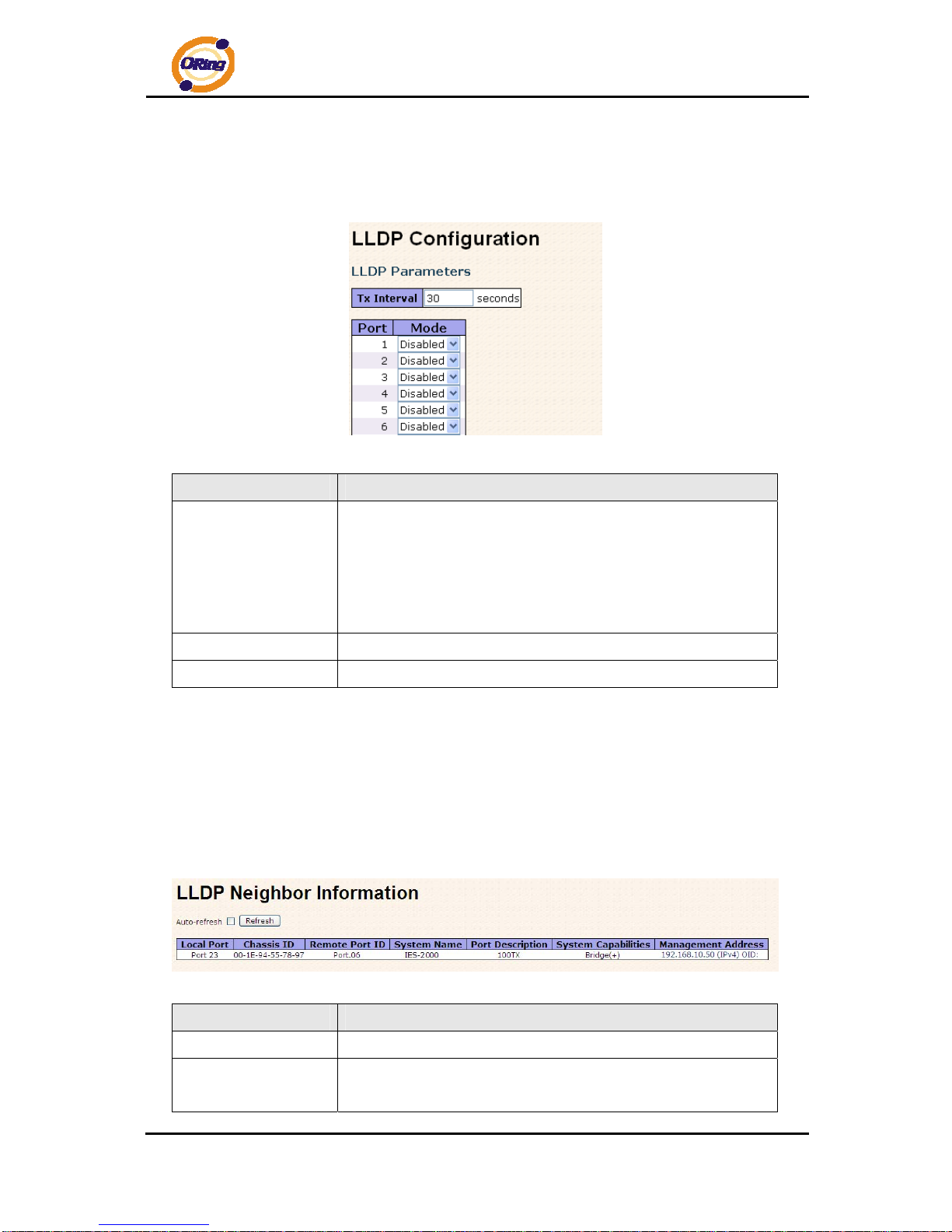
4.1.2.6 LLDP
LLDP Parameters
This page allows the user to inspect and configure the current LLDP port settings.
Label Description
Tx Interval
The switch is periodically transmitting LLDP frames to its
neighbors for having the network discovery information
up-to-date. The interval between each LLDP frame is determined
by the Tx Interval value. Valid values are restricted to 5 - 32768
seconds.
Port
The switch port number of the logical LLDP port.
Mode
Enable or disable LLDP
LLDP Neighbor Information
This page provides a status overview for all LLDP neighbors. The displayed table contains a
row for each port on which an LLDP neighbor is detected. The columns hold the following
information:
Label Description
Local Port
The port on which the LLDP frame was received.
Chassis ID
The Chassis ID is the identification of the neighbor's LLDP
frames.
RGS-7244GP(-E) User’s Manual
ORing Industrial Networking Corp 21
Remote Port ID
The Remote Port ID is the identification of the neighbor port.
System Name
System Name is the name advertised by the neighbor unit.
Port Description
Port Description is the port description advertised by the neighbor
unit.
System Capabilites
System Capabilities describes the neighbor unit's capabilities.
The possible capabilities are:
1. Other
2. Repeater
3. Bridge
4. WLAN Access Point
5. Router
6. Telephone
7. DOCSIS cable device
8. Station only
9. Reserved
When a capability is enabled, the capability is followed by (+). If
the capability is disabled, the capability is followed by (-).
Management
Address
Management Address is the neighbor unit's address that is used
for higher layer entities to assist the discovery by the network
management. This could for instance hold the neighbor's IP
address.
Click to refresh the page immediately.
Check this box to enable an automatic refresh of the page at
regular intervals.
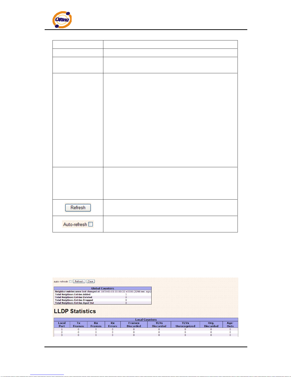
LLDP Statistics
This page provides an overview of all LLDP traffic.
Two types of counters are shown. Global counters are counters that refer to the whole stack,
switch, while local counters refer to counters for the currently selected switch.

RGS-7244GP(-E) User’s Manual
ORing Industrial Networking Corp 22
Global Counters
Label Description
Neighbor entries
were last changed at
Shows the time for when the last entry was last deleted or added.
It is also shows the time elapsed since last change was detected.
T otal Neighbors
Entries Added
Shows the number of new entries added since switch reboot.
T otal Neighbors
Entries Deleted
Shows the number of new entries deleted since switch reboot.
T otal Neighbors
Entries Dropped
Shows the number of LLDP frames dropped due to that the entry
table was full.
T otal Neighbors
Entries Aged Out
Shows the number of entries deleted due to Time-To-Live
expiring.
Local Counters
Label Description
Local Port
The port on which LLDP frames are received or transm itted.
Tx Frames
The number of LLDP frames transmitted on the port.
Rx Frames
The number of LLDP frames received on the port.
Rx Errors
The number of received LLDP frames containing some kind of
error.
Frames Discarded
If an LLDP frame is received on a port, and the switch's internal
table has run full, the LLDP frame is counted and discarded. This
situation is known as "Too Many Neighbors" in the LLDP
standard. LLDP frames require a new entry in the table when the
Chassis ID or Remote Port ID is not already contained within the
table. Entries are removed from the table when a given port links
down, an LLDP shutdown frame is received, or when the entry
ages out.
TL Vs Discarded
Each LLDP frame can contain multiple pieces of information,
known as TLVs (TLV is short for "Type Length Value"). If a TLV is
malformed, it is counted and discarded.
TL Vs Unrecognized
The number of well-formed TLVs, but with an unknown type
value.
Org. Discarded
The number of organizationally TLVs received.
RGS-7244GP(-E) User’s Manual
ORing Industrial Networking Corp 23
Age-Outs
Each LLDP frame contains information about how long time the
LLDP information is valid (age-out time). If no new LLDP frame is
received within the age out time, the LLDP information is
removed, and the Age-Out counter is incremented.
Click to refresh the page immediately.
Clears the local counters. All counters (including global counters)
are cleared upon reboot.
Check this box to enable an automatic refresh of the page at
regular intervals.
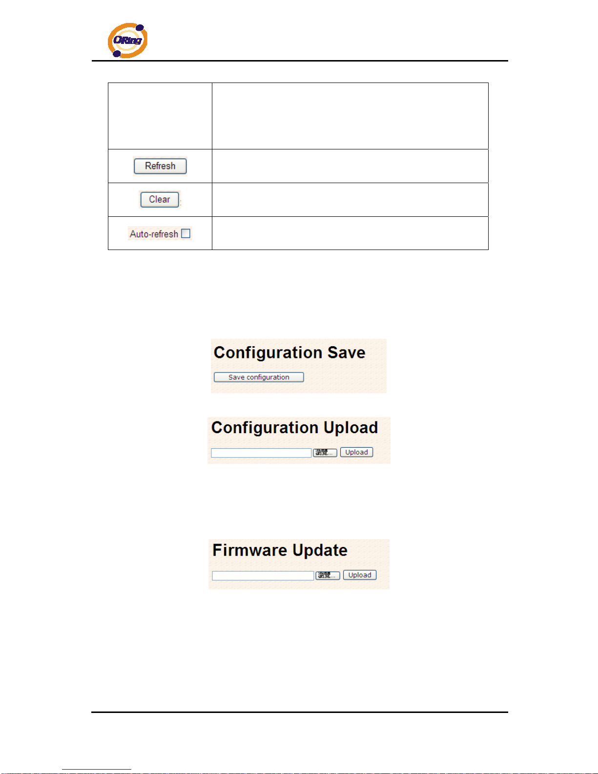
4.1.2.7 Backup/Restore Configuration
You can save/view or load the switch configuration. The configuration file is in XML format with
a hierarchy of tags:
4.1.2.8 Firmware Update
This page facilitates an update of the firmware controlling the stack. switch.
RGS-7244GP(-E) User’s Manual
ORing Industrial Networking Corp 24
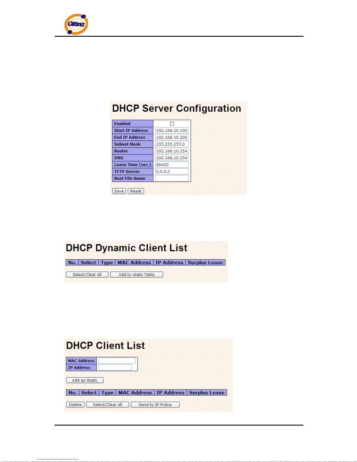
4.1.3 DHCP Server
4.1.3.1 Setting
The system provides with DHCP server function. Enable the DHCP server function, the
switch system will be a DHCP server.
4.1.3.2 DHCP Dynamic Client List
When the DHCP server function is activated, the system will collect the DHCP client
information and display in here.
4.1.3.3 DHCP Client List
You can assign the specific IP address which is in the assigned dynamic IP range to the
specific port. When the device is connecting to the port and asks for dynamic IP assigning,
the system will assign the IP address that has been assigned before in the connected device.
RGS-7244GP(-E) User’s Manual
ORing Industrial Networking Corp 25
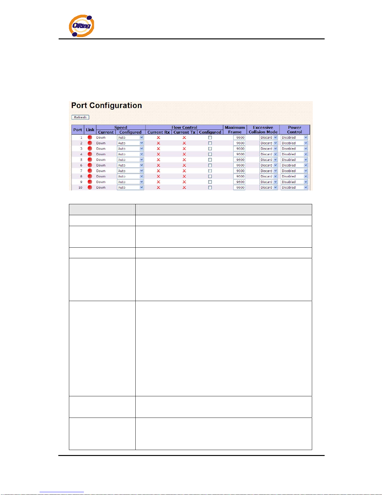
4.1.4 Port Setting
4.1.4.1 Port Control
This page displays current port configurations. Ports can also be configure d here.
Label Description
Port
This is the logical port number for this row.
Link
The current link state is displayed graphically. Green indicates the
link is up and red that it is down.
Current Link Speed
Provides the current link speed of the port.
Configured Link
Speed
Select any available link speed for the given switch port.
Auto Speed selects the highest speed that is compatible with a
link partner.
Disabled disables the switch port operation.
Flow Control
When Auto Speed is selected for a port, this section indicates the
flow control capability that is advertised to the link partner.
When a fixed-speed setting is selected, that is what is used. The
Current Rx column indicates whether pause frames on the port
are obeyed, and the Current Tx column indicates whether pause
frames on the port are transmitted. The Rx and Tx settings are
determined by the result of the last Auto-Negotiation.
Check the configured column to use flow control. This setting is
related to the setting for Configured Link Speed.
Maximum Frame
Enter the maximum frame size allowed for the switch port,
including FCS. The allowed range is 1518 bytes to 9600 bytes.
Excessive Collision
Mode
Configure port transmit collision behavior.
Discard: Discard frame after 16 collisions (default).
Restart: Restart back-off algorithm after 16 collisions.
RGS-7244GP(-E) User’s Manual
ORing Industrial Networking Corp 26
Power Control
The Usage column shows the current percentage of the power
consumption per port. The Configured column allows for changing
the power savings mode parameters per port.
Disabled: All power savings mechanisms disabled.
ActiPHY: Link down power savings enabled.
PerfectReach: Link up power savings enabled.
Enabled: Both link up and link down power savings enabled.
T otal Power Usage
Total power usage in board, measured in percent.
Click to save changes.
Click to undo any changes made locally and revert to previously
saved values.
Click to refresh the page. Any changes made locally will be
undone.
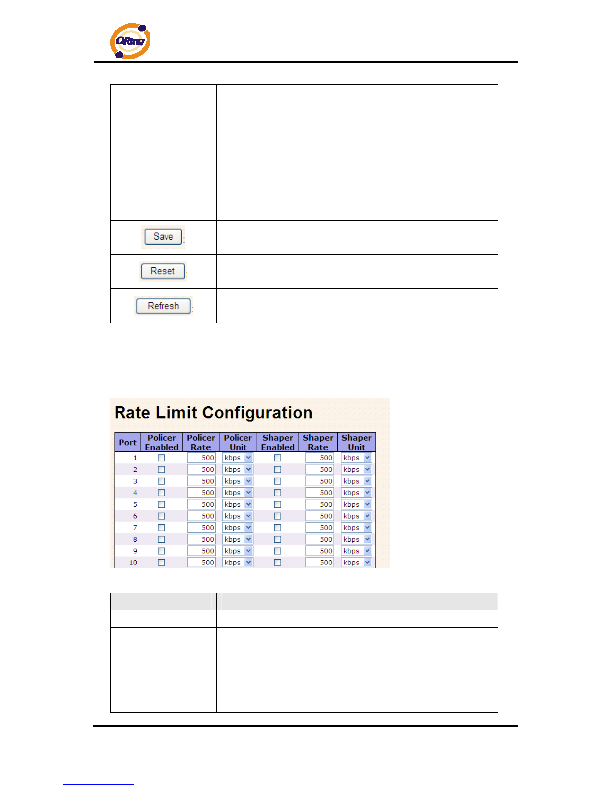
4.1.4.2 Rate Limit
Configure the switch port rate limit for Policers and Shapers on this page.
Label Description
Port
The logical port for the settings contained in the same row.
Policer Enabled
Enable or disable the port policer. The default value is "Disabled".
Policer Rate
Configure the rate for the port policer. The default value is "500".
This value is restricted to 500-1000000 when the "Policer Unit" is
"kbps", and it is restricted to 1-1000 when the "Policer Unit" is
"Mbps"
RGS-7244GP(-E) User’s Manual
ORing Industrial Networking Corp 27
Policer Unit
Configure the unit of measure for the port policer rate as kbps or
Mbps. The default value is "kbps".
Shaper Enabled
Enable or disable the port shaper. The default value is "Disabled".
Shaper Rate
Configure the rate for the port shaper. The default value is "500".
This value is restricted to 500-1000000 when the "Policer Unit" is
"kbps", and it is restricted to 1-1000 when the "Policer Unit" is
"Mbps"
Shaper Unit
Configure the unit of measure for the port shaper rate as kbps or
Mbps. The default value is "kbps".
Click to save changes.
Click to undo any changes made locally and revert to previously
saved values.
4.1.4.3 Port Trunk
4.1.4.3.1 Trunk Configuration
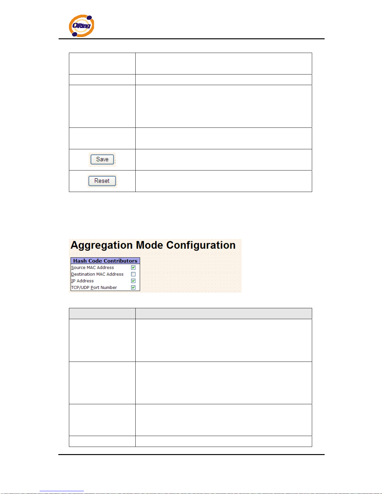
This page is used to configure the Aggregation hash mode and the aggregation group.
Label Description
Source MAC Address
The Source MAC address can be used to calculate the
destination port for the frame. Check to enable the use of the
Source MAC address, or uncheck to disable. By default, Source
MAC Address is enabled.
Destination MAC
Address
The Destination MAC Address can be used to calculate the
destination port for the frame. Check to enable the use of the
Destination MAC Address, or uncheck to disable. By default,
Destination MAC Address is disabled.
IP Address
The IP address can be used to calculate the destination port for
the frame. Check to enable the use of the IP Address, or uncheck
to disable. By default, IP Address is enabled.
TCP/UDP Port
The TCP/UDP port number can be used to calculate the
RGS-7244GP(-E) User’s Manual
ORing Industrial Networking Corp 28
Number
destination port for the frame. Check to enable the use of the
TCP/UDP Port Number, or uncheck to disable. By default,
TCP/UDP Port Number is enabled.
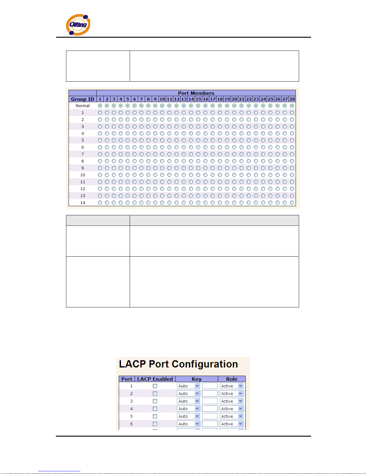
Label Description
Group ID
Indicates the group ID for the settings contained in the same row.
Group ID "Normal" indicates there is no aggregation. Only one
group ID is valid per port.
Port Members
Each switch port is listed for each group ID. Select a radio button
to include a port in an aggregation, or clear the radio button to
remove the port from the aggregation. By default, no ports belong
to any aggregation group. Only full duplex ports can join an
aggregation and ports must be in the same speed in each group.
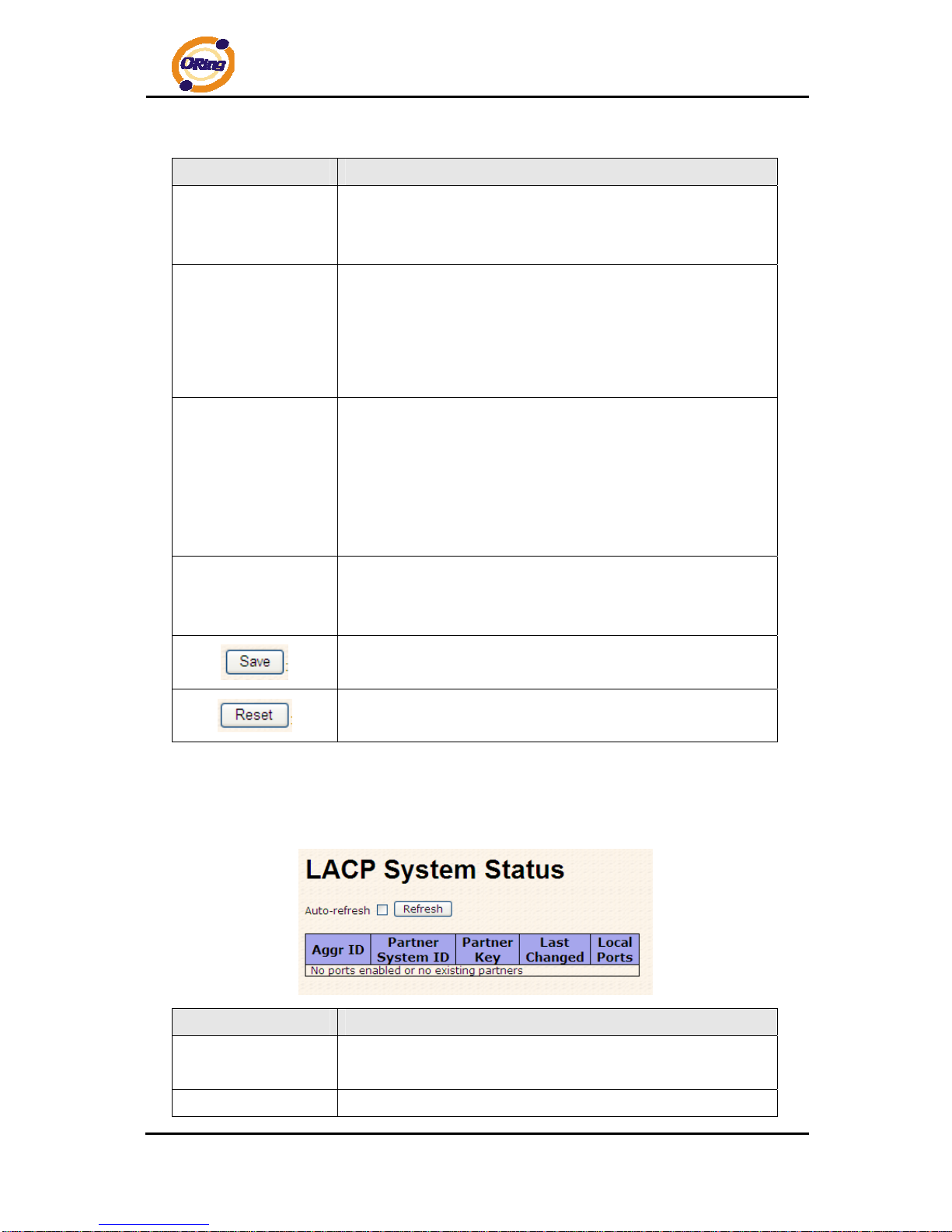
4.1.4.3.2 LACP Port Configuration
This page allows the user to inspect the current LACP port configurations, and possibly
change them as well.
RGS-7244GP(-E) User’s Manual
ORing Industrial Networking Corp 29
Label Description
Port
Indicates the group ID for the settings contained in the same row.
Group ID "Normal" indicates there is no aggregation. Only one
group ID is valid per port.
LACP Enabled
Each switch port is listed for each group ID. Select a radio button
to include a port in an aggregation, or clear the radio button to
remove the port from the aggregation. By default, no ports belong
to any aggregation group. Only full duplex ports can join an
aggregation and ports must be in the same speed in each group.
Key
The Key value incurred by the port, range 1-65535 . The Auto
setting will set the key as appropriate by the physical link speed,
10Mb = 1, 100Mb = 2, 1Gb = 3. Using the Specific setting, a
user-defined value can be entered. Ports with the same Key value
can participate in the same aggregation group, while ports with
different keys cannot.
Role
The Role shows the LACP activity status. The Active will transmit
LACP packets each second, while Passive will wait for a LACP
packet from a partner (speak if spoken to).
Click to save changes.
Click to undo any changes made locally and revert to previously
saved values.
4.1.4.3.3 LACP System Status
This page provides a status overview for all LACP instances.
Label Description
Aggr ID
The Aggregation ID associated with this aggregation insta nce. For
LLAG the id is shown as 'isid:aggr-id' and for GLAGs as 'aggr-id'
Partner System ID
The system ID (MAC address) of the aggregation partner.
 Loading...