

ORiNG RGPS-92222GCP-NP-LP, RGPS-92222GCP-NP-P, RGPS-92222GCP-NP User Manual

RGPS-92222GCP-NP Series
Industrial Rack-Mount Ethernet Switch
User Manual
Version 1.1
Nov, 2015
www.oring-networking.com

RGPS-92222GCP-NP Series User Manual
ORing Industrial Networking Corp.
1
COPYRIGHT NOTICE
Copyright © 2014 ORing Industrial Networking Corp.
All rights reserved.
No part of this publication may be reproduced in any form without the prior written consent of
ORing Industrial Networking Corp.
TRADEMARKS
is a registered trademark of ORing Industrial Networking Corp.
All other trademarks belong to their respective owners.
REGULATORY COMPLIANCE STATEMENT
Product(s) associated with this publication complies/comply with all applicable regulations.
Please refer to the Technical Specifications section for more details.
WARRANTY
ORing warrants that all ORing products are free from defects in material and workmanship for
a specified warranty period from the invoice date (5 years for most products). ORing will repair
or replace products found by ORing to be defective within this warranty period, with shipment
expenses apportioned by ORing and the distributor. This warranty does not cover product
modifications or repairs done by persons other than ORing-approved personnel, and this
warranty does not apply to ORing products that are misused, abused, improperly installed, or
damaged by accidents.
Please refer to the Technical Specifications section for the actual warranty period(s) of the
product(s) associated with this publication.
DISCLAIMER
Information in this publication is intended to be accurate. ORing shall not be responsible for its
use or infringements on third-parties as a result of its use. There may occasionally be
unintentional errors on this publication. ORing reserves the right to revise the contents of this
publication without notice.
CONTACT INFORMATION
ORing Industrial Networking Corp.
3F., NO.542-2, JhongJheng Rd., Sindian District, New Taipei City 231, Taiwan, R.O.C.
Tel: + 886 2 2218 1066 // Fax: + 886 2 2218 1014
Website: www.oring-networking.com
Technical Support
E-mail: support@oring-networking.com
Sales Contact
E-mail: sales@oring-networking.com (Headquarters)
sales@oring-networking.com.cn (China)

RGPS-92222GCP-NP Series User Manual
ORing Industrial Networking Corp.
2
Table of Content
Getting Started ............................................................................................... 6
1.1 About the RGPS-92222GCP-NP Series .................................................................. 6
1.2 Software Features .................................................................................................... 6
1.3 Hardware Specifications ........................................................................................... 7
Hardware Overview ........................................................................................ 8
2.1 Front Panel ............................................................................................................... 8
2.1.1 Ports and Connectors .......................................................................................... 8
2.1.2 LED ...................................................................................................................... 8
2.2 Rear Panel ............................................................................................................... 9
Hardware Installation ................................................................................... 10
3.1 Rack-mount Installation .......................................................................................... 10
3.2 Wiring ...................................................................................................................... 11
3.2.1 AC Power Connection ............................................................................................. 11
3.3 Connection .............................................................................................................. 11
3.3.1 Cables ..................................................................................................................... 11
3.3.2 SFP......................................................................................................................... 14
3.3.3 O-Ring/O-Chain ...................................................................................................... 14
Redundancy ................................................................................................. 18
4.1 O-Ring .................................................................................................................... 18
4.1.1 Introduction ............................................................................................................. 18
4.1.2 Configurations ........................................................................................................ 18
4.2 O-Chain .................................................................................................................. 20
4.2.1 Introduction ............................................................................................................. 20
4.2.2 Configurations ........................................................................................................ 20
4.3 MRP........................................................................................................................ 21
4.3.1 Introduction ............................................................................................................. 21
4.3.2 Configurations ........................................................................................................ 21
4.4 STP/RSTP/MSTP ................................................................................................... 22
4.4.1 STP/RSTP .............................................................................................................. 22
4.4.2 MSTP ..................................................................................................................... 26
Bridge Settings .................................................................................................................... 27
Bridge Port .......................................................................................................................... 28
4.5 Fast Recovery ........................................................................................................ 30

RGPS-92222GCP-NP Series User Manual
ORing Industrial Networking Corp.
3
Management ................................................................................................. 32
5.1 Basic Settings ......................................................................................................... 33
5.1.1 System Information ............................................................................................ 33
5.1.2 Admin & Password ........................................................................................ 34
5.1.3 Authentication ................................................................................................ 35
5.1.4 IP Settings ..................................................................................................... 35
5.1.5 IPv6 Settings.................................................................................................. 36
5.1.6 Daylight Saving Time ..................................................................................... 37
5.1.7 HTTPS ........................................................................................................... 39
5.1.8 SSH ............................................................................................................... 39
5.1.9 LLDP .............................................................................................................. 40
5.1.10 Modbus TCP ............................................................................................. 43
5.1.11 Backup/Restore Configurations ................................................................ 43
5.1.12 Firmware Update ....................................................................................... 44
5.2 DHCP Server ..................................................................................................... 44
5.2.1 Basic Settings ................................................................................................ 44
5.2.2 Dynamic Client List ........................................................................................ 45
5.2.3 Client List ....................................................................................................... 45
5.2.4 Relay Agent ................................................................................................... 45
5.3 Port Setting ........................................................................................................ 48
5.3.1 Port Control.................................................................................................... 48
5.3.2 Port Trunk ...................................................................................................... 49
5.3.4 Loop Gourd .................................................................................................... 54
5.4 VLAN .................................................................................................................. 55
5.4.1 VLAN Membership ........................................................................................ 55
5.4.2 Port Configurations ........................................................................................ 56
5.4.3 Private VLAN ................................................................................................. 65
5.5 SNMP ................................................................................................................. 66
5.5.1 SNMP System Configurations ....................................................................... 66
5.5.2 SNMP Community Configurations ................................................................. 68
5.5.3 SNMP User Configurations ........................................................................... 69
5.5.4 SNMP Group Configurations ......................................................................... 70
5.5.5 SNMP View Configurations ........................................................................... 71
5.5.6 SNMP Access Configurations ........................................................................ 72
5.6 Traffic Prioritization ............................................................................................ 73
5.6.1 Storm Control ................................................................................................. 73
5.6.2 Port Classification .......................................................................................... 74

RGPS-92222GCP-NP Series User Manual
ORing Industrial Networking Corp.
4
5.6.3 Port Tag Remaking ........................................................................................ 75
5.6.4 Port DSCP ..................................................................................................... 76
5.6.5 Port Policing................................................................................................... 77
5.6.6 Queue Policing .............................................................................................. 78
5.6.7 QoS Egress Port Scheduler and Shapers ..................................................... 79
5.6.8 Port Scheduled .............................................................................................. 81
5.6.9 Port Shaping .................................................................................................. 82
5.6.10 DSCP Based QoS ..................................................................................... 82
5.6.11 DSCP Translation ...................................................................................... 83
5.6.12 DSCP Classification .................................................................................. 83
5.6.13 QoS Control List ........................................................................................ 84
5.6.14 QoS Counters ............................................................................................ 86
5.6.15 QCL Status ................................................................................................ 87
5.7 Multicast ............................................................................................................. 88
5.7.1 IGMP Snooping ............................................................................................. 88
5.7.2 VLAN Configurations of IGMP Snooping ...................................................... 89
5.7.3 IGMP Snooping Status .................................................................................. 89
5.7.4 Groups Information of IGMP Snooping ......................................................... 90
5.8 Security .............................................................................................................. 91
5.8.1 Remote Control Security Configurations ....................................................... 91
5.8.2 Device Binding ............................................................................................... 92
5.8.3 ACL ................................................................................................................ 97
5.8.4 AAA .............................................................................................................. 108
5.8.6 NAS (802.1x) ................................................................................................ 114
5.9 Alerts ................................................................................................................ 124
5.9.1 Fault Alarm ................................................................................................... 124
5.9.2 System Warning .......................................................................................... 125
5.10 Monitor and Diag .............................................................................................. 128
5.10.1 MAC Table ............................................................................................... 128
5.10.2 Port Statistics ........................................................................................... 131
5.10.3 Port Mirroring ........................................................................................... 133
5.10.4 System Log Information .......................................................................... 134
5.10.5 Cable Diagnostics ................................................................................... 135
5.10.6 SFP Monitor ............................................................................................ 136
5.10.7 Ping ......................................................................................................... 136
5.11 PoE .................................................................................................................. 137
5.11.1 Configuration ........................................................................................... 137

RGPS-92222GCP-NP Series User Manual
ORing Industrial Networking Corp.
5
5.11.2 Status ...................................................................................................... 140
5.11.3 PoE Schedule .......................................................................................... 141
5.11.4 PoE Auto-Ping ......................................................................................... 141
5.12 Troubleshooting ............................................................................................... 142
5.12.1 Factory Defaults ............................................................................................... 142
5.12.2 System Reboot ................................................................................................ 143
Command Line Interface Management .................................................... 144

RGPS-92222GCP-NP Series User Manual
ORing Industrial Networking Corp.
6
Getting Started
1.1 About the RGPS-92222GCP-NP Series
The RGPS-92222GCP-NP series which consist of RGPS-92222GCP-NP-LP,
RGPS-92222GCP-NP-P and RGPS-92222GCP-NP are managed Ethernet switches designed
for industrial applications, such as rolling stock, vehicle, and railway applications. Featuring 22
10/100/1000Base-T(X) IEEE802.3at P.S.E. ports, 2 Gigabit combo ports with IEEE802.3at
P.S.E., and 2 100/1000Base-X SFP ports, the series are able to meet the needs for high port
density and high-speed, long-distance transmission. The P.S.E-enabled ports are able to
provide sufficient power for power-hungry devices with up to 30w per port. With complete
support for Ethernet redundancy protocols such as O-Ring (recovery time < 30ms over 250
units of connection) and MSTP (RSTP/STP compatible), the switch can protect your
mission-critical applications from network interruptions or temporary malfunctions with its fast
recovery technology. Featuring a wide operating temperature from -40oC to 60oC, the device
can be managed centrally and conveniently via Open-Vision, web browsers, Telnet and
console (CLI) configuration, making it one of the most reliable choice for highly-managed and
Fiber Ethernet power substation and rolling stock application.
1.2 Software Features
Supports Open-Ring to interoperate with other vendors’ ring technology in open
architecture
Support O-Ring (recovery time < 30ms over 250 units of connection) and
MSTP(RSTP/STP compatible) for Ethernet Redundancy
Supports O-Chain to allow multiple redundant network rings
Supports standard IEC 62439-2 MRP (Media Redundancy Protocol) function
Supports IPV6 new Internet protocol
Supports Modbus TCP protocol
Supports IEEE 802.3az Energy-Efficient Ethernet technology
Supports HTTPS/SSH protocols to enhance network security
Supports SMTP client
Supports IP-based bandwidth management
Supports application-based QoS management
Supports Device Binding security function
Supports DOS/DDOS auto prevention
Supports IGMP v2/v3 (IGMP snooping support) to filter multicast traffic
Supports SNMP v1/v2c/v3 & RMON & 802.1Q VLAN network management

RGPS-92222GCP-NP Series User Manual
ORing Industrial Networking Corp.
7
Supports ACL, TACACS+ and 802.1x user authentication for security
Supports 9.6K Bytes Jumbo Frame
Supports multiple notifications for incidents
Supports management via Web-based interfaces, Telnet, Console (CLI), and Windows
utility (Open-Vision)
Supports LLDP Protocol
1.3 Hardware Specifications
19-inch rack mountable design
22 x 10/100/1000Base-T(X) RJ-45 ports with PoE function
2xGigabit combo ports with PoE function
2x100/1000Base-X SFP ports
Supports PoE scheduled configuration and PoE auto-ping check function
450 Watts power supply (RGPS-92222GCP-NP-LP); 1000 Watts power supply
(RGPS-92222GCP-NP-P); No power supply include (RGPS-92222GCP-NP)
Operating temperature: -40 to 60oC
Storage temperature: -40 to 85oC
Operating humidity: 5% to 95%, non-condensing
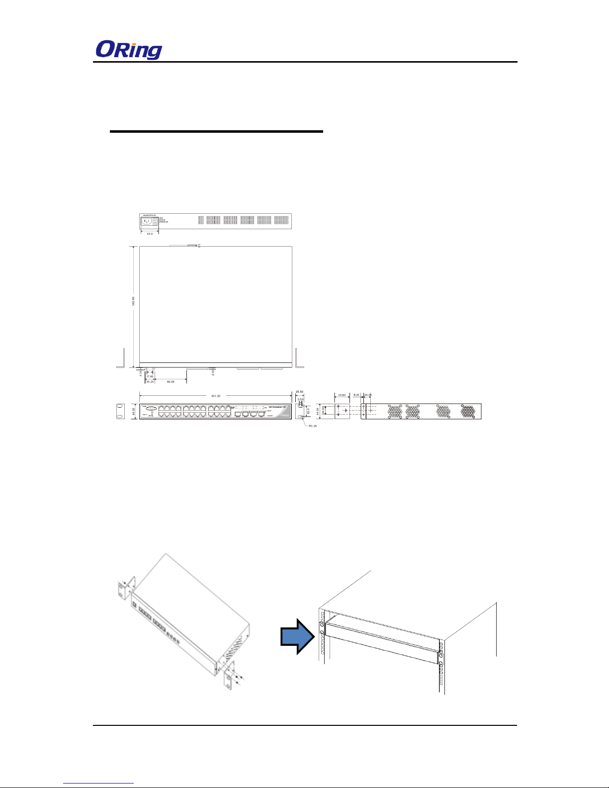
Dimensions: 431 (W) x 342 (D) x 44 (H) mm (16.97 x 13.47 x 1.73 inch)
RGPS-92222GCP-NP Series User Manual
ORing Industrial Networking Corp.
8
Hardware Overview
2.1 Front Panel
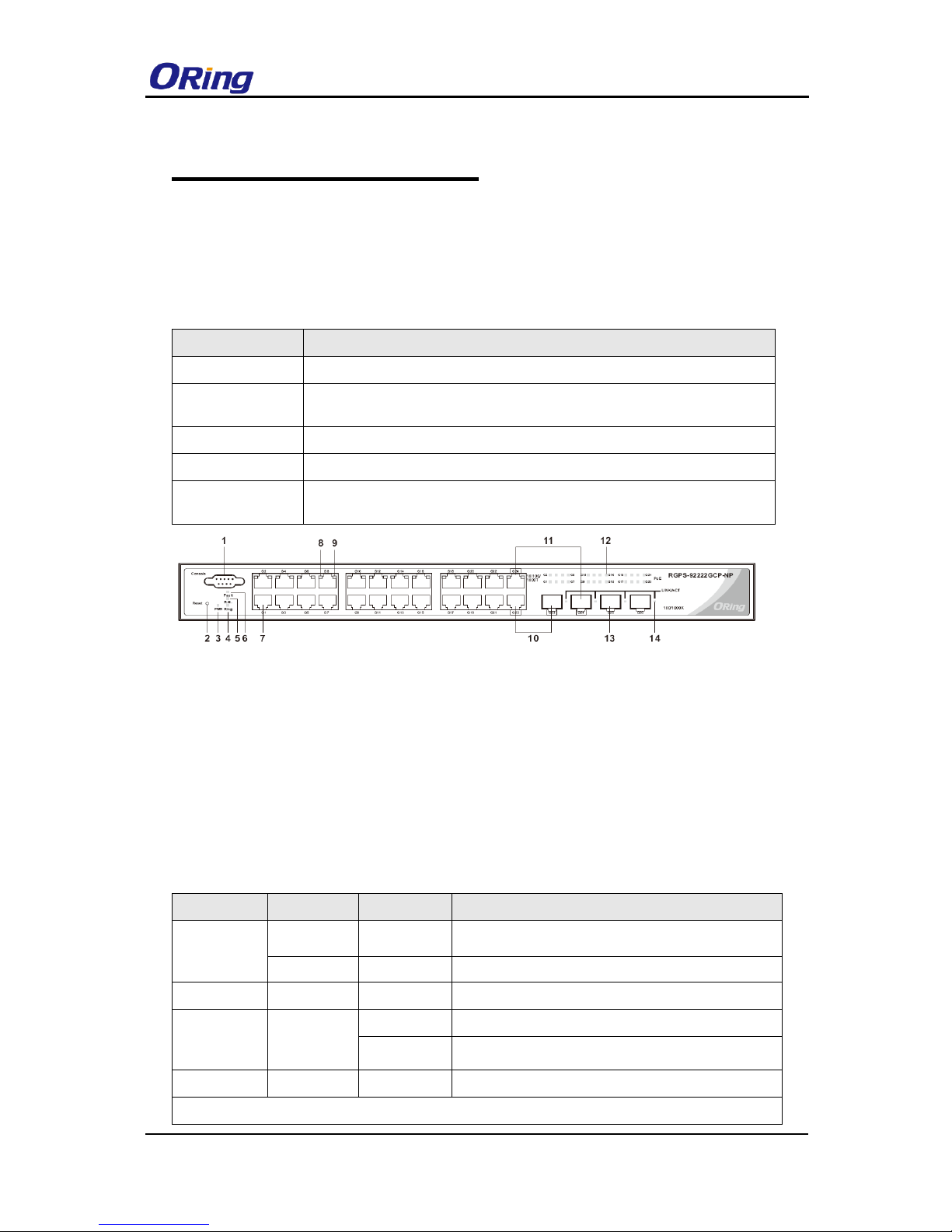
2.1.1 Ports and Connectors
The RGPS-92222GCP-NP series come with the following ports and connectors on the front
panel.
Port
Description
Ethernet ports
22 x 10/100/1000Base-T(X) IEEE802.3at P.S.E. ports
Combo ports
2 x Gigabit Combo ports with 10/100/1000Base-T(X) IEEE802.3at P.S.E. and
100/1000Base-X SFP ports
Fiber ports
2 x 100/1000Base-X SFP ports
Console port
1 x console port
Reset button
1 x reset button. Press the button for 3 seconds to reset and 5 seconds to
return to factory default.
2.1.2 LED
LED
Color
Status
Description
PWR
Green
On
System power on
Green
Blinking
Upgrading firmware
R.M
Green
On
Ring Master
Ring
Green
On
Ring enabled
Blinking
Ring structure is broken
Fault
Amber
On
Errors (power failure or port malfunctioning)
10/100/1000Base-T(X) RJ45 port
1. Console port
2. Reset button
3. Power indicator
4. Ring status LED
5. RM status LED
6. Fault indicator
7. LAN ports
8. LED for even Ethernet ports link / act status
9. LED for odd Ethernet ports link / act status
10. First Gigabit combo port
11. Second Gigabit combo port
12. PoE status LED for LAN ports
13. SFP port
14. LNK/ACT LED for SFP ports
RGPS-92222GCP-NP Series User Manual
ORing Industrial Networking Corp.
9
Link/Act
Green
On
Port connected
Blinking
Transmitting data
PoE
Green
On
PoE-enabled
100/1000Base-X SFP port
Link/Act
Green
On
Port connected
Blinking
Transmitting data
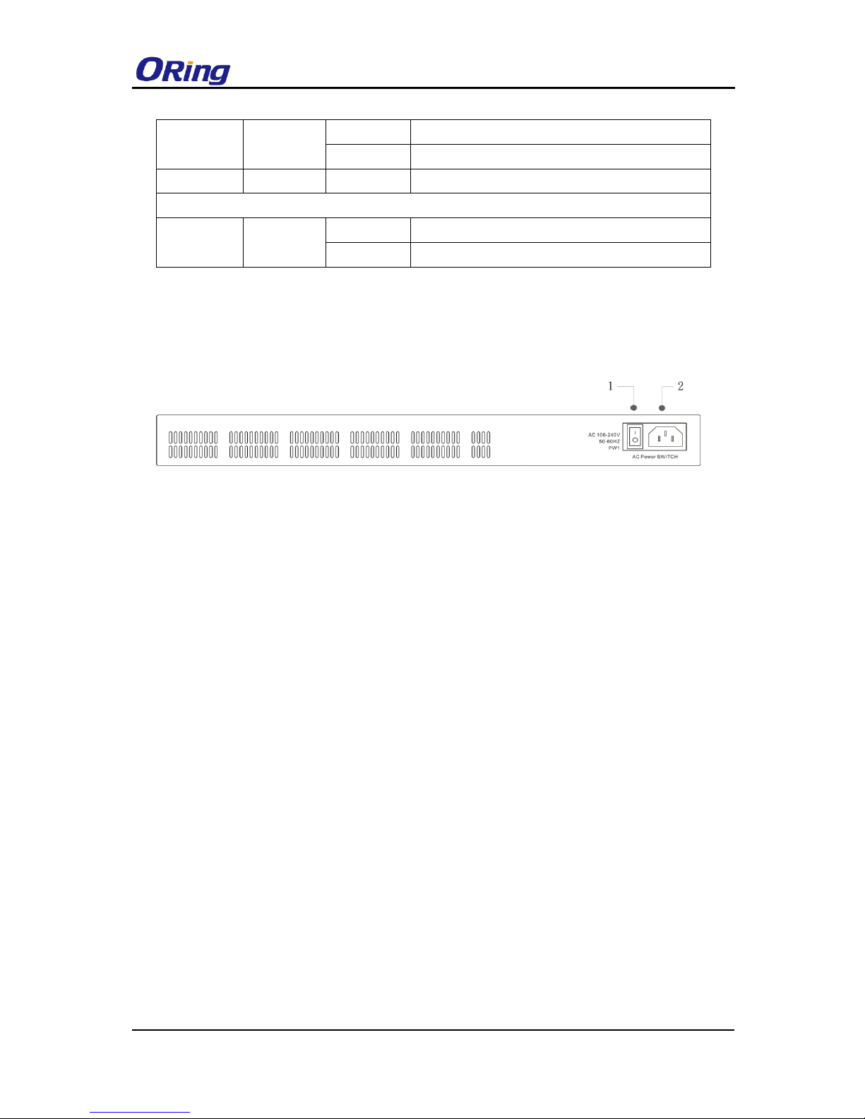
2.2 Rear Panel
On the rear panel of the switch sits two panel module slots and one terminal block. The
terminal block includes two power pairs for redundant power supply.
RGPS-92222GCP-NP/-LP /-P
1. Power switch
2. AC power input (100V~240V / 50~60Hz)
RGPS-92222GCP-NP Series User Manual
ORing Industrial Networking Corp.
10
Hardware Installation
3.1 Rack-mount Installation
The switch comes with two rack-mount kits to allow you to fasten the switch to a rack in any
environments.
Follow the following steps to install the switch to a rack.
Step 1: Install the mounting brackets to the left and right front sides of the switch using three
screws provided with the switch.
Step 2: With front brackets orientated in front of the rack, fasten the brackets to the rack using
two more screws.

RGPS-92222GCP-NP Series User Manual
ORing Industrial Networking Corp.
11
3.2 Wiring
Attention
1. Be sure to disconnect the power cord before installing and/or wiring your
switches.
2. Calculate the maximum possible current in each power wire and
common wire. Observe all electrical codes dictating the maximum
current allowable for each wire size.
3. If the current goes above the maximum ratings, the wiring could
overheat, causing serious damage to your equipment.
4. Use separate paths to route wiring for power and devices. If power
wiring and device wiring paths must cross, make sure the wires are
perpendicular at the intersection point.
5. Do not run signal or communications wiring and power wiring through
the same wire conduit. To avoid interference, wires with different signal
characteristics should be routed separately.
6. You can use the type of signal transmitted through a wire to determine
which wires should be kept separate. The rule of thumb is that wiring
sharing similar electrical characteristics can be bundled together
7. You should separate input wiring from output wiring
8. It is advised to label the wiring to all devices in the system
3.2.1 AC Power Connection
For power supply of RGPS-92222GCP-NP-LP / P, simply insert the AC power cable to the
power connector at the back of the switch and turn on the power switch. The input voltage is
100V~240V / 50~60Hz.
3.3 Connection
3.3.1 Cables
10/100BASE-T(X) & 1000BASE-T Pin Assignments
The device comes with standard Ethernet ports. According to the link type, the switch uses
CAT 3, 4, 5,5e UTP cables to connect to any other network devices (PCs, servers, switches,
routers, or hubs). Please refer to the following table for cable specifications.
Cable
Type
Max. Length
Connector
10BASE-T
Cat. 3, 4, 5 100-ohm
UTP 100 m (328 ft)
RJ-45

RGPS-92222GCP-NP Series User Manual
ORing Industrial Networking Corp.
12
100BASE-TX
Cat. 5 100-ohm UTP
UTP 100 m (328 ft)
RJ-45
1000BASE-T
Cat. 5/Cat. 5e 100-ohm UTP
UTP 100 m (328ft)
RJ-45
With 10/100/1000BASE-T(X) cables, pins 1 and 2 are used for transmitting data, and pins 3
and 6 are used for receiving data.
10/100Base-T(X) P.S.E. RJ-45 port
Pin Number
Assignment
#1
TD+ with PoE Power input +
#2
TD- with PoE Power input +
#3
RD+ with PoE Power input -
#6
RD- with PoE Power input -
10/100Base-T RJ-45 Pin Assignments
Pin Number
Assignment
1
TD+ 2 TD- 3 RD+
4
Not used
5
Not used
6
RD-
7
Not used
8
Not used
1000Base-T P.S.E. RJ-45 port
Pin Number
Assignment
#1
BI_DA+ with PoE Power input +
#2
BI_DA- with PoE Power input +
#3
BI_DB+ with PoE Power input -
#4
BI_DC+
#5
BI_DC-
#6
BI_DB- with PoE Power input -
#7
BI_DD+
#8
BI_DD-

RGPS-92222GCP-NP Series User Manual
ORing Industrial Networking Corp.
13
1000 Base-T RJ-45 Pin Assignments
Pin Number
Assignment
1
BI_DA+
2
BI_DA-
3
BI_DB+
4
BI_DC+
5
BI_DC-
6
BI_DB-
7
BI_DD+
8
BI_DD-
The series also support auto MDI/MDI-X operation. You can use a cable to connect the switch
to a PC. The table below shows the 10BASE-T/ 100BASE-TX MDI and MDI-X port pin outs.
10/100 Base-T(X) MDI/MDI-X Pin Assignments:
Pin Number
MDI port
MDI-X port
1
TD+(transmit)
RD+(receive)
2
TD-(transmit)
RD-(receive)
3
RD+(receive)
TD+(transmit)
4
Not used
Not used
5
Not used
Not used
6
RD-(receive)
TD-(transmit)
7
Not used
Not used
8
Not used
Not used
1000 Base-T MDI/MDI-X Pin Assignments:
Pin Number
MDI port
MDI-X port
1
BI_DA+
BI_DB+
2
BI_DA-
BI_DB-
3
BI_DB+
BI_DA+
4
BI_DC+
BI_DD+
5
BI_DC-
BI_DD-
6
BI_DB-
BI_DA-
7
BI_DD+
BI_DC+
8
BI_DD-
BI_DC-
Note: “+” and “-” signs represent the polarity of the wires that make up each wire pair.
RGPS-92222GCP-NP Series User Manual
ORing Industrial Networking Corp.
14
RS-232 console port wiring
The device can be managed via the console port using a RS-232 cable which can be found in
the package. Connect each end of the RS-232 cable to the switch and a PC respectively.
PC pin out (male) assignment
RS-232 with DB9 female connector
DB9 to RJ 45
Pin #2 RD
Pin #2 TD
Pin #2
Pin #3 TD
Pin #3 RD
Pin #3
Pin #5 GD
Pin #5 GD
Pin #5
3.3.2 SFP
The switch comes with fiber optical ports that can connect to other devices using SFP modules.
The fiber optical ports are in multi- or single-mode with LC connectors. Please remember that
the TX port of Switch A should be connected to the RX port of Switch B.
Switch A Switch B
3.3.3 O-Ring/O-Chain
O-RING
Fiber
RGPS-92222GCP-NP Series User Manual
ORing Industrial Networking Corp.
15
You can connect three or more switches to form a ring topology to gain network redundancy
capabilities through the following steps.
1. Connect each switch to form a daisy chain using an Ethernet cable.
2. Set one of the connected switches to be the master and make sure the port setting of each
connected switch on the management page corresponds to the physical ports connected. For
information about the port setting, please refer to 4.1.2 Configurations.
3. Connect the last switch to the first switch to form a ring topology.
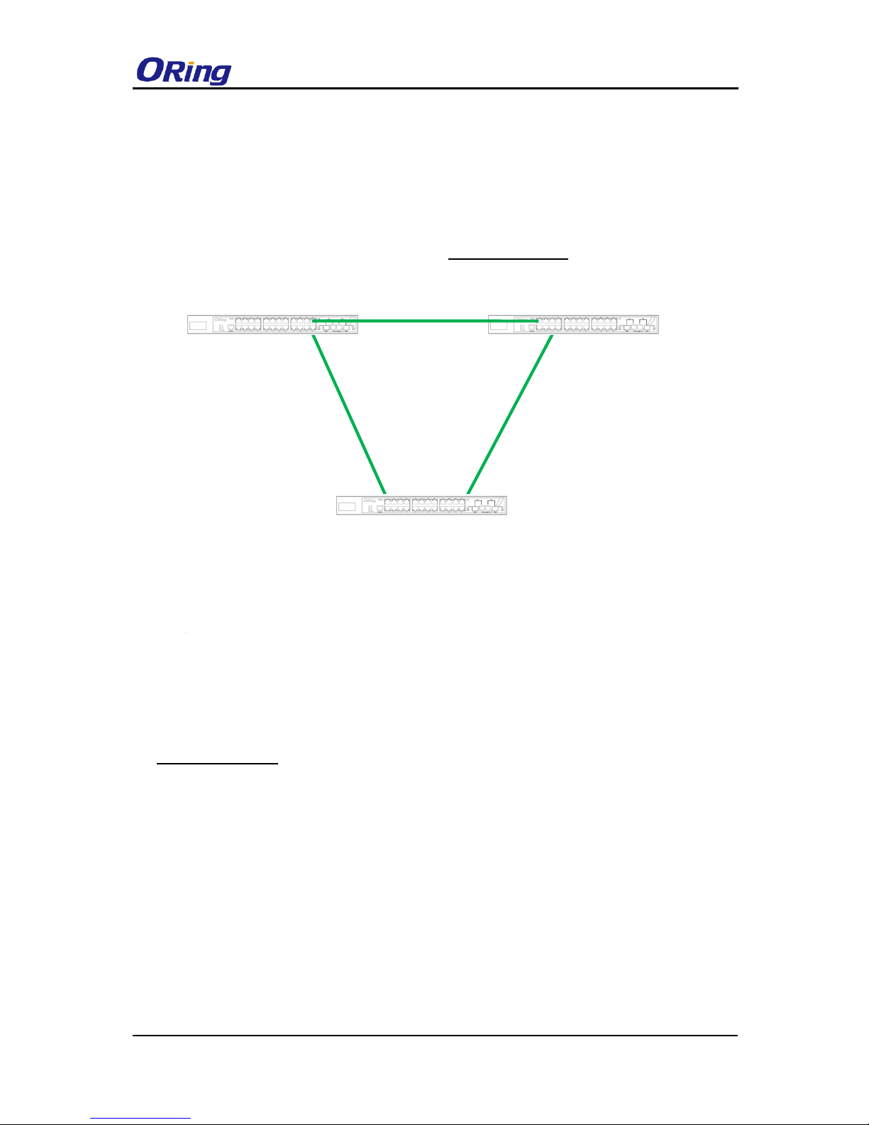
Coupling Ring
If you already have two O-Ring topologies and would like to connect the rings, you can form
them into a coupling ring. All you need to do is select two switches from each ring to be
connected, for example, switch A and B from Ring 1 and switch C and D from Ring 2. Decide
which port on each switch to be used as the coupling port and then link them together, for
example, port 1 of switch A to port 2 of switch C and port 1 of switch B to port 2 of switch D.
Then, enable Coupling Ring on the management page and select the coupling ring in
correspondence to the connected port. For more information on port setting, please refer to
4.1.2 Configurations. Once the setting is completed, one of the connections will act as the
main path while the other will act as the backup path.
O-Ring

RGPS-92222GCP-NP Series User Manual
ORing Industrial Networking Corp.
16
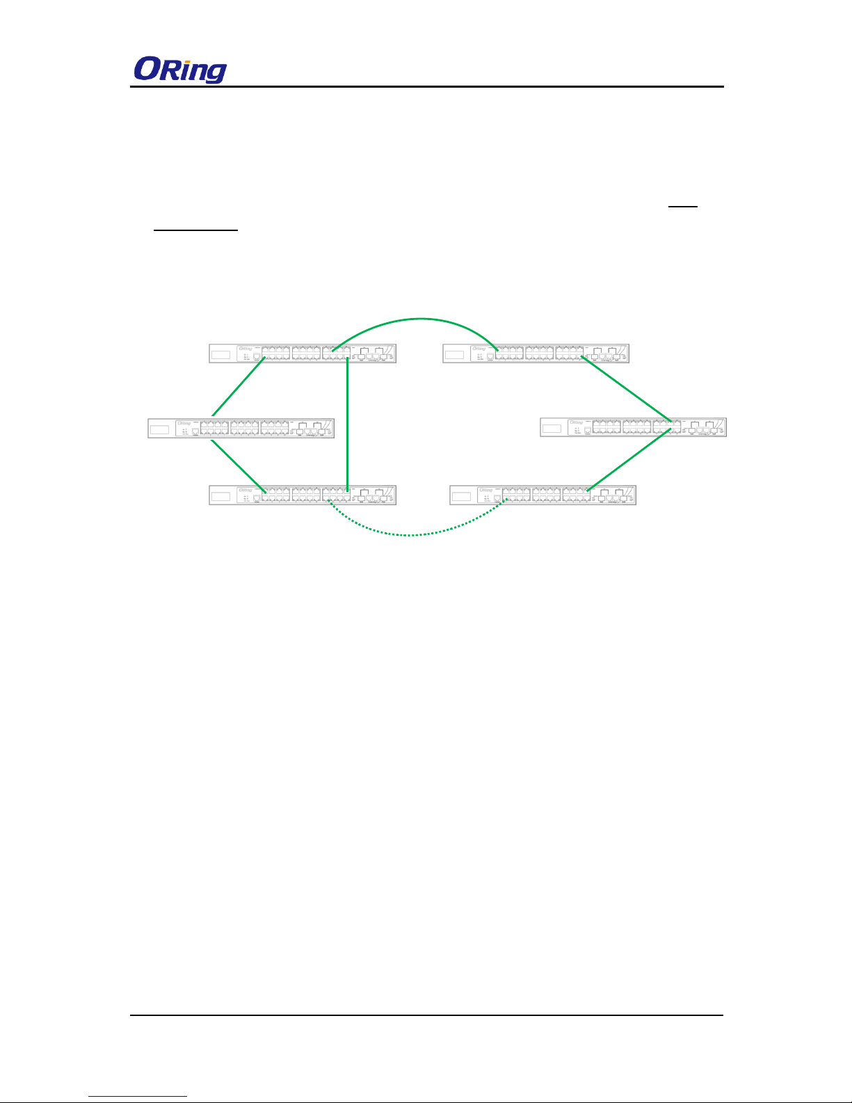
Dual Homing
If you want to connect your ring topology to a RSTP network environment, you can use dual
homing. Choose two switches (Switch A & B) from the ring for connecting to the switches in the
RSTP network (backbone switches). The connection of one of the switches (Switch A or B) will
act as the primary path, while the other will act as the backup path that is activated when the
primary path connection fails.
O-Chain
When connecting multiple O-Rings to meet your expansion demand, you can create an
O-Chain topology through the following steps.
RGPS-92222GCP-NP Series User Manual
ORing Industrial Networking Corp.
17
1. Select two switches from the chain (Switch A & B) that you want to connect to the O-Ring
and connect them to the switches in the ring (Switch C & D).
2. In correspondence to the ports connected to the ring, configure an edge port for both of the
connected switches in the chain by checking the box in the management page (see 4.1.2
Configurations).
3. Once the setting is completed, one of the connections will act as the main path, and the
other as the backup path.
Switch A
Switch B
Edge port
Edge port
Switch C
Switch D
O-Ring
RGPS-92222GCP-NP Series User Manual
ORing Industrial Networking Corp.
18
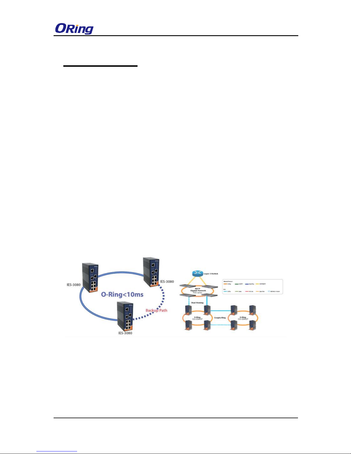
Redundancy
Redundancy for minimized system downtime is one of the most important concerns for
industrial networking devices. Hence, ORing has developed proprietary redundancy
technologies including O-Ring, O-RSTP, and Open-Ring featuring faster recovery time than
existing redundancy technologies widely used in commercial applications, such as STP, RSTP,
and MSTP. ORing’s proprietary redundancy technologies not only support different networking
topologies, but also assure the reliability of the network.
4.1 O-Ring
4.1.1 Introduction
O-Ring is ORing's proprietary redundant ring technology, with recovery time of less than 10
milliseconds and up to 250 nodes. The ring protocols identify one switch as the master of the
network, and then automatically block packets from traveling through any of the network’s
redundant loops. In the event that one branch of the ring gets disconnected from the rest of the
network, the protocol automatically readjusts the ring so that the part of the network that was
disconnected can reestablish contact with the rest of the network. The O-Ring redundant ring
technology can protect mission-critical applications from network interruptions or temporary
malfunction with its fast recover technology.
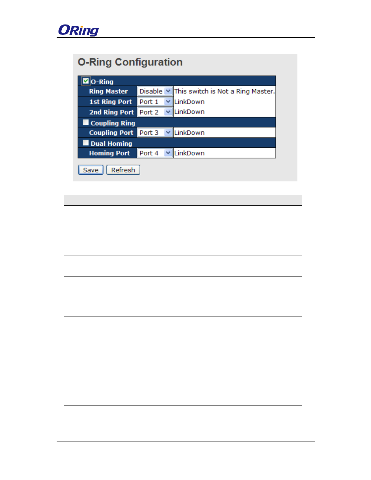
4.1.2 Configurations
O-Ring supports two ring topologies: Coupling Ring, and Dual Homing. You can configure
the settings in the interface below.
RGPS-92222GCP-NP Series User Manual
ORing Industrial Networking Corp.
19
Label
Description
Redundant Ring
Check to enable O-Ring topology.
Ring Master
Only one ring master is allowed in a ring. However, if more
than one switch are set to enable Ring Master, the switch with
the lowest MAC address will be the active ring master and the
others will be backup masters.
1st Ring Port
The primary port when the switch is ring master
2nd Ring Port
The backup port when the switch is ring master
Coupling Ring
Check to enable Coupling Ring. Coupling Ring can divide a
big ring into two smaller rings to avoid network topology
changes affecting all switches. It is a good method for
connecting two rings.
Coupling Port
Ports for connecting multiple rings. A coupling ring needs four
switches to build an active and a backup link.
Links formed by the coupling ports will run in active/backup
mode.
Dual Homing
Check to enable Dual Homing. When Dual Homing is
enabled, the ring will be connected to normal switches through
two RSTP links (ex: backbone Switch). The two links work in
active/backup mode, and connect each ring to the normal
switches in RSTP mode.
Apply
Click to apply the configurations.
Note: due to heavy loading, setting one switch as ring master and coupling ring at the same
time is not recommended.
RGPS-92222GCP-NP Series User Manual
ORing Industrial Networking Corp.
20
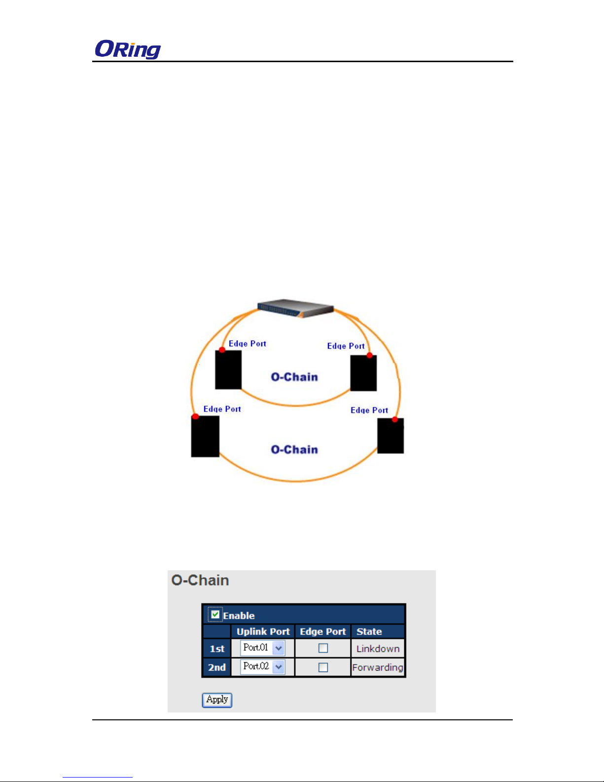
4.2 O-Chain
4.2.1 Introduction
O-Chain is ORing’s revolutionary network redundancy technology which enhances network
redundancy for any backbone networks, providing ease-of-use and maximum fault-recovery
swiftness, flexibility, compatibility, and cost-effectiveness in a set of network redundancy
topologies. The self-healing Ethernet technology designed for distributed and complex
industrial networks enables the network to recover in less than 10ms for up to 250 switches if
at any time a segment of the chain fails.
O-Chain allows multiple redundant rings of different redundancy protocols to join and function
together as a large and the most robust network topologies. It can create multiple redundant
networks beyond the limitations of current redundant ring technologies.
4.2.2 Configurations
O-Chain is very easy to configure and manage. Only one edge port of the edge switch needs
to be defined. Other switches beside them just need to have O-Chain enabled.
RGPS-92222GCP-NP Series User Manual
ORing Industrial Networking Corp.
21
Label
Description
Enable
Check to enable O-Chain function
1st Ring Port
The first port connecting to the ring
2nd Ring Port
The second port connecting to the ring
Edge Port
An O-Chain topology must begin with edge ports. The ports with a
smaller switch MAC address will serve as the backup link and RM LED
will light up.
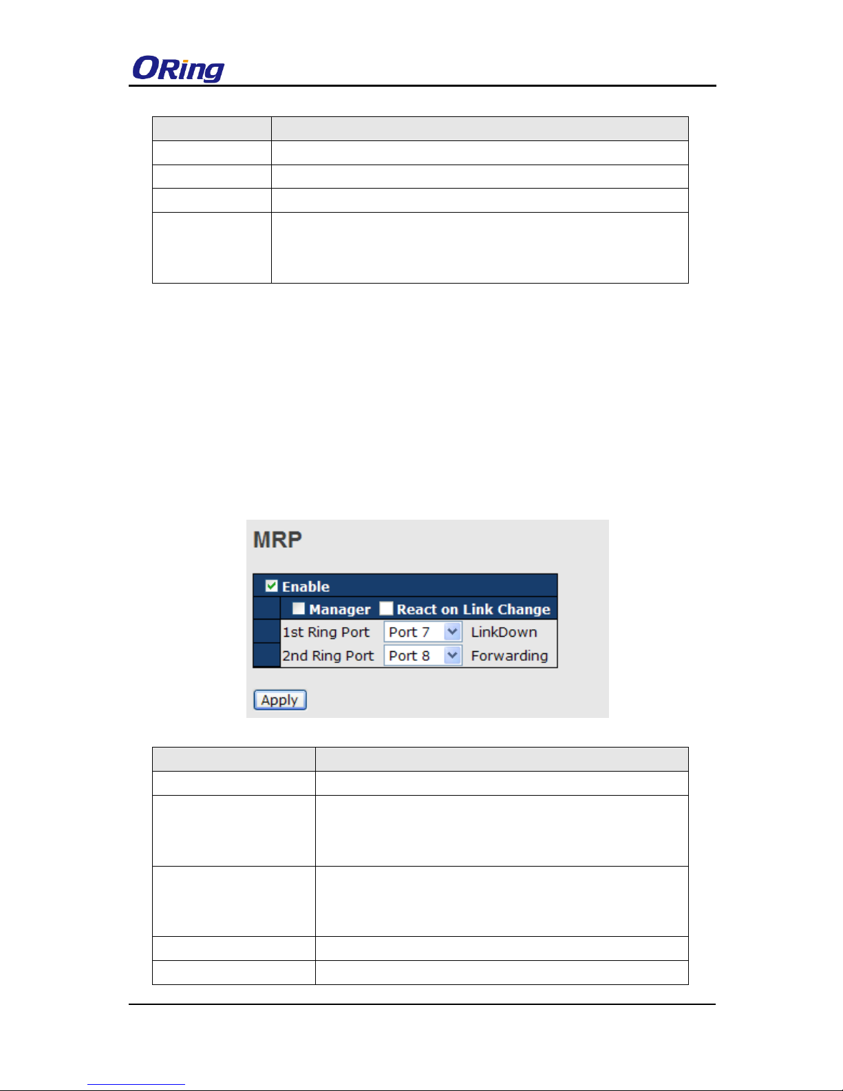
4.3 MRP
4.3.1 Introduction
MRP (Media Redundancy Protocol) is an industry standard for high-availability
Ethernet networks. MRP allowing Ethernet switches in ring configuration to recover from
failure rapidly to ensure seamless data transmission. A MRP ring (IEC 62439) can support up
to 50 devices and will enable a back-up link in 80ms (adjustable to max. 200ms/500ms).
4.3.2 Configurations
Label
Description
Enable
Enables the MRP function
Manager
Every MRP topology needs a MRP manager. One MRP
topology can only have a Manager. If two or more switches are
set to be Manager, the MRP topology will fail.
React on Link Change
(Advanced mode)
Faster mode. Enabling this function will cause MRP topology to
converge more rapidly. This function only can be set in MRP
manager switch.
1st Ring Port
Chooses the port which connects to the MRP ring
2nd Ring Port
Chooses the port which connects to the MRP ring

RGPS-92222GCP-NP Series User Manual
ORing Industrial Networking Corp.
22
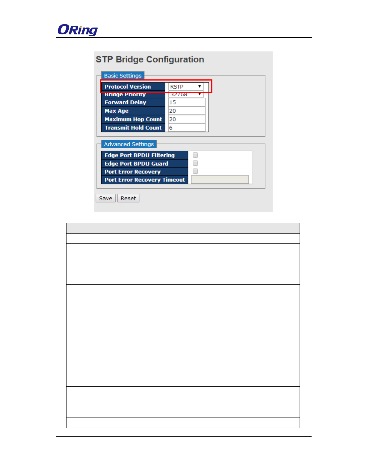
4.4 STP/RSTP/MSTP
4.4.1 STP/RSTP
STP (Spanning Tree Protocol), and its advanced versions RSTP (Rapid Spanning Tree
Protocol) and MSTP (Multiple Spanning Tree Protocol), are designed to prevent network loops
and provide network redundancy. Network loops occur frequently in large networks as when
two or more paths run to the same destination, broadcast packets may get in to an infinite loop
and hence causing congestion in the network. STP can identify the best path to the destination,
and block all other paths. The blocked links will stay connected but inactive. When the best
path fails, the blocked links will be activated. Compared to STP which recovers a link in 30 to
50 seconds, RSTP can shorten the time to 5 to 6 seconds. In other words, RSTP provides
faster spanning tree convergence after a topology changes. The switch supports STP and will
auto detect the connected device running on STP or RSTP protocols.
RSTP Bridge Setting
RGPS-92222GCP-NP Series User Manual
ORing Industrial Networking Corp.
23
Label
Description
Protocol Version
Select Spanning Tree type , support STP / RSTP / MSTP
Bridge Priority
(0-61440)
A value used to identify the root bridge. The bridge with the lowest
value has the highest priority and is selected as the root. If the
value changes, you must reboot the switch. The value must be a
multiple of 4096 according to the protocol standard rule
Forwarding Delay
Time (4-30)
The time of a port waits before changing from RSTP learning and
listening states to forwarding state. The valid value is between 4
through 30.
Max Age Time(6-40)
The number of seconds a bridge waits without receiving
Spanning-tree Protocol configuration messages before attempting
a reconfiguration. The valid value is between 6 through 40.
Maximum Hop Count
This defines the initial value of remaining Hops for MSTI
information generated at the boundary of an MSTI region. It
defines how many bridges a root bridge can distribute its BPDU
information to. Valid values are in the range 6 to 40 hops.
Transmit Hold Count
The number of BPDU's a bridge port can send per second. When
exceeded, transmission of the next BPDU will be delayed. Valid
values are in the range 1 to 10 BPDU's per second.
Edge Port BPDU
Control whether a port explicitly configured as Edge will transmit
RGPS-92222GCP-NP Series User Manual
ORing Industrial Networking Corp.
24
Filtering
and receive BPDUs.
Edge Port BPDU
Guard
Control whether a port explicitly configured as Edge will disable
itself upon reception of a BPDU. The port will enter the
error-disabled state, and will be removed from the active topology.
Port Error Recovery
Control whether a port in the error-disabled state automatically
will be enabled after a certain time. If recovery is not enabled,
ports have to be disabled and re-enabled for normal STP
operation. The condition is also cleared by a system reboot.
Port Error Recovery
Timeout
The time to pass before a port in the error-disabled state can be
enabled. Valid values are between 30 and 86400 seconds (24
hours).
NOTE: the calculation of the MAX Age, Hello Time, and Forward Delay Time is as follows:
2 x (Forward Delay Time value –1) > = Max Age value >= 2 x (Hello Time value +1)
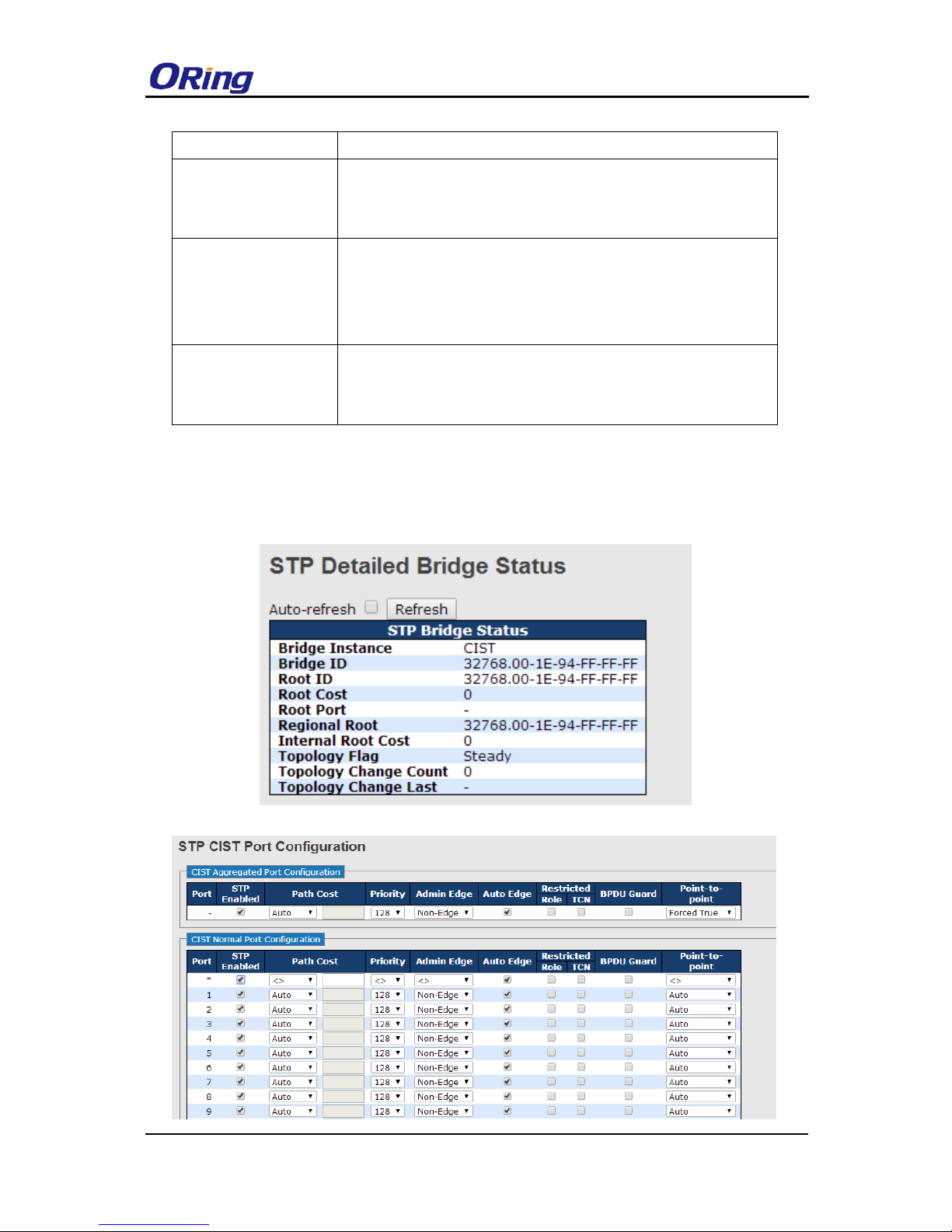
The following pages show the information of the root bridge, including its port status.

RGPS-92222GCP-NP Series User Manual
ORing Industrial Networking Corp.
25
Label
Description
Port
Port number
STP Enable
User can by port enable / disable STP Function
Path Cost Auto
User can setting Path Cost Auto or Specific
Path Cost Value
(1-200000000)
Controls the path cost incurred by the port. The Auto setting will set the
path cost as appropriate by the physical link speed, using the 802.1D
recommended values. Using the Specific setting, a user-defined value
can be entered. The path cost is used when establishing the active
topology of the network. Lower path cost ports are chosen as
forwarding ports in favour of higher path cost ports. Valid values are in
the range 1 to 200000000.
Port Priority
(0-240)
Decide which port should be blocked by priority in the LAN. The valid
value is between 0 and 240, and must be a multiple of 16
Admin Edge
Controls whether the operEdge flag should start as set or cleared.
(The initial operEdge state when a port is initialized).
Auto Edge
Controls whether the bridge should enable automatic edge detection
on the bridge port. This allows operEdge to be derived from whether
BPDU's are received on the port or not.
Restricted – Role
If enabled, causes the port not to be selected as Root Port for the CIST
or any MSTI, even if it has the best spanning tree priority vector. Such
a port will be selected as an Alternate Port after the Root Port has
been selected. If set, it can cause lack of spanning tree connectivity. It
can be set by a network administrator to prevent bridges external to a
core region of the network influence the spanning tree active topology,
possibly because those bridges are not under the full control of the
administrator. This feature is also known as Root Guard.
Restrcted -TCN
If enabled, causes the port not to propagate received topology change
notifications and topology changes to other ports. If set it can cause
temporary loss of connectivity after changes in a spanning tree's active
topology as a result of persistently incorrect learned station location
information. It is set by a network administrator to prevent bridges
external to a core region of the network, causing address flushing in
that region, possibly because those bridges are not under the full
control of the administrator or the physical link state of the attached
LANs transits frequently.
BPDU Guard
If enabled, causes the port to disable itself upon receiving valid
RGPS-92222GCP-NP Series User Manual
ORing Industrial Networking Corp.
26
BPDU's. Contrary to the similar bridge setting, the port Edge status
does not effect this setting.
Point to Point
Controls whether the port connects to a point-to-point LAN rather than
to a shared medium. This can be automatically determined, or forced
either true or false. Transition to the forwarding state is faster for
point-to-point LANs than for shared media.
Apply
Click to apply the configurations.
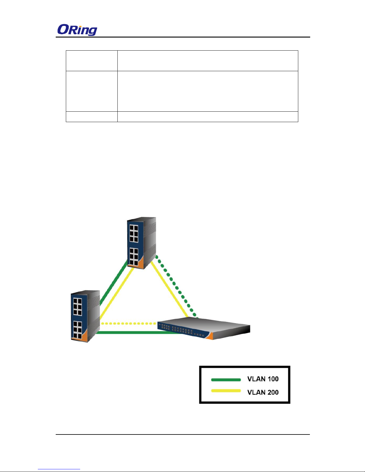
4.4.2 MSTP
Since the recovery time of STP and RSTP takes seconds, which is unacceptable in industrial
applications, MSTP was developed. The technology supports multiple spanning trees within a
network by grouping and mapping multiple VLANs into different spanning-tree instances,
known as MSTIs, to form individual MST regions. Each switch is assigned to an MST region.
Hence, each MST region consists of one or more MSTP switches with the same VLANs, at
least one MST instance, and the same MST region name. Therefore, switches can use
different paths in the network to effectively balance loads.
RGPS-92222GCP-NP Series User Manual
ORing Industrial Networking Corp.
27
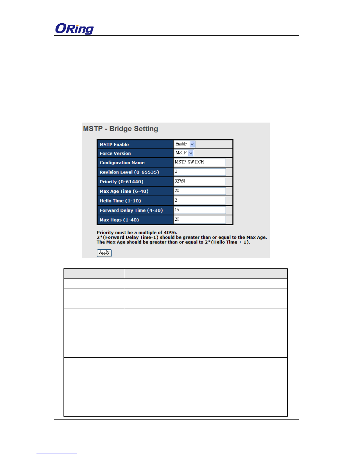
Bridge Settings
This page allows you to examine and change the configurations of current MSTI ports. A MSTI
port is a virtual port, which is instantiated separately for each active CIST (physical) port for
each MSTI instance configured and applicable for the port. The MSTI instance must be
selected before MSTI port configuration options are displayed.
Label
Description
MSTP Enable
Enables or disables MSTP function.
Force Version
Forces a VLAN bridge that supports RSTP to operate in an
STP-compatible manner.
Configuration Name
The name which identifies the VLAN to MSTI mapping. Bridges
must share the name and revision (see below), as well as the
VLAN-to-MSTI mapping configurations in order to share spanning
trees for MSTIs (intra-region). The name should not exceed 32
characters.
Revision Level
(0-65535)
Revision of the MSTI configuration named above. This must be
an integer between 0 and 65535.
Priority (0-61440)
A value used to identify the root bridge. The bridge with the lowest
value has the highest priority and is selected as the root. If the
value changes, you must reboot the switch. The value must be a
multiple of 4096 according to the protocol standard rule.

RGPS-92222GCP-NP Series User Manual
ORing Industrial Networking Corp.
28
Max Age Time(6-40)
The number of seconds a bridge waits without receiving
Spanning-tree Protocol configuration messages before attempting
a reconfiguration. The valid value is between 6 through 40.
Hello Time (1-10)
The time interval a switch sends out the BPDU packet to check
RSTP current status. The time is measured in seconds and the
valid value is between 1 through 10.
Forwarding Delay
Time (4-30)
The time of a port waits before changing from RSTP learning and
listening states to forwarding state. The valid value is between 4
through 30.
Max Hops (1-40)
An additional parameter for those specified for RSTP. A single
value applies to all STP within an MST region (the CIST and all
MSTIs) for which the bridge is the regional root.
Apply
Click to apply the configurations.
Bridge Port
Label
Description
Port No.
The number of port you want to configure
Priority (0-240)
Decide which port should be blocked by priority in the LAN. The
valid value is between 0 and 240, and must be a multiple of 16.
Path Cost
(1-200000000)
The path cost incurred by the port. The path cost is used when
establishing an active topology for the network. Lower path cost
ports are chosen as forwarding ports in favor of higher path cost
ports. The range of valid values is 1 to 200000000.
Admin P2P
Configures whether the port connects to a point-to-point LAN
rather than a shared medium. This can be configured
automatically or set to true or false manually. True means P2P
enabling. False means P2P disabling. Transiting to forwarding
RGPS-92222GCP-NP Series User Manual
ORing Industrial Networking Corp.
29
state is faster for point-to-point LANs than for shared media.
Admin Edge
Specify whether this port is an edge port or a nonedge port. An
edge port is not connected to any other bridge. Only edge ports
and point-to-point links can rapidly transition to forwarding state.
To configure the port as an edge port, set the port to True.
Admin Non STP
The port includes the STP mathematic calculation. True is not
including STP mathematic calculation, false is including the STP
mathematic calculation.
Apply
Click to apply the configurations.
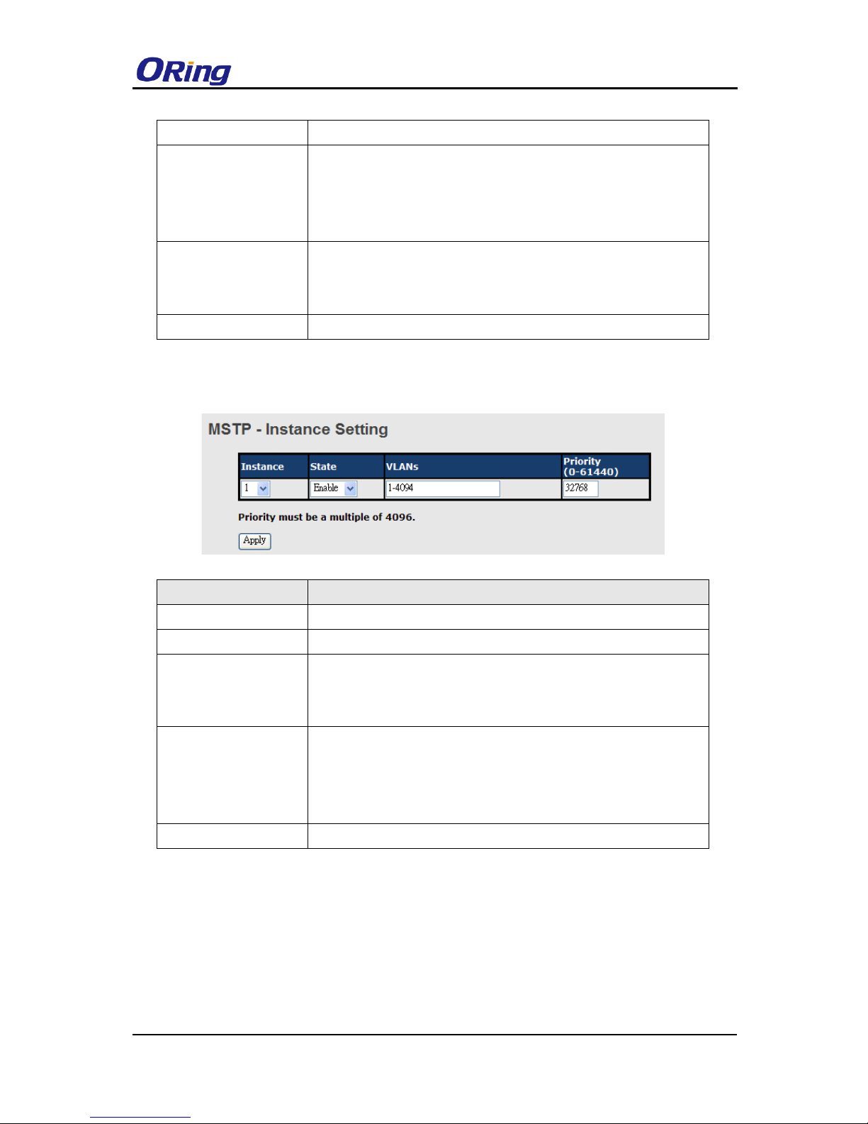
Instance Setting
This page allows you to change the configurations of current MSTI bridge instance.
Label
Description
Instance
Set the instance from 1 to 15
State
Enables or disables the instance
VLANs
The VLAN which is mapped to the MSTI. A VLAN can only be
mapped to one MSTI. An unused MSTI will be left empty (ex.
without any mapped VLANs).
Priority (0-61440)
A value used to identify the root bridge. The bridge with the lowest
value has the highest priority and is selected as the root. If the
value changes, you must reboot the switch. The value must be a
multiple of 4096 according to the protocol standard
Apply
Click to apply the configurations.
Port Priority
This page allows you to change the configurations of current MSTI bridge instance priority.
 Loading...