

ORiNG RGPS-9084GP-P Quick Installation Manual

Quick InstallationGuide
Version 1.0
Quick Installation Guide
Introduction
PRINTED ON RECYCLED PAPER
QIG
1907-2-29-RGPS9084GPP-1.0
The is managedPoE Ethernet switchwith eight Gigabit
P.S.E.ports and fourGigabit SFP ports.The P.S.E portscan transmit
electrical powerup to 30watts per port(240watts in totalbetween -40 ~
60 C and120watts in totalbetween 60 ~75 C) along withdata to remote
devices overstandard twisted-pair cables. The switch supports several
Ethernet redundancy technologies such as O-Ring (recovery time<30ms
over 250units of connection) and O-Chain topologies, as well as MSTP
protocol (RSTP/STP compatible) to protect mission-critical applications
from networkinterruptions or temporarymalfunctions with fastrecovery
technology.With a wideoperating temperature from-40 C to 75 C,the
device canbe managed centrallyvia ORing’s proprietaryOpen-Vision
management utilityas well asvia Web-based interfaces,Telnet, and
console (CLI).
RGPS-9084GP-P
o o
oo
Preparation
Before youbegin installing theswitch, make sureyou have allof the package
contents availableand a PCwith Microsoft InternetExplorer 6.0 orlater, for
using web-basedsystem management tools.
Elevated OperatingAmbient: If installed in a closed or multi-unit rack
assembly,the operating ambienttemperature of therack environment maybe
greater thanroom ambient. Therefore,consideration should begiven to
installing theequipment in anenvironment compatible withthe maximum
ambient temperature(Tma) specified bythe manufacturer.
Safety & Warnings
Dimension
Panel Layouts
1. Resetbutton
2. Consoleport
3. Powerindicator
4. Ringstatus LED
5. RMstatus LED
6. LANports
Front View
Rear View
Network Connection
Package Contents
Contents
QIG
CD
Screw (M4X6)
Powercord
Rack-mounted
kit(L&R)
Number
X1
X1
X6
X1
X1
RGPS-9084GP
-P
Pictures
MANAGED
Rack-Mount
GIGABIT
SWITCH
PoE
X1
7. LNK/ACTindicator for EthernetLAN ports
8. Speedindicator for EthernetLAN ports
9. PoEindicator
10. SFPport
11. LNK/ACTLED for SFPports
1 2
1. Powerswitch
2. ACpower input (100V~240V
/ 50~60Hz)
The serieshave standard Ethernetports. Accordingto the linktype, the switchuses CAT3, 4,
5,5e UTPcables to connectto any othernetwork devices (PCs,servers, switches, routers,or
hubs). Pleaserefer to thefollowing table forcable specifications.
Cable Typesand Specifications:
Cable Type Max. Length Conne ctor
10BASE-T Cat. 3, 4,5 100-ohm UTP 100m (328 ft) RJ-45
100BASE-TX Cat. 5100-ohmUTP UTP 100 m(328 ft) RJ-45
1000BASE- T Cat. 5 /Cat. 5e 100-ohm UTP UTP100 m (328 ft) RJ-4 5
For pinassignments for differenttypes of cables,please refer tothe following
tables.
1000Base-T P.S.E. RJ -45 port
Pin Number Assignment
#1 BI_DA+ with PoE Power in put +
#2
BI_DA- wit h PoE Powe r input +
#3
BI_DB+withPoE Powerinput -
#4
BI_DC+
#5
BI_DC-
#6
BI_DB- wit h PoE Power in put -
#7
BI_DD+
#8
BI_DD-
The device is shipped with the followingitems. If anyof these itemsis
missing ordamaged, please contactyour customer servicerepresentative
for assistance.
ReducedAir Flow:
Mechanical Loading:
Circuit Overloading:
Installation of the equipment in a rack should be such that the
amount of air flow required for safe operation of the equipment is not compromised.
Mounting of the equipment in the rack should be such that a
hazardous condition is not achieved due to uneven mechanical loading.
Consideration shouldbe given tothe connection ofthe equipment to
the supplycircuit and theeffect that overloadingof the circuitsmight have onovercurrent
protection andsupply wiring.Appropriate consideration ofequipment nameplate ratings
should beused when addressingthis concern.
Installation
Rack-mounting
Step 1:
Step 2:
Install leftand right frontmounting brackets tothe switch usingthree screws on each side.
With frontbrackets orientated infront of therack, fasten thebrackets to therack using two
more screws.
RGPS-9084GP-P
RGPS-9084GP-P
Managed Gigabit PoE Ethernet Switch
1000X
PWR
Ring
R.M.
44.00
443.70
58.00
42.70
26.70
24.00
24.00
30.20
3.90
R3.50
19.00
3.70
185.25
15.90
6.50
230.00
G1 G3 G5 G7
AC100-240V
50-60HZ
380.00 49.0
3.0
G9 G10 G11 G12
G1 G3 G5 G7
RGPS-9084GP-P
FullGigabitEthernetPoESwitch
Reset
PoE
115200,8,N,1
Console
LINK/ACT
2.65
PWR
Ring
R.M.
1000X
1000X
PWR
Ring
R.M.
G1 G3 G5 G7
G9 G10 G11 G12
G1 G3 G5 G7
RGPS-9084GP-P
FullGigabitEthernetPoESwitch
Reset
PoE
115200,8,N,1
Console
LINK/ACT
PWR
Ring
R.M.
1000X
2 3
4
5671 8
9
10
11
AC100-240V
50-60HZ
10/100Base-T(X) P.S.E RJ-45 Port
Pin Number Assignments
1 TD+ wit h PoE Power inp ut +
2 TD- with Po E Power input +
3 RD+ with P oE Power input -
4 Not used
5 Not used
6 RD-wit h PoE Power inp ut -
7 Not used
8 Not used
Note: and signsrepresent the polarityof the wiresthat make upeach wire pair.“+” “-”
Console Cable
X1
10/100Base-T(X) MDI/ MDI-X Pin Assignm ents:
PinNumber MDI port MDI-X port
1 TD+(transmit) RD+(receive)
2 TD- (transmit) RD-( receive)
3 RD+(receiv e) TD+(transmit)
4 Not used Not used
5 Not used Not used
6 RD-(receive) TD-(transmit)
7 Not used Not used
8 Not used Not used
1000Base-T M DI/MDI-X Pin Assignm ents
Pin Number MDI port MDI-X port
1 BI_ DA+ BI_DB+
2 BI_DA- BI_DB-
3 BI_ DB+ BI_DA+
4 BI_DC+ BI_DD+
5 BI_DC- BI _DD-
6 BI_DB- BI_DA-
7 BI_DD+ BI_DC+
8 BI_DD- BI _DC-
QIG
Quick InstallationGuide
PRINTED ON RECYCLED PAPER
Version 1.0
Quick Installation Guide
Configurations
After installingthe switch andconnecting cables, startthe switch by
turning onpower. Thegreen power LEDshould turn on.
LED indication table
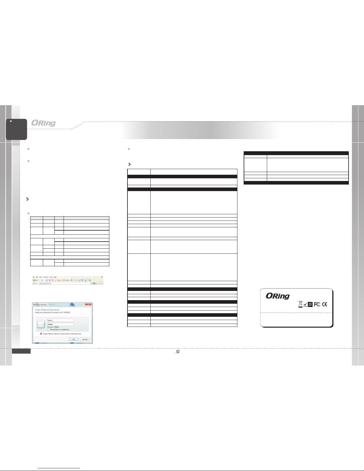
1. Launchthe Internet Explorerand type inIP address ofthe switch.The
default staticIP address is192.168.10.1
RegulatoryApprovals
FCCPart 15, CISPR(EN55022) class AEMI
EN61000-4-2(ESD)
EN61000-4-3(RS)
EN61000-4-4(EFT)
EN61000-4-5(Surge)
EN61000-4-6(CS)
EN61000-4-8
EN61000-4-11
EMS
Warranty
5years
Warranty
5years
MANAGED
Rack-Mount
GIGABIT
SWITCH
PoE
ORing IndustrialNetworking Corp.
Copyright© 2015 ORing
All rightsreserved.
TEL: +886-2-2218-1066
FAX:+886-2-2218-1014
Website: www.oring-networking.com
E-mail: support@oring-networking.com
IEC60068-2-27Shock
IEC60068-2-32FreeFall
IEC60068-2-6Vibration
2. Login with defaultuser name andpassword (both are ). After
logging in,you should see the following screen. For more information
on configurations, please referto the usermanual. For informationon
operating theswitch using ORing’sOpen-Vision management utility, please
go toORing website.
admin
Wiring
For powersupply, simplyinsert the ACpower cable tothe power
connector atthe back ofthe switch and turn on the power switch. The
input voltage is100~240V / 50~60Hz.range AC
Power inputs
Grounding andwire routing helplimit the effectsof noise dueto
electromagnetic interference(EMI). Run theground connection fromthe
ground screwsto the groundingsurface prior toconnecting devices.
Grounding
Resetting
Toreboot the switch,press the Reset button for2-3 seconds.
Torestore the switchconfigurations back tothe factory defaults,press the Reset button for5 seconds.
LED Color Status Descripti on
PWR Green On System power is connec ted
R.M Green On Device is operati ng as a ring m aster
On R ing is enabl ed and device i s running in Ring mod e
Ring Green
Blinking Ring structureis broken
10/100/1000Bas e-T(X) RJ45 por t
On Port is lin ked
Link/Act Green
Blinking Transmittingdata
Amber On Port i s linked and runs at 10/100M bps
Speed
Green On Port is li nked and run s at 1000Mbps
PoE Blue On Power is suppl ied over Ether net cable
SFP port
On Port is lin ked
Link/Act Green
Blinking Transmittingdata
RGPS-9084GP-P
RGPS-9084GP-P
Managed Gigabit PoE Ethernet Switch
Specifications
ORingSwitch Model
PhysicalPorts
Technology
EthernetStandards
10/100/1000Base-T(X)with
P.S.E.PortsinRJ45Auto
MDI/MDIX
SwitchProperties
SecurityFeatures
DeviceBinding security feature
Enable/disableports, MAC basedport security
Portbased network accesscontrol (802.1x)
VLAN(802.1Q) to segregatean secure networktraffic
Radiuscentralized password management
SNMPv3encrypted authentication andaccess security
Https/ SSH enhancenetwork security
RGPS-9084GP-P
8
-40~60 C: provided total240watts maximum, 60~ 75 C :provided total 120wattsmaximum
o o
IEEE802.3 for 10Base-T
IEEE802.3u for 100Base-TX
IEEE802.3z for 1000Base-X
IEEE802.3ab for 1000Base-T
IEEE802.3x for Flowcontrol
IEEE802.3ad for LACP(Link Aggregation ControlProtocol )
IEEE802.1p for COS(Class of Service)
IEEE802.1Q for VLANTagging
IEEE802.1w for RSTP(Rapid Spanning TreeProtocol)
IEEE802.1x for Authentication
IEEE802.1AB for LLDP(Link Layer DiscoveryProtocol)
IEEE802.3af/at PoE specification
Switchlatency: 7 us
Switchbandwidth: 24Gbps
Max.Number of AvailableVLANs: 256
IGMPmulticast groups: 128for each VLAN
Portrate limiting: UserDefine
MACTable
8K
Processing
Store-and-Forward
PriorityQueues
8
Jumboframe Upto9.6K Bytes
100/1000Base-XSFP Port
4
PacketBuffer
4Mbits
SoftwareFeatures
STP/RSTP/MSTP(IEEE 802.1D/w/s)
RedundantRing (O-Ring) withrecovery time lessthan 30ms over250 units
TOS/Diffservsupported
Qualityof Service (802.1p)for real-time traffic
VLAN(802.1Q) with VLANtagging
IGMPSnooping
IP-basedbandwidth management
Application-basedQoS management
DOS/DDOSauto prevention
Portconfiguration, status, statistics,monitoring, security
DHCPServer/Client
SMTPClient
ModbusTCP
DNSclient proxy
NTPserver
RS-232Serial Console Port
NetworkRedundancy
O-Ring,Open-Ring, O-Chain, FastRecovery, MRP,MSTP (RST/STPcompatible)
RS-232in RJ45 connectorwith console cable.115200bps, 8, N,1 (support backupunit DBU-01)
Power
Powerconsumption(Typ.)
17Watts (PoE outputnot included)
Overloadcurrent protection
Present
Overloadcurrent protection
100~240VACwith power socket
Environmental
-40to85C(-40to185F)
oo
StorageTemperature
OperatingTemperature
PhysicalCharacteristic
Dimension(WxDxH)
Weight (g)
3730g
5%to 95% Non-condensing
OperatingHumidity
Enclosure
19inches rack mountable
443.7(W) x 230(D) x 44(H) mm (17.46x 9.05 x1.73 inches)
-40to75C(-40to167F)
oo
Console Port Pin Definition
The devicecan be managed via consoleports using theRJ-45 cable provided.You can
connect theport to aPC using anConsole cable providedto perform management
 Loading...