

ORiNG RES-P3242GCL User Manual
Industrial IEC 61850-3
Management Ethernet Switch
RES-P3242GCL SERIES User’s Manual
Version 2.0
JUN, 2012
ORing Industrial Networking Corp.
Website: www.oring-networking.com
E-mail: support@oring-networking.com

RES-P3242GCL SERIES User’s Manual
1
Table of Content
Getting to Know Your Switch ............................................................................................................ 4
1.1 About the RES-P3242GCL SERIES Industrial Switch .................................................. 4
1.2 Software Features .............................................................................................................. 4
1.3 Hardware Features ............................................................................................................. 4
Hardware Overview ............................................................................................................................. 0
2.1 Front Panel .......................................................................................................................... 0
2.2 Power Panel ........................................................................................................................ 1
2.3 Rack mount kit assembly ................................................................................................... 2
Cables ..................................................................................................................................................... 3
3.1 Ethernet Cables .................................................................................................................. 3
3.1.1 100BASE-TX/10BASE-T Pin Assignments ..................................................................... 3
3.2 SFP ....................................................................................................................................... 5
3.3 Console Cable ..................................................................................................................... 5
WEB Management ............................................................................................................................... 6
4.1 Configuration by Web Browser ......................................................................................... 6
4.1.1 About W eb-based Management ........................................................................................ 6
4.1.2 System Information .......................................................................................................... 8
4.1.3 Basic setting ...................................................................................................................... 9
4.1.3.2 Admin Password ..................................................................................................... 9
4.1.3.3 IP Setting ............................................................................................................... 10
4.1.3.4 SNTP (Time) ......................................................................................................... 11
4.1.3.5 LLDP ..................................................................................................................... 14
4.1.3.6 Backup & Restore ................................................................................................. 14
4.1.3.7 Upgrade Firmware ................................................................................................ 16
4.1.3.8 Broadcast storm filter ............................................................................................ 16
4.1.3.9 Aging Time ........................................................................................................... 17
4.1.3.10 Jumbo Frame ......................................................................................................... 17
4.1.4 Redundancy .................................................................................................................... 17
4.1.4.1 O-Ring ................................................................................................................... 17
4.1.4.2 OPEN-Ring ........................................................................................................... 18
4.1.4.3 O-RSTP ................................................................................................................. 19
4.1.4.4 RSTP ..................................................................................................................... 20
4.1.4.5 MSTP .................................................................................................................... 23

RES-P3242GCL SERIES User’s Manual
2
4.1.5 Multicast ......................................................................................................................... 28
4.1.5.1 IGMP Snooping ..................................................................................................... 28
4.1.5.2 MVR ..................................................................................................................... 29
4.1.5.3 Multicast Filter ...................................................................................................... 29
4.1.6 Port Setting ..................................................................................................................... 31
4.1.6.1 Port Control ........................................................................................................... 31
4.1.6.2 Port Status ............................................................................................................. 31
4.1.6.3 Port Alias ............................................................................................................... 32
4.1.6.4 Rate Limit ............................................................................................................. 32
4.1.6.5 Port Trunk ............................................................................................................. 33
4.1.6.6 Loop Guard ........................................................................................................... 35
4.1.7 VLAN ............................................................................................................................. 36
4.1.7.1 VLAN Setting ....................................................................................................... 36
4.1.7.2 VLAN Setting – Port Based .................................................................................. 38
4.1.8 Traffic Prioritization ....................................................................................................... 40
4.1.9 DHCP Server .................................................................................................................. 42
4.1.9.1 DHCP Server – Setting.......................................................................................... 42
4.1.9.2 DHCP Server – Client List .................................................................................... 43
4.1.9.3 DHCP Server – Port and IP bindings .................................................................... 43
4.1.10 SNMP ........................................................................................................................ 44
4.1.10.1 SNMP –System Setting ......................................................................................... 44
4.1.10.2 SNMP –Trap Setting ............................................................................................. 45
4.1.10.3 SNMP – SNMPv3 Setting ..................................................................................... 46
4.1.11 Security ...................................................................................................................... 49
4.1.11.1 Access Control List ............................................................................................... 49
4.1.11.2 IP Security ............................................................................................................. 50
4.1.11.3 Static MAC Forwarding ........................................................................................ 51
4.1.11.4 MAC Blacklist ...................................................................................................... 52
4.1.11.5 802.1x .................................................................................................................... 52
4.1.12 Warning ...................................................................................................................... 55
4.1.12.1 System Alarm ........................................................................................................ 56
4.1.13 Monitor and Diag ....................................................................................................... 60
4.1.13.1 System EventLog .................................................................................................. 60
4.1.13.2 MAC Address Table .............................................................................................. 61
4.1.13.3 Port Overview ....................................................................................................... 62
4.1.13.4 Port Counters ......................................................................................................... 63
4.1.13.5 Port Monitoring ..................................................................................................... 65

RES-P3242GCL SERIES User’s Manual
3
4.1.14 Save Configuration .................................................................................................... 66
4.1.15 Factory Default .......................................................................................................... 66
4.1.16 System Reboot ........................................................................................................... 67
Command Line Interface Management ........................................................................................ 68
5.1 About CLI Management ................................................................................................. 68
5.2 Commands Set List—System Commands Set ................................................................ 73
5.3 Commands Set List—Port Commands Set ..................................................................... 75
5.4 Commands Set List—Trunk command set ..................................................................... 77
5.5 Commands Set List—VLAN command set .................................................................... 79
5.6 Commands Set List—Spanning Tree command set ........................................................ 80
5.7 Commands Set List—QoS command set ........................................................................ 82
5.8 Commands Set List—IGMP command set ..................................................................... 83
5.9 Commands Set List—MAC/Filter Table command set .................................................. 84
5.10 Commands Set List—SNMP command set .................................................................... 84
5.11 Commands Set List—Port Mirroring command set ....................................................... 85
5.12 Commands Set List—802.1x command set .................................................................... 86
5.13 Commands Set List—TFTP command set ...................................................................... 88
5.14 Commands Set List—SYSLOG, SMTP, EVENT command set ..................................... 89
5.15 Commands Set List—SNTP command set ..................................................................... 91
5.16 Commands Set List—O-Ring command set ................................................................... 92
Technical Specifications .................................................................................................................. 93

RES-P3242GCL SERIES User’s Manual
4
Getting to Know Your Switch
1.1 About the RES-P3242GCL SERIES Industrial
Switch
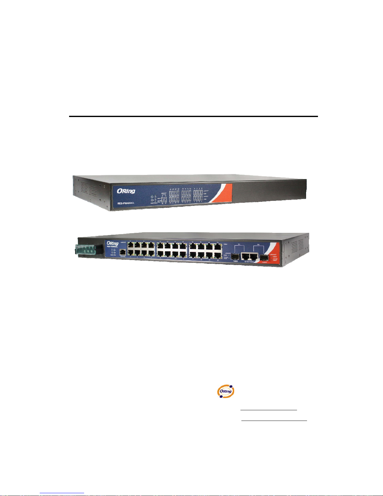
RES-P3242GCL SERIES are powerful managed indu strial switches for power station
applications which have many features. RES-P3242GCL SERIES pass the IEC 61850-3 and
IEEE 1613 certification. They can be managed by WEB, TELNET, Console or other
third-party SNMP software as well. Besides, these switches can be managed by a useful
utility that we called Open-Vision.
Open-Vision is powerful network management so ftware. With its friendly and powerful
interface, you can easily configure multiple switches at the same time, and monitor switches’
status.
1.2 Software Features
World’s fastest Redundant Ethernet Ring (Recovery time < 10ms over 250 units
connection)
Supports Ring Coupling, Dual Homing, RSTP over O-Ring
Supports SNMPv1/v2/v3 & RMON & Port base/802.1Q VLAN Network Management
Event notification by Email, SNMP trap and Relay Output
Web-based ,Telnet, Console, CLI configuration
Enable/disable ports, MAC based port security
Port based network access control (802.1x)
VLAN (802.1Q ) to segregate and secure network traffic
SNMPv3 encrypted authentication and access security
RSTP (802.1w)
Quality of Service (802.1p) for real-time traffic
Port configuration, status, statistics, mirroring, security
1.3 Hardware Features
Isolation redundant power inputs with 12 ~ 36VDC or 36 ~ 72VDC or 100 ~ 240VAC
power supply range
Operating Temperature:: -40 to 85
o
C
Operating Humidity: 5% to 95%, non-condensing
8 x 10/100Base-T(X) Ethernet ports

RES-P3242GCL SERIES User’s Manual
5
2 x 10/100/1000Base-T(X) and 1000Base-X SFP ports on combo port
1 x Console Port
Dimensions(W x D x H) : 443.7 mm(W)x 262.7 mm( D )x 44 mm(H)
19 inches rack mountable
Hardware Overview
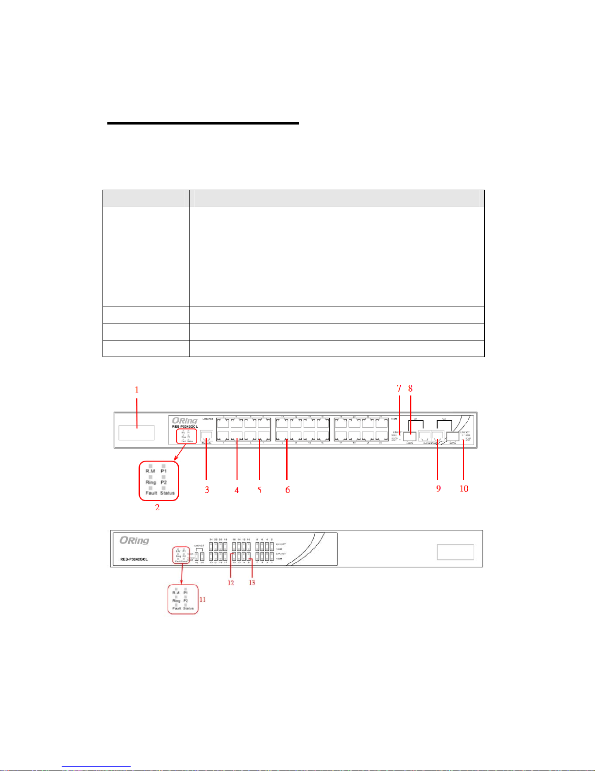
2.1 Front Panel
The following table describes the labels that stick on the RES-P3242GCL SERIES.
Port Description
10/100 RJ-45 fast
Ethernet ports
24 x 10/100Base-T(X) RJ-45 fast Ethernet ports support
auto-negotiation.
Default Setting :
Speed: auto
Duplex: auto
Flow control : disable
Gigabit port
2 x 10/100/1000Base-T(X) Gigabit ports (combo)
Fiber port
2 x 1000Base-X on SFP ports (combo)
Console
Use RS-232 cable to manage switch
1. Power inputs .
2. LED Status :
P1 LED for PWR1. When the PWR1 links, the green led will be light on.
P2 LED for PWR2. When the PWR2 links, the green led will be light on.
Status LED for System Status. When the system is ready, the green led will be light on.
RES-P3242GCL SERIES User’s Manual
1
R.M LED for Ring master. When the LED light on, it means that the switch is the ring
master of O-Ring.
Ring LED for Ring. When the LED light on, it means the O-Ring is activated.
Fault LED for Fault Relay. When the fault occurs, the amber LED will be light on.
3. RS-232 Console Port. Set connection at 9600bps, 8N1.
4. 10/100Base-T(X) Ethernet ports.
5. LED for Ethernet ports Link status.
6. LED for Ethernet ports ACT status.
7. LED for Combo SFP ports Link / ACT status.
8. 1000Base-X fiber port in SFP socket.
9. 10/100/1000Base-T(X) Ethernet port.
10. LED for Combo Copper ports Link / ACT status.
11. LED Status
P1 LED for PWR1. When the PWR1 links, the green led will be light on.
P2 LED for PWR2. When the PWR2 links, the green led will be light on.
Status LED for System Status. When the system is ready, the green led will be light on.
R.M LED for Ring master. When the LED light on, it means that the switch is the ring
master of O-Ring.
Ring LED for Ring. When the LED light on, it means the O-Ring is activated.
Fault LED for Fault Relay. When the fault occurs, the amber LED will be light on.
12. LED for Combo SFP ports Link / ACT status.
13. LED for Combo Copper ports Link / ACT status.
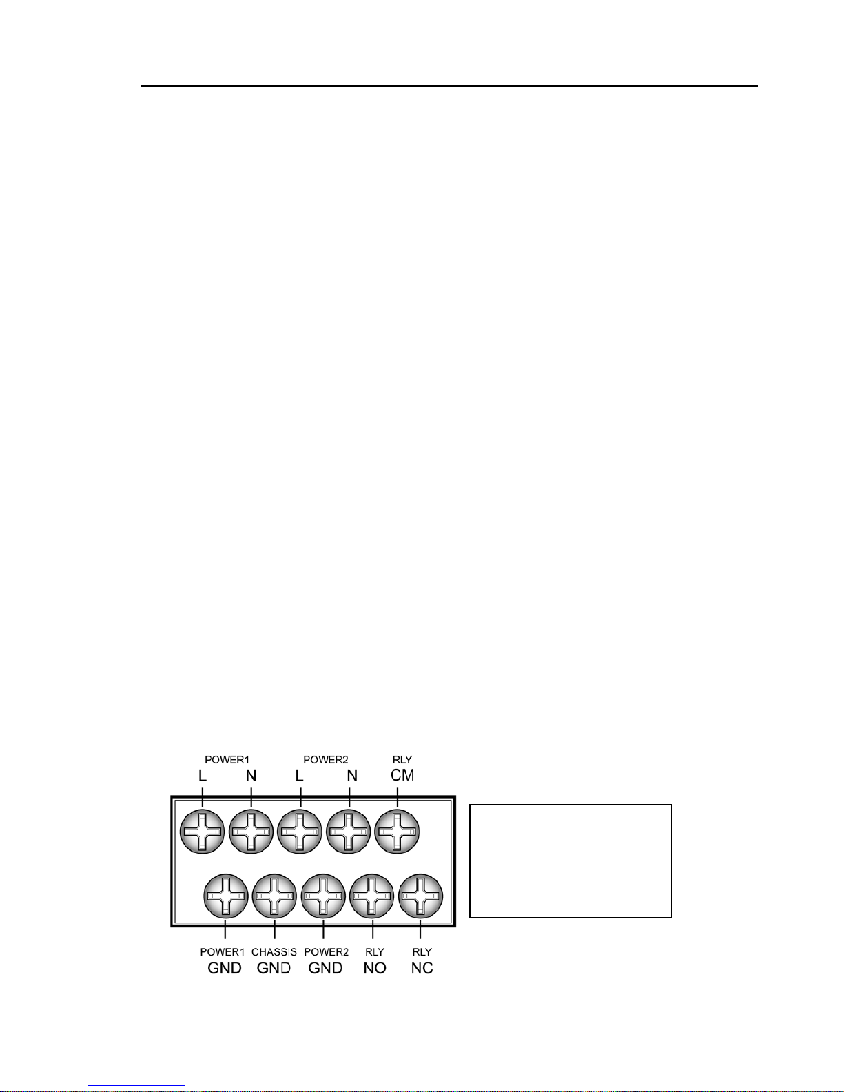
2.2 Power Panel
RES-P3242GCL SERIES are power redundant switches, supports two power inputs.
Note :
RL Y COM– Relay Com
RL Y NO – Relay Normal Open
RL Y NC – Relay Normal Close

RES-P3242GCL SERIES User’s Manual
2
2.3 Rack mount kit assembly
You can find the rack mount kit and the screws in the packing box. Please assembly the rack
mount kit on the switch with screws as below picture.

RES-P3242GCL SERIES User’s Manual
3
Cables
3.1 Ethernet Cables
RES-P3242GCL SERIES switches have standard Ethernet ports. According to the link
type, these switches use CAT 3, 4, 5,5e UTP cables to connect to any other network device
(PCs, servers, switches, routers, or hubs). Please refer to the following table for cable
specifications.
Cable Types and Specifications
Cable Type Max. Length Connector
10BASE-T Cat.3, 4, 5 100-ohm UTP 100 m (328 ft) RJ-45
100BASE-TX Cat.5 100-ohm UTP UTP 100 m (328 ft) RJ-45
1000BASE-T Cat.5/Cat.5e 100-ohm UTP UTP 100 m (328ft) RJ-45
3.1.1 100BASE-TX/10BASE-T Pin Assignments
With 100BASE-TX/10BASE-T cable, pins 1 and 2 are used for transmitting data, and
pins 3 and 6 are used for receiving data.
10/100 Base-T RJ-45 Pin Assignments
Pin Number Assignment
1 TD+
2 TD3 RD+
4 Not used
5 Not used
6 RD7 Not used
8 Not used

RES-P3242GCL SERIES User’s Manual
4
1000 Base-T RJ-45 Pin Assignments
Pin Number Assignment
1 BI_DA+
2 BI_DA3 BI_DB+
4 BI_DC+
5 BI_DC6 BI_DB7 BI_DD+
8 BI_DD-
The RES-P3242GCL SERIES switches support auto MDI/MDI-X operation. You can
use a straight-through cable to connect PC to switch. The following table below shows
the 10BASE-T/ 100BASE-TX MDI and MDI-X port pin outs.
10/100 Base-T MDI/MDI-X pins assignment
Pin Number MDI port MDI-X port
1 TD+(transmit) RD+(receive)
2 TD-(transmit) RD-(receive)
3 RD+(receive) TD+(transmit)
4 Not used Not used
5 Not used Not used
6 RD-(receive) TD-(transmit)
7 Not used Not used
8 Not used Not used
1000 Base-T MDI/MDI-X pins assignment
Pin Number MDI port MDI-X port
1 BI_DA+ BI_DB+
2 BI_DA- BI_DB3 BI_DB+ BI_DA+
4 BI_DC+ BI_DD+
5 BI_DC- BI_DD6 BI_DB- BI_DA7 BI_DD+ BI_DC+
8 BI_DD- BI_DC-
Note: “+” and “-” signs represent the polarity of the wires that make up eac h wire pair.

RES-P3242GCL SERIES User’s Manual
5
3.2 SFP
The RES-P3242GCL SERIES has fiber optical p orts with SFP con nectors. The fiber optical
ports are in multi-mode (0 to 550M, 850 nm with 50/125 µm, 62.5/125 µm fiber) and
single-mode with LC connector . Please remember that the TX port of Switch A should be
connected to the RX port of Switch B.
Switch A Switch B
3.3 Console Cable
RES-P3242GCL SERIES switches can be management by console port. The DB-9 to
RJ-45 cable can be found in the package. You can connect them to PC via a RS-232 cable
with DB-9 female connector and the other end (RJ-45 connector) connects to console port of
switch.
PC pin out (male) assignment RS-232 with DB9 female connector DB9 to RJ 45
Pin #2 RD Pin #2 TD Pin #2
Pin #3 TD Pin #3 RD Pin #3
Pin #5 GD Pin #5 GD Pin #5
Fiber cord

RES-P3242GCL SERIES User’s Manual
6
WEB Management
4.1 Configuration by Web Browser
This section introduces the configuration by Web browser.
4.1.1 About Web-based Management
Inside the CPU board of the switch, an embedded HTML web site resides in flash memory.
It contains advanced management features and allows you to manage the switch from
anywhere on the network through a standard bro wser such as Microsoft Internet Explorer.
The Web-Based Management supports Internet Explorer 5.0. It is based on Java Applets
with an aim to reduce network bandwidth consumption, enhan ce access speed and present an
easy viewing screen.
Note: By default, IE5.0 or late r version does not allow Java Applets to open sockets. You need to explicitly modify
the browser setting in order to enable Java Applets to use network ports.
Preparing for Web Management
The default value is as below:
IP Address: 192.168.10.1
Subnet Mask: 255.255.255.0
Default Gateway: 192.168.10.254
User Name: admin
Password: admin
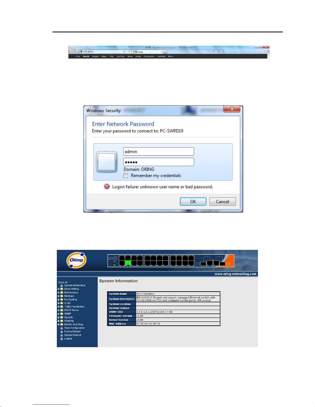
System Login
1. Launch the Internet Explorer.
2. Type http:// and the IP address (default is 192.168.10.1) of the switch. Press
“Enter”.
RES-P3242GCL SERIES User’s Manual
7
3. The login screen appears.
4. Key in the username and password. The default username and password is
“admin”.
5. Click “Enter” or ”OK” button, then the main interface of the Web-based
management appears.
Login screen
Main Interface
Main interface
RES-P3242GCL SERIES User’s Manual
8
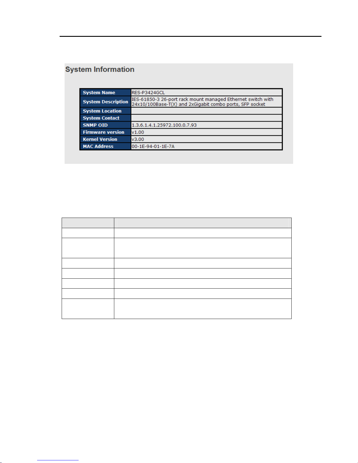
4.1.2 System Information
System Information interface
System Information will display the configuration of Basic Setting / Switch Setting page.
The following table describes the labels in this screen.
Label Description
System Name
Display the system name of switch.
System
Description
Display the description of switch.
System Location
Display the location of switch.
System Contact
Display the name of contact person or organization
Firmware Version
Display the switch’s firmware version
Kernel Version
Display the kernel software version
MAC Address
Display the unique hardware address assigned by manufacturer
(default)
RES-P3242GCL SERIES User’s Manual
9
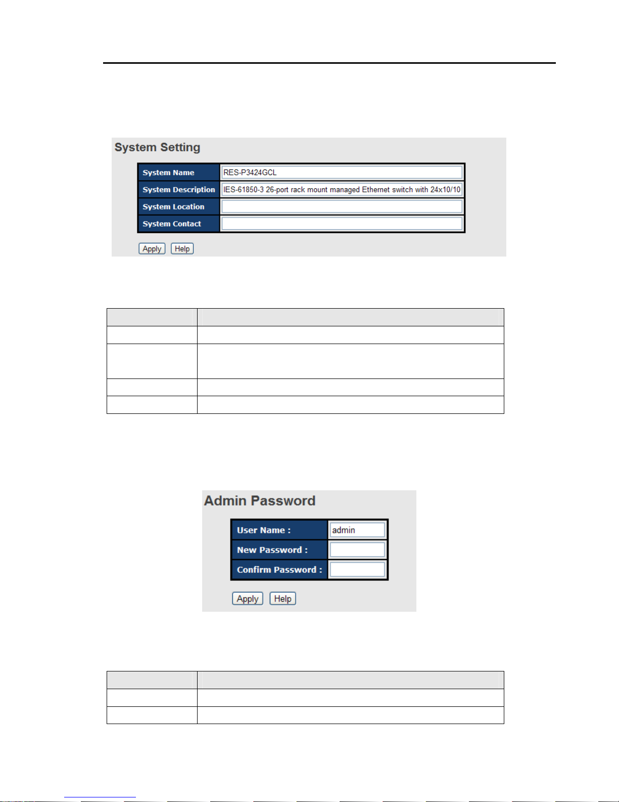
4.1.3 Basic setting
4.1.3.1 Switch Setting
Switch setting interface
The following table describes the labels in this screen.
Label Description
System Name
Assign the name of switch. The maximum length is 64 bytes
System
Description
Display the description of switch.
System Location
Assign the switch physical location. The maximum length is 64 bytes
System Contact
Enter the name of contact person or organization
4.1.3.2 Admin Password
Change web management login username and password for the management security
issue
Admin Password interface
The following table describes the labels in this screen.
Label Description
User name
Key in the new username(The default is “admin”)
New Password
Key in the new password(The default is “admin”)
RES-P3242GCL SERIES User’s Manual
10
Confirm
password
Re-type the new password.
Apply
Click “Apply” to set the configurations.
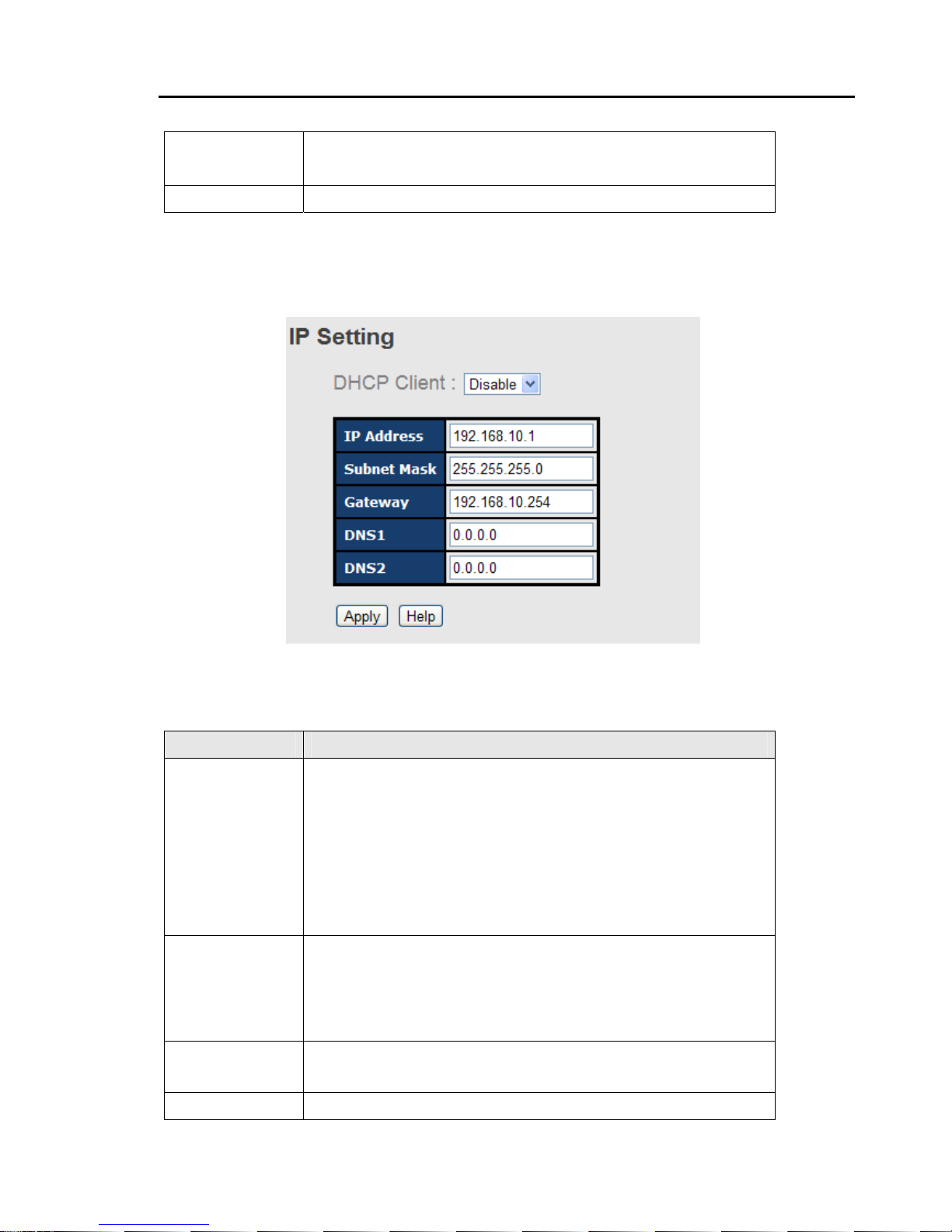
4.1.3.3 IP Setting
You can configure the IP Settings and DHCP client function throug h IP configuration.
IP Configuration interface
The following table describes the labels in this screen.
Label Description
DHCP Client
To enable or disable the DHCP client function. When DHCP client
function is enabling, the switch will be assigned the IP address from
the network DHCP server. The default IP address will be replaced by
the IP address which the DHCP server has assigned. After clicking
“Apply” button, a popup dialog shows up to inform when the DHCP
client is enabling. The current IP will lose and you should find a new
IP on the DHCP server.
IP Address
Assign the IP address that the network is using. If DHCP client
function is enabling, you do not need to assign the IP address. The
network DHCP server will assign the IP address for the switch and it
will be display in this column. The default IP is 192.168.10.1
Subnet Mask
Assign the subnet mask of the IP address. If DHCP client function is
enabling, you do not need to assign the subnet mask
Gateway
Assign the network gateway for the switch. The default gateway is
RES-P3242GCL SERIES User’s Manual
11
192.168.10.254
DNS1
Assign the primary DNS IP address
DNS2
Assign the secondary DNS IP address
Apply
Click “Apply” to set the configurations.
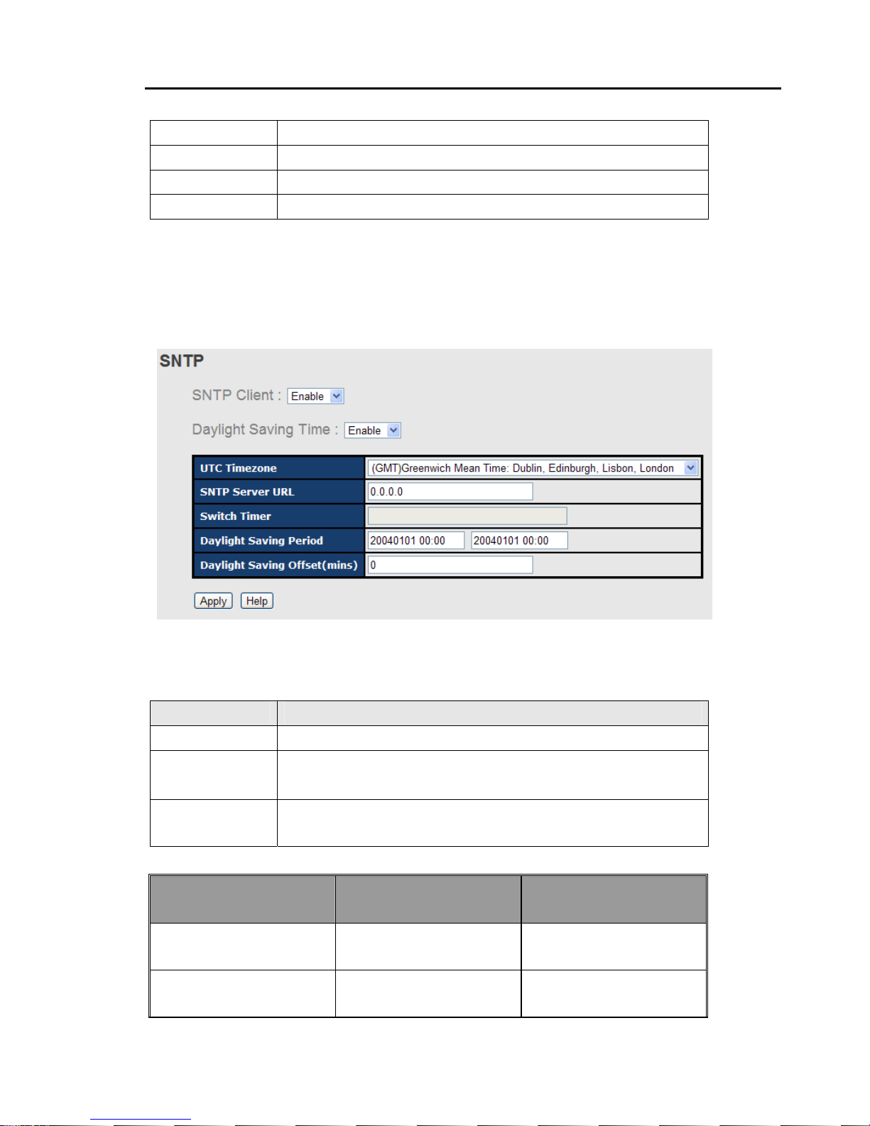
4.1.3.4 SNTP (Time)
The SNTP (Simple Network Time Protocol) settings allow you to synchronize switch clocks
in the Internet.
SNTP Configuration interface
The following table describes the labels in this screen.
Label Description
SNTP Client
Enable or disable SNTP function to get the time from the SNTP server.
Daylight Saving
Time
Enable or disable daylight saving time function. When daylight saving
time is enabling, you need to configure the daylight saving time period.
UTC Time zone
Set the switch location time zone. The following table lists the
different location time zone for your reference.
Local Time Zone Conversion from UTC Time at 12:00 UTC
November Time Zone - 1 hour 1 1 am
Oscar Time Zone -2 hours 10 am

RES-P3242GCL SERIES User’s Manual
12
ADT - Atlantic Daylight -3 hours 9 am
AST - Atlantic Standard
EDT - Eastern Daylight
-4 hours 8 am
EST - Eastern Standard
CDT - Central Daylight
-5 hours 7 am
CST - Central Standard
MDT - Mountain Daylight
-6 hours 6 am
MST - Mountain Standard
PDT - Pacific Daylight
-7 hours 5 am
PST - Pacific Standard
ADT - Alaskan Daylight
-8 hours 4 am
ALA - Alaskan Standard -9 hours 3 am
HAW - Hawaiian Standard -10 hours 2 am
Nome, Alaska -1 1 hours 1 am
CET - Central European
FWT - French Winter
MET - Middle European
MEWT - Middle European
Winter
SWT - Swedish Winter
+1 hour 1 pm
EET - Eastern European,
USSR Zone 1
+2 hours 2 pm
BT - Baghdad, USSR Zone
2
+3 hours 3 pm
ZP4 - USSR Zone 3 +4 hours 4 pm
ZP5 - USSR Zone 4 +5 hours 5 pm
ZP6 - USSR Zone 5 +6 hours 6 pm
WAST - W est Australian
Standard
+7 hours 7 pm
CCT - China Coast, USSR
Zone 7
+8 hours 8 pm

RES-P3242GCL SERIES User’s Manual
13
JST - Japan Standard,
USSR Zone 8
+9 hours 9 pm
EAST - East Australian
Standa rd GST
Guam Standard, USSR
Zone 9
+10 hours 10 pm
IDLE - International Date
Line
NZST - New Zealand
Standard
NZT - New Zealand
+12 hours Midnight
Label Description
SNTP Sever IP
Address
Set the SNTP server IP address.
Daylight Saving
Period
Set up the Daylight Saving beginning time and Daylight Saving ending
time. Both will be different each year.
Daylight Saving
Offset
Set up the offset time.
Switch Timer
Display the switch current time.
Apply
Click “Apply” to set the configurations.
RES-P3242GCL SERIES User’s Manual
14
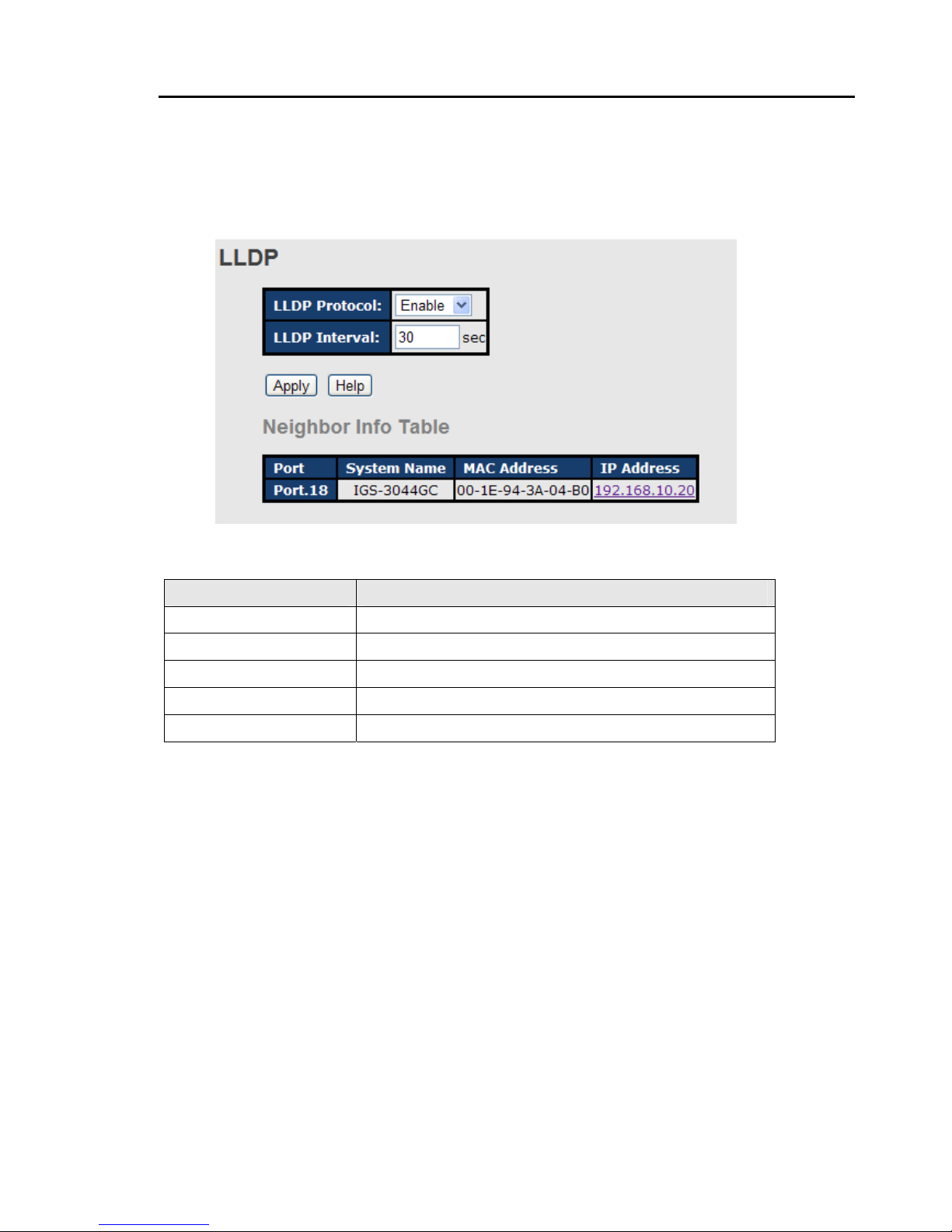
4.1.3.5 LLDP
LLDP (Link Layer Discovery Protocol) function allows the switch to advertise its information
to other nodes on the network and store the information it discovers.
The following table describes the labels in this screen.
Label Description
LLDP Protocol
“Enable” or “Disable” LLDP function.
LLDP Interval
The interval of resend LLDP (by default at 30 seconds)
Apply
Click “Apply” to set the configurations.
Help
Show help file.
Neighbor info table
Can show neighbor device info .
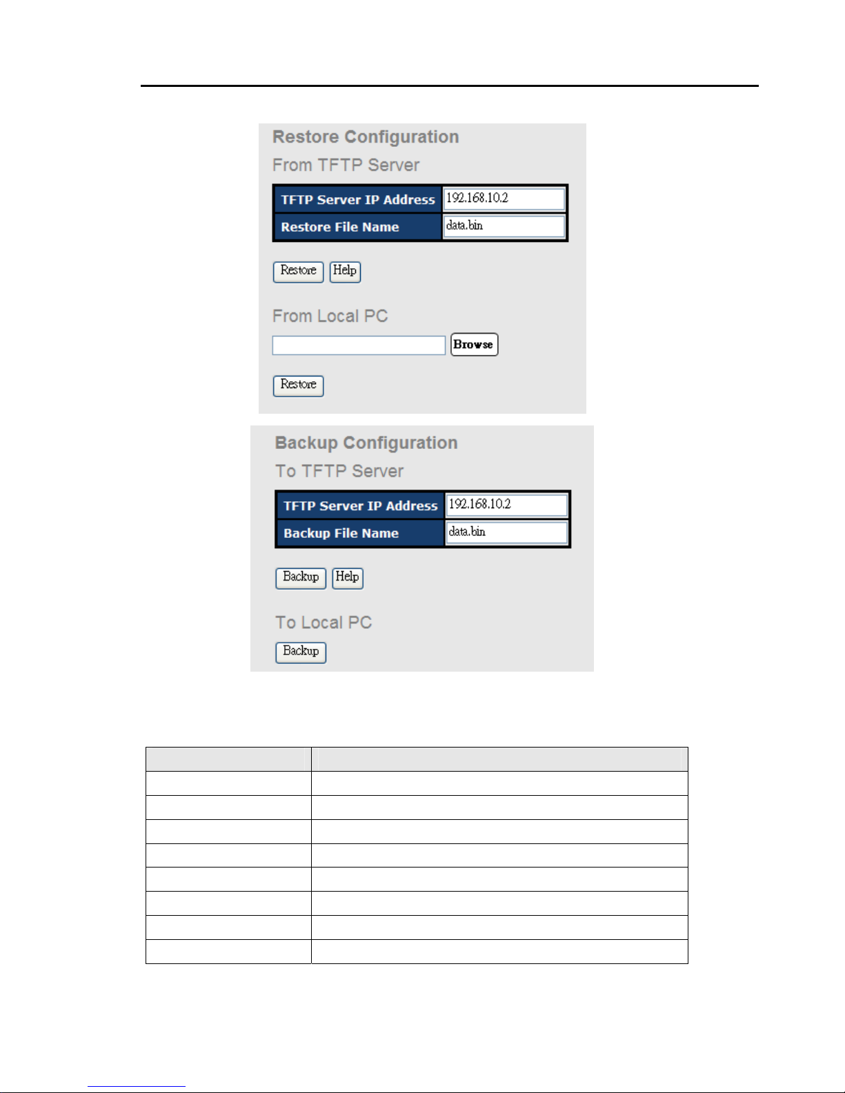
4.1.3.6 Backup & Restore
You can save current EEPROM value from the switch to TFTP server, then go to the TFTP
restore configuration page to restore the EEPROM value.
RES-P3242GCL SERIES User’s Manual
15
Backup & Restore interface
The following table describes the labels in this screen.
Label Description
TFTP Server IP Address
Fill in the TFTP server IP
Restore File Name
Fill the file name.
Restore
Click “restore” to restore the configurations.
Form Local PC
User can select file restore , not need TFTP server .
Restore File Name
Fill the file name.
Restore
Click “restore” to restore the configurations.
Backup
Click “backup” to backup the configurations.
To Local PC
User can download config file to switch . not need TFTP server
RES-P3242GCL SERIES User’s Manual
16
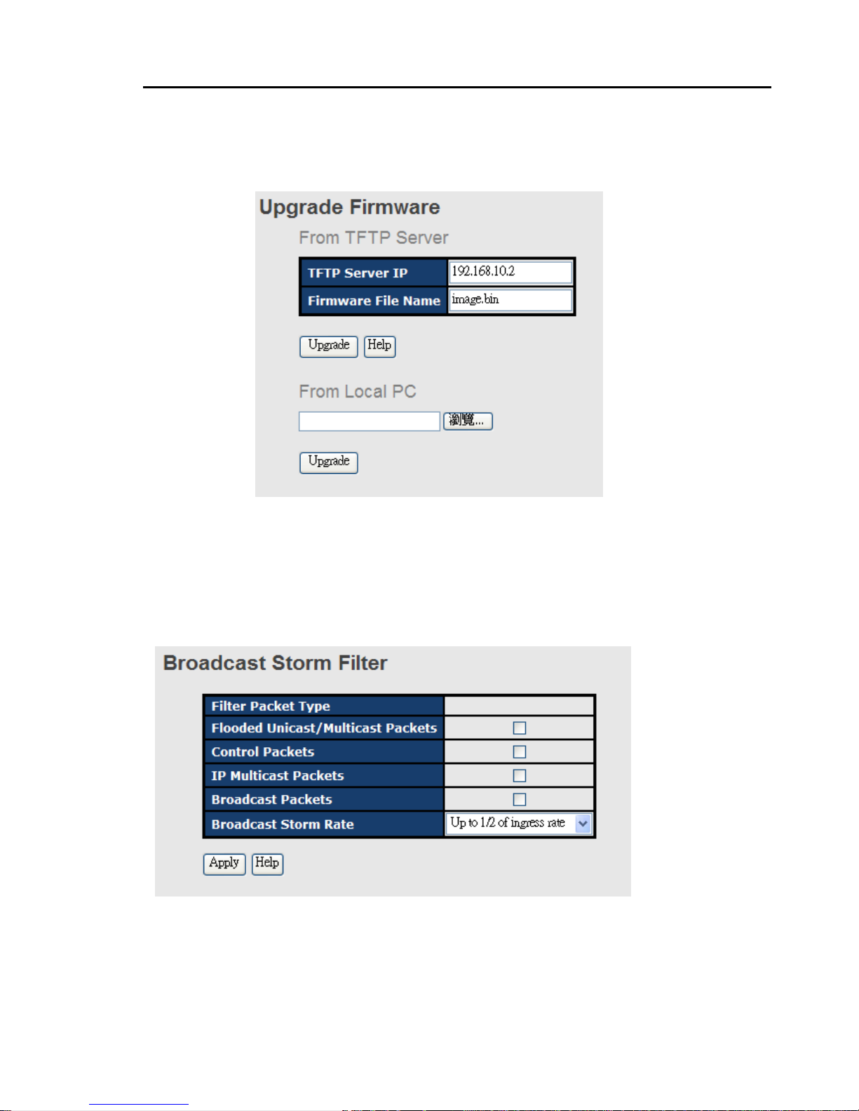
4.1.3.7 Upgrade Firmware
Upgrade Firmware allows you to update the switch firmware. Before updating, make sure
you have your TFTP server ready and the firmware image is on the TFTP server .
Update Firmware interface
4.1.3.8 Broadcast storm filter
Set the broadcast storm rate to prevent network crash..
1. Flooded Unicast / Multicast Packets: Enable/disable to limit the frame type.
2. Control Packets: Enable/disable to limit the frame type.
3. IP Multicast Packets: Enable/disable to limit the frame type.
4. Broadcast Packets: Enable/disable to limit the frame type.
5. Broadcast Storm Rate:
Set the filtering rate range from 1/2 to 1/16 of ingress.
RES-P3242GCL SERIES User’s Manual
17
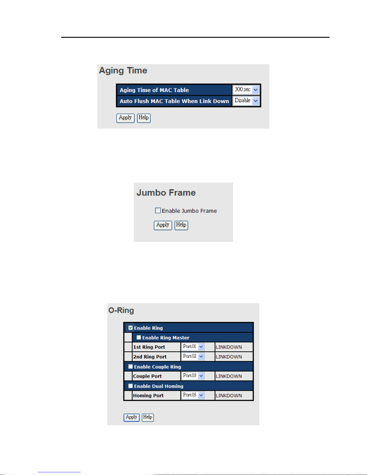
4.1.3.9 Aging Time
1. Aging Time of MAC Table: Default 300secs.
2. Auto Flush MAC Table When Link Down: enable/disable the function
4.1.3.10 Jumbo Frame
Enable/disable all ports Jumbo frame function.
4.1.4 Redundancy
4.1.4.1 O-Ring
O-Ring is the most powerful Ring in the world. The recovery time of O-Ring is less than 10
ms. It can reduce unexpected damage caused by network topology change. O-Ring
supports three Ring topologies: O-Ring, Coupling Ring and Dual Homing.
O-Ring interface

RES-P3242GCL SERIES User’s Manual
18
The following table describes the labels in this screen.
Label Description
Enable Ring
Mark to enable Ring.
Enable Ring Master
There should be one and only one Ring Master in a ring.
However if there are two or more switches which set Ring
Master to enable, the switch with the lowest MAC address will
be the actual Ring Master and others will be Backup Masters.
1st Ring Port
The primary port, when this switch is Ring Master.
2nd Ring Port
The backup port, when this switch is Ring Master.
Enable Coupling Ring
Mark to enable Coupling Ring. Coupling Ring can be used to
divide a big ring into two smaller rings to avoid effecting all
switches when network topology change. It is a good
application for connecting two Rings.
Coupling Port
Link to Coupling Port of the switch in another ring
. Coupling
Ring need four switch to build an active and a backup link.
Set a port as coupling port. The coupled four ports of four
switches will be run at active/backup mode.
Control Port
Link to Control Port of the switch in the same ring. Control
Port used to transmit control signals.
Enable Dual Homing
Mark to enable Dual Homing. By selecting Dual Homing
mode, O-Ring will be connected to normal switches through
two RSTP links (ex: backbone Switch). The two links work as
active/backup mode, and connect each O-Ring to the normal
switches in RSTP mode.
Apply
Click “Apply” to set the configurations.
Note: We don’t suggest you to set one switch as a Ring Master and a Coupling Ring at the same time due to heavy
load.
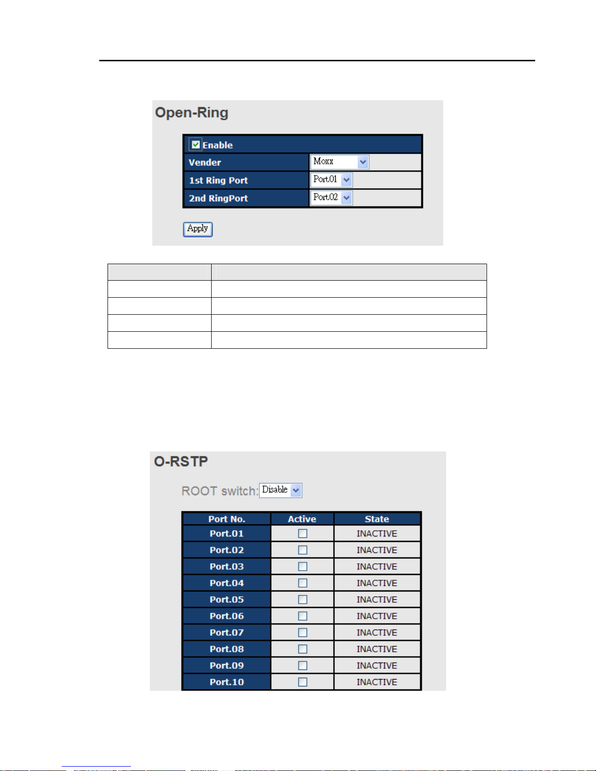
4.1.4.2 OPEN-Ring
Open-Ring technology can be applied for other vendor’s proprietary ring. Thus, you can
add switches of ORing into the network constructed by other ring technology and enable
Open-Ring to co-operate with other vendor’s managed switch.
RES-P3242GCL SERIES User’s Manual
19
Click ”Connect to other vendor’s ring…..” to join the ring constructed by other vendor.
Open-Ring interface
Label Description
Enable
Enabling the Open-Ring function
Vender
Choosing the venders that you want to join to their ring
1st Ring Port
Choosing the port which connect to the ring
2nd Ring Port
Choosing the port which connect to the ring
4.1.4.3 O-RSTP
O-RSTP is proprietary redundant ring technology invented by O-Ring. Different from
standard STP/RSTP, the recovery time of O-RSTP is less than 10mS and support more nodes
of connection in a ring topology.

RES-P3242GCL SERIES User’s Manual
20
O-RSTP interface
The application of O-RSTP is shown as below.
O-RSTP connection
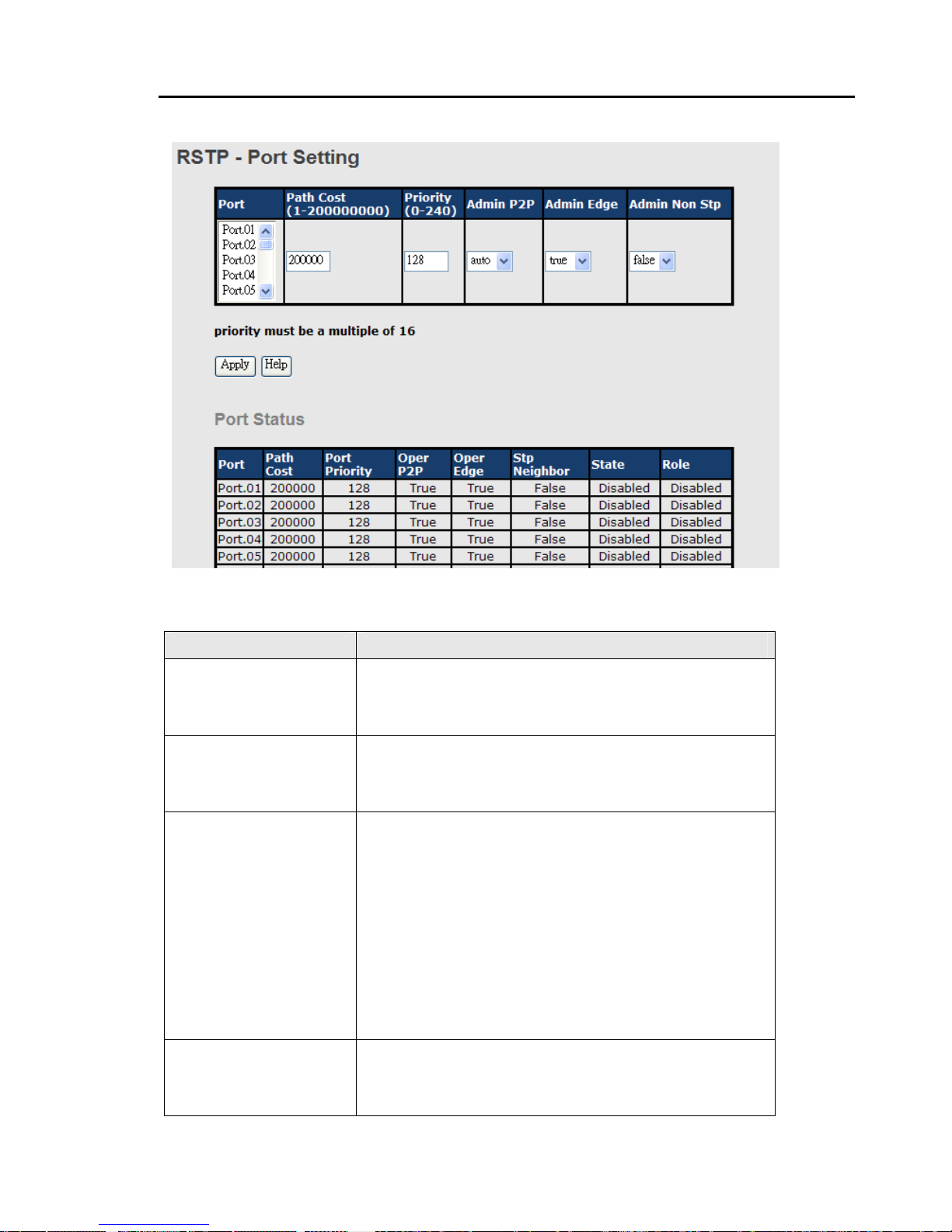
4.1.4.4 RSTP
The Rapid Sp anning Tree Protocol (RSTP) is an evolution of the Spanning Tree Protocol. It
provides faster spanning tree convergence after a topology change. The system also
supports STP and the system will auto detect the connecte d device that is running STP or
RSTP protocol.
RSTP setting
You can enable/disable RSTP function, and set parameters for each port.
RSTP Setting interface

RES-P3242GCL SERIES User’s Manual
21
The following table describes the labels in this screen.
Label Description
RSTP mode
You must enable or disable RSTP function before configuring
the related parameters.
Priority (0-61440)
A value used to identify the root bridge. The bridge with the
lowest value has the highest priority and is selected as the
root. If the value changes, You must reboot the switch. The
value must be multiple of 4096 according to the protocol
standard rule.
Max Age Time(6-40)
The number of seconds a bridge waits without receiv ing
Spanning-tree Protocol configuration messages before
attempting a reconfiguration. Enter a value between 6
through 40.
Hello Time (1-10)
The time that controls switch sends out the BPDU packet to
check RSTP current status. Enter a value between 1 through
10.
Forwarding Delay Time
(4-30)
The number of seconds a port waits before changing from its
Rapid Spanning-Tree Protocol learning and listening states to
the forwarding state. Enter a value between 4 through 30.
Apply
Click “Apply” to set the configurations.
NOTE: Follow the rule to configure the MAX Age, Hello Time, and Forward Delay Time.
2 x (Forward Delay Time value –1) > = Max Age value >= 2 x (Hello Time value +1)
Show RSTP algorithm result at this table
RES-P3242GCL SERIES User’s Manual
22
Label Description
Path Cost (1-200000000)
The cost of the path to the other bridge from this transmitting
bridge at the specified port. Enter a number 1 through
200000000.
Port Priority (0-240)
Decide which port should be blocked by priority in LAN.
Enter a number 0 through 240. The value of priority must be
the multiple of 16
Admin P2P
Some of the rapid state transactions that are possible within
RSTP are dependent upon whether the port concerned can
only be connected to exactly one other bridge (i.e. It is served
by a point-to-point LAN segment), or it can be connected to
two or more bridges (i.e. It is served by a shared medium LAN
segment). This function allows the P2P status of the link to
be manipulated administratively. True means P2P enabling.
False means P2P disabling.
Admin Edge
The port directly connected to end stations, and it cannot
create bridging loop in the network. To configure the port as
an edge port, set the port to “True”.
RES-P3242GCL SERIES User’s Manual
23
Admin Non STP
The port includes the STP mathematic calculation. True is
not including STP mathematic calculation. False is including
the STP mathematic calculation.
Apply
Click “Apply” to set the configurations.
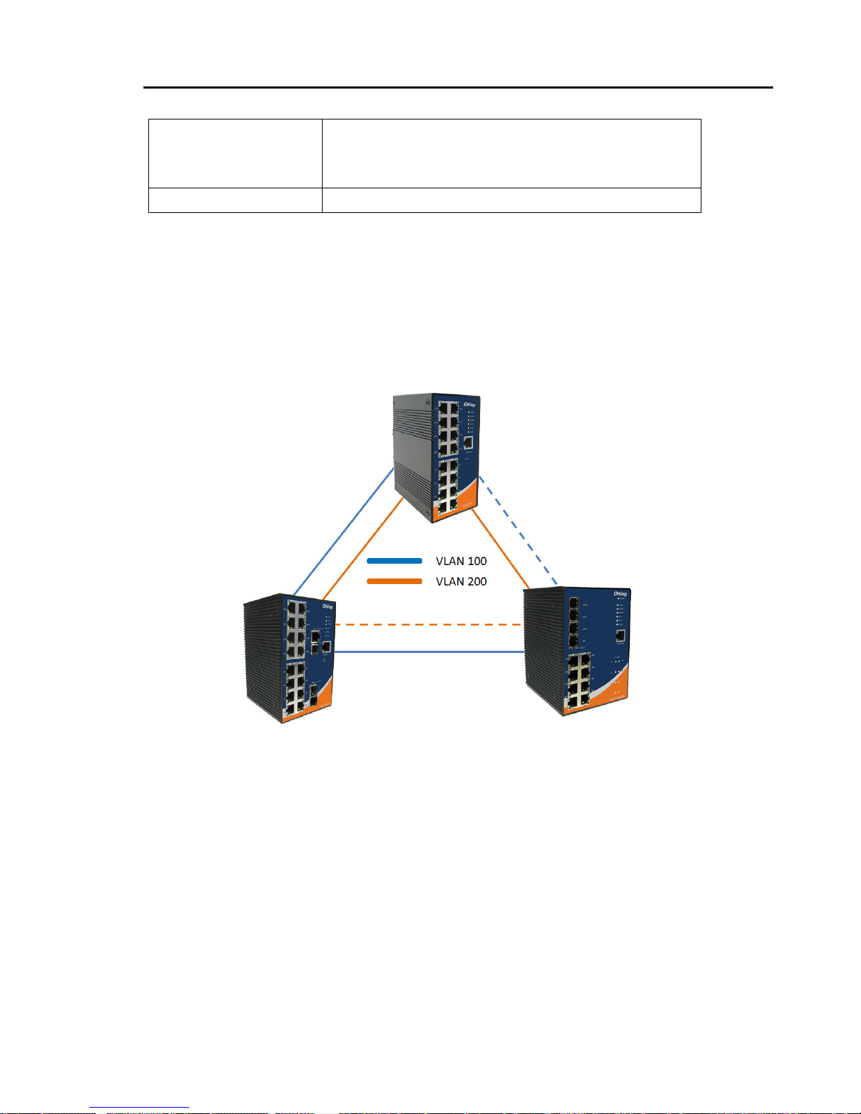
4.1.4.5 MSTP
Multiple Spanning Tree Protocol (MSTP) is a standard protocol base on IEEE 802.1s. The
function is that several VLANs can be mapping to a reduced number of spanning tree
instances because most networks do not need more than a few logical topol ogies. It supports
load balancing scheme and the CPU is sparer than PVST (Cisco proprietary technology).
 Loading...