

Page 1
RES-1242P
100M
Quick InstallationGuide
Version 1.0
Quick Installation Guide
Introduction
PRINTED ON RECYCLED PAPER
QIG
1907-2-29-RES1242P-1.0
The is an unmanaged Ethernet switch with twenty-four
10/100Base-T(X) LANports and two100Base-FX SFP ports. The SFPports
can meetdemand for long-distancedata transmission. With a wide
operating temperature range from -40C to 70 C, the device can work
reliably in harsh environments.
RES-1242P
oo
Preparation
Before youbegin installing theswitch, make sureyou have allof the package
contents available.
Elevated OperatingAmbient:
ReducedAir Flow:
Mechanical Loading:
If installed in a closed or multi-unit rack
assembly,the operating ambienttemperature of therack environment maybe
greater thanroom ambient. Therefore,consideration should begiven to
installing theequipment in anenvironment compatible withthe maximum
ambient temperature(Tma) specified bythe manufacturer.
Installation of the equipment in a rack should be such
that the amount of air flow required for safe operation of the equipment is
not compromised.
Mounting of the equipment in the rack should be
such that a hazardous condition is not achieved due to uneven mechanical
loading
.
Circuit Overloading:Consideration should begiven to theconnection of the
equipment tothe supply circuitand the effectthat overloading ofthe circuits
might haveon overcurrent protectionand supply wiring.Appropriate
consideration ofequipment nameplate ratingsshould be used when addressing
this concern.
Safety & Warnings
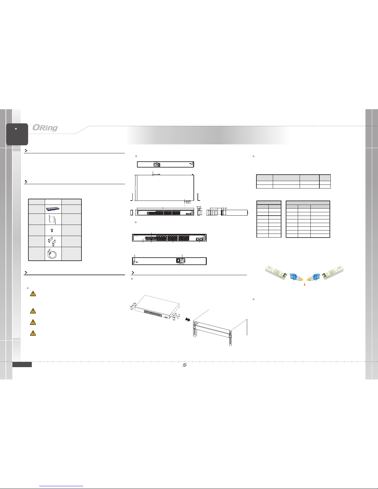
Dimension
Panel Layouts
1. PowerLED
2. LNK/ACTindicator for LANports
3. Speedindicator for LANports
4. LANports
5. SFPports
Front View
Rear View
Network Connection
Package Contents
Contents
QIG
Screw (M3X4)
Powercord
Rack-mounted
kit(L&R)
Number
X1
X8
X1
X1
RES-1242P
Pictures
X1
1 2
1. Groundscrew
2. ACpower input (100V~240V
/ 50~60Hz)
The devicehas standard Ethernetports. Accordingto the linktype, the switchuses CAT3, 4,
5,5e UTPcables to connectto any othernetwork devices (PCs,servers, switches, routers,or
hubs). Pleaserefer to thefollowing table forcable specifications.
Cable Typesand Specifications:
Cable Type Max. Length Conne ctor
10BASE-T Cat. 3, 4,5 100-ohm UTP 100m (328 ft) RJ-45
100BASE-TX Cat. 5100-ohmUTP UTP100m (328ft) RJ-45
For pinassignments for differenttypes of cables,please refer tothe following
tables.
The device is shipped with the followingitems. If anyof these itemsis
missing ordamaged, please contactyour customer servicerepresentative
for assistance.
Installation
Rack-mounting
Step 1: .
Step 2:
Attach thewall-mounting kits to the left and right sides of the device on thefront
With frontbrackets orientated infront of therack, fasten thebrackets to therack using twomore
screws.
RES-1242P
RES-1242P
31
2
5
4
Note: and signsrepresent the polarityof the wiresthat make upeach wire pair.“+” “-”
10/100Base-T(X) MDI/ MDI-X Pin Assignm ents:
PinNumber MDIp ort MDI-Xport
1 TD+(transmit) RD+(receive)
2 TD-(transmit) RD-( receive)
3 RD+(receive) TD+(tra nsmit)
4 Not used Not used
5 Not used Not used
6 RD-(receive) TD-(transmit)
7 Not used Not used
8 Not used Not used
RES-1242P
100M
10/100 Base-T(X) RJ-45
PinNumber Assi gnment
1TD+
2TD-
3 RD+
4 Not used
5 Not used
6RD-
7 Not used
8 Not used
SFP Connection
The devicesupports fiber connection via SFP transceivers which are hot-swappable and
can be plugged into the SFP ports to connect the switch with the fiber-optic network.
Please remember that the TX port of SwitchA should be connected to theRX port of
Switch B.
Fiber cord
Switch A
Switch B
Wiring
The deviceis powered byAC electricity.Simply insert theAC power cableto the powerconnector
at theback of theswitch and turnon the powerswitch. The inputvoltage isAC 100V~240V /
50~60Hz.
AC PowerConnection
Grounding andwire routing helplimit the effectsof noise dueto electromagnetic interference
(EMI). Runthe ground connectionfrom the groundscrews to thegrounding surface priorto
connecting devices.
Grounding
SWITCH
Rack-Mount
Rack-Mount Ethernet Switch
Page 2
QIG
Quick InstallationGuide
PRINTED ON RECYCLED PAPER
Version 1.0
Quick Installation Guide
Configurations
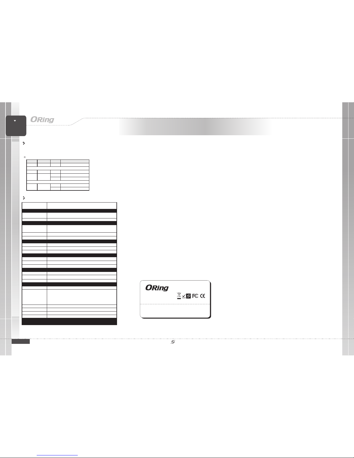
After installingthe switch andconnecting cables, thegreen power LEDshould turn on.
Please referto the followingtable for LEDdefinition.
LED indication table
Regulatory Approvals
FCCPart 15, CISPR(EN55022) class BEMI
EN61000-4-2(ESD)
EN61000-4-3(RS)
EN61000-4-4(EFT)
EN61000-4-5(Surge)
EN61000-4-6(CS)
EN61000-4-8
EN61000-4-11
EMS
Warranty
5years
Warranty
5years
ORing IndustrialNetworking Corp.
Copyright© 2015 ORing
All rightsreserved.
TEL: +886-2-2218-1066
FAX:+886-2-2218-1014
Website: www.oring-networking.com
E-mail: [email protected]
IEC60068-2-27Shock
IEC60068-2-32FreeFall
Specifications
ORing SwitchModel
Physical Ports
Technology
EthernetStandards
10/100Base-T(X)with P.S.E.
Portsin RJ45 AutoMDI/MDIX
RES-1242P
24
IEEE802.3 for 10Base-T
IEEE802.3u for 100Base-TXand 100Base-FX
IEEE802.3x for Flowcontrol
MACTable
4096
Processing
Store-and-Forward
100Base-FXSFP Port
2
Power
Powerconsumption(Typ.)
25Watts Max.
Overloadcurrent protection
Present
Powerinput
100~240VACwith power socket
Environmental
-40to85C(-40to185F)
oo
StorageTemperature
OperatingTemperature
Physical Characteristic
Dimension(WxDxH)
Weight (g)
2450g
5%to 95% Non-condensing
OperatingHumidity
Enclosure
IP-30
440(W)x200(D)x44(H)mm(17.32x7.87x1.73inches)
-40to75C(-40to167F)
oo
LED Color Status Descri ption
PWR Green On System p ower on
10/100Base-T(X) RJ45 p ort
Link/Act Green On Port is co nnected
On Port is running at 100Mbps
Speed Green
Off Port i s running i s 10Mbps
100Base-FX SF P port
On Port connect ed
Link/Act Green
Blinking Transmitti ng data
IEC60068-2-6Vibration
EN60950-1Safety
MTBF(Hours)
510613
RES-1242P
RES-1242P
SWITCH
Rack-Mount
Rack-Mount Ethernet Switch
 Loading...