

ORiNG PET-102GT Plus Quick Installation Manual
PET-102GT++
Quick InstallationGuide
Version 1.0
Quick Installation Guide
PRINTED ON RECYCLED PAPER
QIG
1907-2-29-PET102GT++-1.0
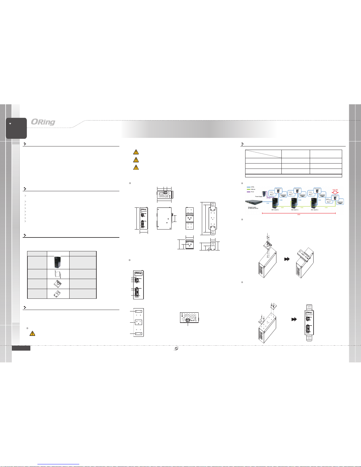
Installation and Distance
DIN-rail
Step 1:
Step 2:
Slant the device and screwthe Din-railkit onto theback of thedevice, right in the
middle of the back panel.
Slide thedevice onto aDIN-rail from theDin-rail kit andmake sure thedevice clicks into
the rail firmly.
Dimension
Panel Layouts
Front Panel
1. PowerLED
2. LNK/ACTindicator for P.D.port
3. P.D.port
4. PoEstatus LED forP.D port
5. LNK/ACTindicator for P.S.E.port
6. P.S.E.LED
7. PoEstatus LED forP.S.E port
1. Din-railscrew holes
2. Wall-mountscrew holes
PET-102GT++
PET-102GT++
Introduction
The is a high power PoE extender and compatible with
IEEE802.3at/af standard. With one 10/100/1000TxBase-T(X) P.D. input port
and two10/100/1000TxBase-T(X) P.S.E.output ports, thedevice can notonly
deliver Ethernet databut also forward power from the previous PoE device
to the next device. Furthermore, the can be powered by
external DC power sources. By using external DC power tocompensate for
power losses caused by long-haul transmission, users can continue to use
the PoE extender to enlarge the distance unlimitedly. With the ability to
provide 90Watts PoE power per port, the is surely a userfriendly andhigh-power PoE extender.
PET-102GT++
PET-102GT++
PET-102GT++
Package Contents
The device is shipped with the following items. If any of these items is
missing or damaged, please contact your customer service representative
for assistance.
Contents
PET-102GT++
Pictures Number
X1
QIG
X1
Preparation
Before installation, make sure you have all of the package contents
available and a PC with Microsoft Internet Explorer 6.0 or later, for using
web-based system management tools.
Elevated OperatingAmbient: Ifinstalled in aclosed environment, make sure
the operating ambient temperature is compatible with the maximum
ambient temperature (Tma) specified by the manufacturer.
Safety & Warnings
DIN-railkit
X1
Wall-MountKit
X2
Rear Panel
1
TopPanel
1
1. Terminalblock
Wall-mount
Extender
HIGH POWER POE++
INDUSTRIAL
Industrial High Power Extender
7
1
2
6
25.0
5.0
24.0
40.0
40.0
25.5
50.0
34.7 17.3 23.0
33.6
173.0
145.0
115.0
PET-102GT++
3
4
5
2
2
Step 1:
Step 2:
Step 3:
Screw thetwo pieces ofwall-mount kits to the topand bottom panels of the device. A
total of screws are required, as shown below.
Use thedevice, with wall mount plates attached, asa guide tomark the correctlocations
of thefour screws.
Insert ascrew head through middle of thekeyhole-shaped aperture on the plate, and
then slide the device downwards. Tightenthe screwhead for added stability.
eight
ReducedAir Flow:
Mechanical Loading:
Circuit Overloading:
Make surethe amount ofair flow requiredfor safe operationof the
equipment isnot compromised during installation.
Make surethe mounting ofthe equipment is not in a hazardous
condition dueto uneven mechanicalloading.
Consideration shouldbe given tothe connection ofthe equipment to
the supplycircuit and theeffect that overloadingof the circuitsmight have onovercurrent
protection andsupply wiring.Appropriate consideration ofequipment nameplate ratings
should beused when addressingthis concern.
Features
Support 1port PoE P.D. inputto 2 portPOE P.S.Eoutput with 10/100/1000Base-T(X)
for powerand data extender
Supports P.S.E. based onIEEE 802.3af/at standard
PoE P.D. inputsupport 90watts max.
PoE P.S.E. outputsupport 90watts max.per port
Support auto-negotiationand auto-MDI/MDI-X
Multiple unit, daisy-chain installationsupport
High reliabilityand rigid IP-30housing
DIN-Rail andwall mounting enabled
Powerinput on thefirst unit
P.D. attachedon the lastunit
50VDC 57VDC
IEEE802. 3at (25 .5W) Extended 2 uni t
Max. Distanceup to 300 meters
Extended 3 uni ts
Max. Distanceup to 400 meters
IEEE802.3af (12.95W) Extend ed 4 units
Max. Distanceup to 500 meters
Extended 5 uni ts
Max dis tance up t o 600 me ters
NO P.D.on the lastunit Extended 5 uni ts
Max. Distanceup to 600 meters
Extended 6 uni ts
Max. Distanceup to 700 meters
Note : The t est resu lt is wi th one P. D. device con nected to the l ast unit an d only fo r referenc e.
Example for57VDC power inputand attachedIEEE802.3at P.D.
PET-102GT++
ICP Deutschland GmbH | +49(0)7121-14323-20 | sales@icp-deutschland.de | www.icp-deutschland.de
QIG
Quick InstallationGuide
PRINTED ON RECYCLED PAPER
Quick Installation Guide
ORing IndustrialNetworking Corp.
Copyright© 2017 ORing
All rightsreserved.
TEL: +886-2-2218-1066
FAX:+886-2-2218-1014
Website: www.oring-networking.com
E-mail: support@oring-networking.com
QIG
Version 1.0
10/100 Base-T(X)
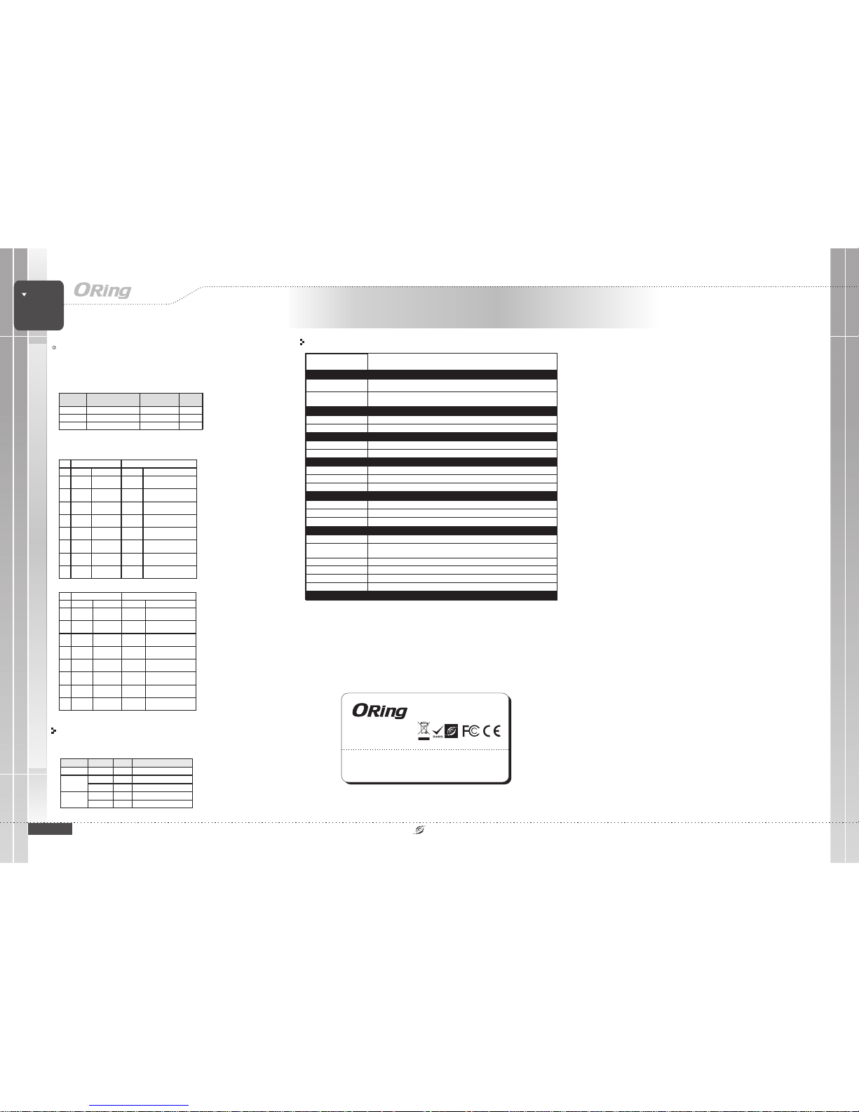
Specifications
ORing InjectorModel
RJ-45EthernetPortwithP.D.
Input
1
Physical Ports
PET-102GT++
RJ-45EthernetPortwithP.S.E.
Output
Operating Voltage
Input Voltage
50~57VDC
Output Power
90Watts max perport(*Note)
Short Circuitprotection
Present
OverLoad protection
Present
Physical Characteristic
Enclosure
IP-30
Dimension(WxDxH)
41(W)x75(D)x115(H)mm(1.61x2.95x4.52inch)
Weight (g)
Environmental
-40to80C(-40to176F)
oo
StorageTemperature
5%to 95% Non-condensing
OperatingHumidity
Regulatory Approvals
FCCPart 15, CISPR(EN55022) class A
EMI
EN61000-4-2(ESD), EN61000-4-3 (RS),EN61000-4-4 (EFT), EN61000-4-5 (Surge),
EN61000-4-6(CS), EN61000-4-8, EN61000-4-11
EMS
IEC60068-2-27
Shock
IEC60068-2-31
IEC60068-2-6
Vibration
Free Fall
Warranty
5years
EN60950-1
Safety
-20to70C(-4to158F)
oo
OperatingTemperature
349g
For pinassignments for differenttypes of cables,please refer to the following tables.
PET-102GT++
PET-102GT++
Extender
HIGH POWER POE++
INDUSTRIAL
Industrial High Power Extender
RJ-45Input (DataOnly) RJ-45 Output(Data and Power)
Pin Symbol
Description
Symbol
Description
1Rx+DataReceive
Rx+
(Vdc1+)
Data Receiv e and
Feedingpower(+)
2Rx-DataReceive
Rx-
(Vdc1+)
Data Receiv e and
Feeding power(+)
3Tx+DataTransmit
Tx+
(Vdc1-)
Data Tran smit and
Feedingp ower(-)
4NCNotConnected
NC
(Vdc2+)
Not Connected
Feeding power(+)*
5NCNotConnected
NC
(Vdc2+)
Not Connected
Feeding power(+)*
6Tx-DataTransmit
Tx-
(Vdc1-)
Data Tran smit and
Feedingp ower(-)
7NCNotConnected
NC
(Vdc2-)
Not Connected
Feedingp ower(-)*
8NCNotConnected
NC
(Vdc2-)
Not Connected
Feedingp ower(-)*
RJ-45 In put (Dat a Onl y) RJ-45 Output (Dat a and P ower)
Pin Symbol Descrip tion Symbol Description
1 BI_DA+ Data BI _DA+
BI_DA+
(Vdc1+)
Data BI_DA+ and
FeedingPower(+)
2 BI_DA- DataBI_DA-
BI_DA-
(Vdc1+)
Data BI_DA- and
FeedingPower(+)
3 BI_DB+ Data BI _DB+
BI_DB+
(Vdc1-)
DataBI_DB+and Feeding
Power(-)
4BI_DC+DataBI_DC+
BI_DC+
(Vdc2+)
DataBI_DC+
FeedingPower(+)*
5 BI_DC- Dat a BI_DC-
BI_DC-
(Vdc2+)
Data BI_D C-
FeedingPower(+)*
6 BI_DB- DataBI_DB-
BI_DB-
(Vdc1-)
Data BI_DB- and
FeedingPower(-)
7BI_DD+DataBI_DD+
BI_DD+
(Vdc2-)
Data BI_DD +
Feeding Power(-)*
8 BI_DD- Da ta BI_DD-
BI_DD-
(Vdc2-)
Data BI_DD-
Feeding Power(-)*
1000 Base-T
*:Only valid forPoE++ connection
Configurations
After installingthe device and connecting cables, the green powerLED
should turnon. Please refer to the following tablet for LED indication.
LED
Color
Status
Description
Power Green On DCpowermoduleactivated
PoE Input
Green On Powerisreceived
Amber On PoE inputmoduleactivated
PoE Outpu t
Green On P oweris transmitted
Amber On PoE output moduleactivated
2
Protection
Cable Typesand Specifications:
Cable
Type
Max.Length
Connector
10BASE-T Cat. 3,4 ,5 100-ohm UTP 100m (328 ft) RJ-45
100BASE-T X Cat. 5100 -ohmUTP UTP 100m (328 ft) RJ-45
1000BASE -T Cat. 5/Cat. 5e100- ohmUTP UTP 100m (328ft) RJ-45
*Note :LTPoE++ PSE technologyis applied onthis product. Onlywhen an LTPoE++ Powered Device (PD)
isattachedcanthePSEportdeliverupto90Wofoutputpower.
TM TM
Network Connection
The device has three standard Ethernet ports. According to the link type, the device
uses CAT 3,4,5,5e UTP cables to connect to any other network devices (PCs, servers,
switches, routers, or hubs). Please refer to the following table for cable specifications.
ICP Deutschland GmbH | +49(0)7121-14323-20 | sales@icp-deutschland.de | www.icp-deutschland.de
 Loading...